US4655665A - Bobbin magazine for a travelling service device of a yarn processing machine - Google Patents
Bobbin magazine for a travelling service device of a yarn processing machine Download PDFInfo
- Publication number
- US4655665A US4655665A US06/698,628 US69862885A US4655665A US 4655665 A US4655665 A US 4655665A US 69862885 A US69862885 A US 69862885A US 4655665 A US4655665 A US 4655665A
- Authority
- US
- United States
- Prior art keywords
- stick
- magazine
- arrangement
- bobbin
- tubes
- Prior art date
- Legal status (The legal status is an assumption and is not a legal conclusion. Google has not performed a legal analysis and makes no representation as to the accuracy of the status listed.)
- Expired - Fee Related
Links
Images


Classifications
-
- B—PERFORMING OPERATIONS; TRANSPORTING
- B65—CONVEYING; PACKING; STORING; HANDLING THIN OR FILAMENTARY MATERIAL
- B65H—HANDLING THIN OR FILAMENTARY MATERIAL, e.g. SHEETS, WEBS, CABLES
- B65H49/00—Unwinding or paying-out filamentary material; Supporting, storing or transporting packages from which filamentary material is to be withdrawn or paid-out
- B65H49/38—Skips, cages, racks, or containers, adapted solely for the transport or storage of bobbins, cops, or the like
-
- B—PERFORMING OPERATIONS; TRANSPORTING
- B65—CONVEYING; PACKING; STORING; HANDLING THIN OR FILAMENTARY MATERIAL
- B65H—HANDLING THIN OR FILAMENTARY MATERIAL, e.g. SHEETS, WEBS, CABLES
- B65H67/00—Replacing or removing cores, receptacles, or completed packages at paying-out, winding, or depositing stations
- B65H67/06—Supplying cores, receptacles, or packages to, or transporting from, winding or depositing stations
- B65H67/067—Removing full or empty bobbins from a container or a stack
-
- B—PERFORMING OPERATIONS; TRANSPORTING
- B65—CONVEYING; PACKING; STORING; HANDLING THIN OR FILAMENTARY MATERIAL
- B65H—HANDLING THIN OR FILAMENTARY MATERIAL, e.g. SHEETS, WEBS, CABLES
- B65H67/00—Replacing or removing cores, receptacles, or completed packages at paying-out, winding, or depositing stations
- B65H67/06—Supplying cores, receptacles, or packages to, or transporting from, winding or depositing stations
- B65H67/068—Supplying or transporting empty cores
-
- B—PERFORMING OPERATIONS; TRANSPORTING
- B65—CONVEYING; PACKING; STORING; HANDLING THIN OR FILAMENTARY MATERIAL
- B65H—HANDLING THIN OR FILAMENTARY MATERIAL, e.g. SHEETS, WEBS, CABLES
- B65H2701/00—Handled material; Storage means
- B65H2701/30—Handled filamentary material
- B65H2701/31—Textiles threads or artificial strands of filaments
Definitions
- the present invention relates to bobbin magazines for use with a travelling service device for servicing operating stations of a yarn processing machine.
- the invention is intended particularly, but not exclusively, for use in connection with travelling doffers for open-end spinning machines, for example rotor spinning machines.
- a suitable package transporting means for example a conveyor belt extending longitudinally of the central portion of the machine
- a fresh bobbin tube into the package holder of the spinning station so that yarn newly spun at that spinning station can be wound up on the fresh bobbin tube
- the present invention relates to systems in which the travelling doffing device carries its own bobbin magazine so that during its patrolling movements the doffing device carries a stock of bobbin tubes, the maximum size of which is limited only by the capacity of the magazine.
- bobbin magazine for a rotor spinning machine which produces cylindrical packages or "cheeses". These are produced on cylindrical bobbin tubes which can be made to roll in a substantially predetermined fashion in and from the magazine. Furthermore, such bobbin tubes can be made substantially symmetrical about their middle section so that there is no left-hand/right-hand problem during the transfer of a bobbin tube to a spinning station. Accordingly, there is generally no need to provide complicated feed equipment in association with magazines for cylindrical bobbins, and the available space on the doffer can be used efficiently for bobbin storage.
- the doffer may also be designed for multipurpose operation, and in particular for automatic start-up of the machine. In such circumstances all of the package holders in the spinning machine may be empty at the beginning of the start-up operation and the doffer may be required to insert a bobbin tube into the package holder of each spinning station in succession as a part of its start-up sequence at that station.
- 4,066,218 proposes a system in which a bobbin magazine on the doffer consists of a single stick of telescoped tubes, and an automatic loading device provided at one end of the machine comprises an elevator adapted to receive a plurality of sticks of tubes and to transfer them one by one to the doffer magazine as and when called for.
- the axes of the bobbin tubes are aligned along the length of the machine in both the doffer magazine and the loading station elevator.
- German Published Patent Application No. 2,131,957 describes a doffer magazine in which a plurality of sticks of telescoped bobbin tubes can be mounted in respective compartments of a carousel-like device rotatable about an axis parallel to the axes of the bobbin tubes in the sticks. The device can be rotated to bring the sticks successively into alignment with a separating station at which individual tubes can be separated from the stick currently aligned with the separating station.
- the mounting of this magazine in the doffer is not shown, but the sticks of tubes are disposed vertically in the magazine, and accordingly the individual tubes would normally have to be re-oriented after leaving the magazine before insertion in a spinning station in which the bobbin axes are normally disposed horizontally. Accordingly, neither of the above publications shows a simple system providing for an efficient use of the available storage space.
- Still another object of the present invention is so to construct the device of the type here under consideration as to have a sufficient capacity for accommodating conical bobbin tubes even for the start-up of the yarn processing machine.
- a concomitant object of the present invention is so to construct the device of the type here under consideration as to be relatively simple in construction, inexpensive to manufacture, easy to install and use, and reliable in operation nevertheless.
- a travelling service device for servicing operating stations of a yarn processing machine, comprising support means which is mounted on guiding means for travel in a predetermined trajectory along the operating stations and is moved, as needed, in such trajectory into predetermined positions at the operating stations by moving means.
- the device comprises means bounding a plurality of compartments, and each compartment is adapted to receive a stick of telescoped nested conical bobbin tubes.
- Each compartment may be so disposed that in use the longitudinal axes of the tubes of a stick contained therein extend substantially horizontally and transversely to the trajectory.
- each compartment may be so disposed that in use the longitudinal axes of the tubes of a stick contained therein extend substantially horizontally and parallel to the trajectory.
- Displacing means are provided for displacing the compartments in a closed path, the movement of the compartments along this path being along a plane that is transverse to the longitudinal axes of the sticks contained in the compartments.
- the path is preferably elongated and extends substantially vertically in use.
- the means that bounds the compartments and the means for displacing the same around the closed path may be formed as a unit which can be assembled with the device.
- Selectively operable means are provided for removing the stick of bobbin tubes from the respective compartment at a predetermined location on the path.
- Selectively operable means is also provided for separating individual bobbin tubes from the stick of tubes after the removal of the stick from its respective compartment. The thus separated tubes can then be individually transferred to respective operating stations of the yarn processing machine.
- Means can be provided to rotate the stick of telescoped tubes after removal thereof from its respective compartment so as to align the longitudinal axes of the tubes of the stick in parallelism with the trajectory, if they are not already so aligned.
- the means for moving the compartments comprises an elevator structure, and the closed path extends generally upwardly in use, being transverse both to the trajectory and to the longitudinal axes of bobbin tubes stored in the compartments.
- the predetermined location is then preferably adjacent the upper end of the path.
- a loading position for loading the sticks of tubes into respective compartments can be provided adjacent the lower end of the path, if necessary.
- the separating means for separating the individual bobbin tubes from the stick can be provided in alignment with the predetermined location or below the rotating means for aligning the tube axes with the trajectory.
- a chute may be provided to guide an aligned stick of tubes from the rotating means to the separating means.
- Suitable feed means can be provided to move the separated bobbin tube from the separator means to a transfer unit for transferring it to an operating station of the processing machine.
- the removing means for removing the stick of tubes from the compartment preferably comprises an element movable between a first position, in which it lies outside the closed patn and a second position in which it projects into such path.
- the bounding means can then be so formed that they can pass along the path even when this element is in its second position, but such that the sticks of the tubes supported within the compartment cannot pass by this element when the latter is in its second position
- the bounding means and the element may comprise intercalating portions.
- the element When in its first position, the element may act as a retainer retaining the stick of tubes in its respective compartment as the latter moves past the element.
- a control system may be provided which is sensitive to interference of the element with the respective stick of the tubes during the movement of the element from its first to its second position and the control system may be operative to cause withdrawal of the elements to its first position when such interference is sensed.
- the removing means may comprise a reciprocable element adapted to move the stick of tubes longitudinally of its own axis from its compartment.
- a travelling service for servicing operating stations of a yarn processing machine and having a support frame adapted to travel in a predetermined trajectory may have an end face transverse to the trajectory and a bobbin magazine mounted on the end face on the frame.
- Hinge means may be provided connecting the magazine to the frame to enable the magazine to swing relative to the frame between a first position in which the magazine is adjacent to the end face so that at least a part of the end face of the frame is concealed by the magazine, and a second position in which the end face on the frame, or at least the part thereof that was previously concealed by the magazine, is exposed.
- the invention is intended particularly, but not exclusively, for use in a travelling service device which is suspended from a rail mounted above the yarn processing machine in use so that the service device is disposed at least partially outside the contours of the processing machine as viewed in the top plan view.
- FIG. 1 is a top plan view of a rotor spinning machine equipped with a travelling service device and a suspension system therefor;
- FIG. 2 is a side elevational view of the service device of FIG. 1 as viewed from the spinning machine;
- FIG. 3 is a top plan view of the service device of FIG. 2, drawn to a different scale and showing more details than FIG. 1;
- FIG. 4 is an end elevational view showing one end face of the service device of FIG. 2;
- FIGS. 5A and 5B are respectively a side elevational view and a top plan view of a construction of a bobbin magazine in accordance with the invention to be attached at the end face shown in FIG. 4;
- FIGS. 6A and 6B are diagrammatic representations of a complete system for transferring bobbins from the magazine illustrated in FIGS. 5A and 5B to the service device of FIGS. 2 to 4;
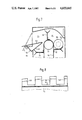
- FIG. 7 is a sectional view of the upper portion of the bobbin magazine of FIG. 5A, at an enlarged scale and showing in more detail the arrangement that enables the extraction of the bobbin tubes from the magazine;
- FIG. 8 is a fragmentary view of a detail of FIG. 7, drawn to a different scale
- FIG. 9 is a cross-sectional view of an arrangement in the service device which receives the bobbins from the magazine and prepares them for transfer to individual operating stations;
- FIG. 10 is a diagrammatic end elevational view of a modified construction of the bobbin magazine of the invention.
- FIG. 11 is a view of one detail of FIG. 10.
- FIG. 12 is a view of another detail of FIG. 10.
- FIG. 1 diagrammatically illustrates a rotor spinning machine which comprises end heads 10 and 12 and two rows of spinning units 14 respectively extending along opposite sides of the spinning machine between the end heads 10 and 12.
- This general machine layout, and the construction of the individual spinning units or stations 14 is now very well known in the yarn spinning art, and hence will not be described further herein. Further details of one machine construction based on this layout may be seen in the U.S. Pat. No. 3,375,649, but the present invention is by no means limited to use with that particular machine construction.
- Yarn newly spun at each spinning station 14 is wound up into a respective yarn package at that station.
- the package is transferred from the spinning station 14 to a conveyor belt 16 extending longitudinally of the machine between the rows of spinning stations 14.
- the package is then carried by the belt 16 to one machine end where it can be collected and passed on to a package handling system chosen by the operating spinning mill. Transfer of the package from the spinning station 14 to the belt 16 is effected by an automatic doffer which forms one unit of a multi-purpose service device indicated at 18 in FIG. 1.
- the device 18 is suspended from a U-shaped rail 20 and can move in any desired direction along the rail 20 past the spinning stations 14. When all spinning stations 14 are operating normally, the device 18 performs "patrolling" movements from one rail end to the other past both machine sides. The device 18 is, however, continually inspecting the stations 14, and when it senses that an "event” has occurred at one of these stations 14, it stops in front of that station 14 and performs an appropriate service operation on the "calling" station. Doffing of a completed yarn package is one such operation. "Piecing" of a broken yarn may be another such operation.
- the service device 18 may also be designed to perform "preventive maintenance" involving a temporary interruption of spinning in order to clean the rotor at the spinning station 14 involved.
- the device 18 advantageously comprises a plurality of other automatically operating units, for example a yarn piecing unit, a rotor cleaning unit and a locating system designed to control the positioning of the device 18 relative to the spinning machine.
- a yarn piecing unit for example a yarn piecing unit, a rotor cleaning unit and a locating system designed to control the positioning of the device 18 relative to the spinning machine.
- a locating system designed to control the positioning of the device 18 relative to the spinning machine.
- FIGS. 2 and 3 show in a considerably simplified manner the structure of the service device 18.
- the device 18 has been illustrated and will be described for use with the machine constructed and operated for winding cylindrical packages or "cheeses”.
- a modification of a bobbin magazine to enable use with a machine for winding "cones" will then be described with reference to subsequent Figures of the drawing.
- FIGS. 2 and 3 The structure shown in FIGS. 2 and 3 is illustrated primarily in order to show the importance of space utilization in a multi-purpose device of this type. Accordingly, it is believed unnecessary to describe details of the illustrated devices, and attention will be concentrated upon the overall layout of the various automatic units in the service device 18. Details of some of the automatic units can, however, be obtained from the copending patent applications referred to above.
- the main structural member in the device 18 is a carrier beam 22 which is mounted on the rail 20 by a suspension 24 and a drive unit 26, respectively, from which all other parts of the service device are suspended.
- Two further major structural elements are constituted by respective vertical bulk heads 28 and 30 which respectively divide the device 18 into left-hand, right-hand and center sections as considered in FIG. 2.
- the main automatic operating units are provided in the center section.
- a lowermost (“first") group 32 comprises units adapted to cooperate directly with the spinning components at a spinning station 14 being serviced;
- a second group 34 comprises units adapted to handle a yarn during threading thereof into the machine for a piecing operation;
- a third group 36 comprises units adapted to present a yarn to the second group 34 (for example, the group 36 comprises a suction nozzle 38 for finding a broken yarn end on a package at a spinning station 14 being serviced);
- a fourth group 40 comprises units used during doffing and during insertion of a fresh bobbin tube into a spinning station 14 to replace a package doffed therefrom;
- a fifth, and uppermost, group 42 comprises a system for feeding bobbin tubes to the group 40.
- the left-hand section of the device 18 contains drive and control systems for the various units 32, 34, 36, 40 and 42 in the center section.
- the right-hand section contains primarily a suction system comprising an air pump 44 and a reservoir 46 the interior of which is held at low pressure by the air pump 44 and provides corresponding low pressure to various pneumatic systems in the center section of the device 18.
- the main bulk of the device 18 is contained within a generally boxlike envelope of a rectangular vertical cross section delimited by two end plates 48 and 50 respectively, the end plate 48 being also shown in FIG. 4. Bars 52 secured to these end plates 48 and 50 are safety devices intended to stop travel of the device 18 if one of the bars 52 contacts an obstruction.
- the outwardly-facing side that is, the side facing away from the machine
- the device 18 has a protective panelling 54, but the device 18 is open at its side facing the machine. At its lower edge on that side, the device 18 has rollers 56 to engage guide rails provided on the machine itself.
- the device 18 is fitted at its upper end with certain parts which project inwardly over the machine. These parts include an energy pick-up 58 by means of which energy can be derived from the machine to operate the device 18.
- an energy pick-up 58 by means of which energy can be derived from the machine to operate the device 18.
- a bobbin magazine 60 the floor of which is in the form of a simple inclined plane sloping from the center of the machine to a vertically disposed chute 62.
- Cylindrical bobbin tubes can roll down the inclined plane and drop vertically down the chute 62 to be held by a pair of legs 64 (FIG. 2) at the lower end of the chute 62.
- the new magazine is to be attached to one end of the service device 18. In the illustrated embodiment, this is effected by securing the magazine to the end plate 48.
- the new magazine should remain as far as possible within the cross-sectional envelope defined by the end plate 48, but in order to maximize the available storage space it is desirable to utilize the entire cross section represented by that end plate 48. This gives rise to a problem, however, in that (as seen in FIG. 4) the plate 48 has a plurality of openings 68 enabling limited access to the drive systems in the left-hand section of the device 18 as viewed in FIG. 2. These openings 68 enable insertion of operating tools by means of which the drives can be operated manually in the event of a malfunction, during testing or for other reasons.
- the bobbin magazine is to be secured to the plate 48 in a manner enabling it to move relative to the plate 48 while remaining secured thereto.
- the magazine can be moved between an operating position, in which it conceals the plate 48, and a non-operating position in which plate 48 is exposed.
- FIG. 5A represents a vertical section as viewed from one side
- FIG. 5B represents a top plan view
- the new magazine 70 is a generally box-like structure the dimensions of which in end view (not shown) correspond closely (but not necessarily exactly) to those of the plate 48.
- the magazine 70 is secured to the plate 48 (after removal of the safety bar 52 therefrom) by means of a hinge 72 provided along the entire length of the outer edge of plate 48, that is the edge furthest from the machine.
- a suitable releasable catch mechanism 74 (FIG.
- the magazine 70 in its operating position relative to the device 18 in which one end wall 88 of the magazine 70 lies in a plane parallel to and adjacent the plate 48.
- the magazine 70 can be operated (by means to be described below) to transfer bobbins from the magazine 70 to the main part of the device 18.
- the catch 74 can be released and the magazine 70 can be swung about a vertical axis passing through the hinge 72 into a position in which the end wall 88 lies at right angles to the plate 48 as viewed in FIG. 5B.
- the main operating element of the magazine 70 is best seen in FIG. 5A and comprises an endless belt 76 running around upper and lower drive and guide pulleys 78 and 80, respectively.
- Each of the pulleys 78 and 80 is mounted (by means not shown) to be rotatable about a generally horizontal axis in a counter-clockwise direction as viewed in FIG. 5A.
- the right-hand vertical run of the belt 76 travels upwardly and the left-hand vertical run travels downwardly.
- a plurality of compartment-defining elements 82 is secured to the band 76 so that the elements 82 are evenly spaced along the band 76.
- Each element 82 is Y-shaped in cross-section, the main leg of the Y being elongated and attached to the band 76 at its foot.
- a compartment 84 is defined between each successive pair of the elements 82.
- Each compartment 84 is elongated with the longitudinal axis of the compartment 84 lying parallel to the width of the band 76, that is, substantially horizontally. The length of each compartment 84 is sufficient to hold a "stick" of telescoped, conical bobbin tubes 86 with a predetermined number of tubes 86 in the stick, for example eight tubes 86 as shown in FIG. 5B.
- each compartment 84 is dimensioned to leave adequate clearance around the bobbin tubes 86 (FIG. 5A) of predetermined maximum external diameter.
- the heads of the Y-shaped elements 82 serve to retain the sticks of the tubes 86 in their respective compartments 84 after they have been loaded into the magazine 70 and to prevent rubbing against vertical end walls 88 and 89 of the magazine 70.
- the stick of tubes 86 accommodated in that compartment 84 is permitted to roll on a curved guide plate 90 (FIG. 5A) which forms the lowermost surface of the magazine 70.
- a hatch 91 in the guide plate 90 can be released to permit unloading of the magazine 70 by hand, if required.
- the magazine 70 is illustrated in FIG. 5 in a condition in which it is being loaded from the completely empty state. It will be assumed that the loading of the magazine 70 is effected manually, although it is also contemplated to effect automation of this loading step.
- a door 92 (FIG. 5B) supported on a hinge 93 arranged at the side of the magazine 70 facing away from the machine is opened. This provides access to the compartments 84 so that it is easy to insert a stick of the tubes 86 by axial movement thereof.
- a drive (not shown) can drive the belt 76 in the counter-clockwise direction, or the system can be driven manually, so as to enable insertion of the sticks of the tubes 86 into the respective compartments 84 near the lower end of the elevator.
- the endless belt 76 defines a closed path of movement for the compartments 84, and in FIG. 5A it is assumed that the first-inserted stick of tubes 86 has passed along this path to a stage at which it is ready to pass from the upward to the downward run of the belt 76.
- the compartment 84 at the upper end of the downward run of the belt 76 is thereby slightly enlarged, so that this is in a suitable position along the path of travel to effect removal of the sticks of the tubes 86 from the magazine 70. Removal means operating at this point in the path will be described later. In the assumed circumstances, however, in which the magazine 70 is being loaded, the removing system is rendered inoperative and effectively closes off the casing of the magazine 70 as illustrated in FIG. 5A. Thus the loading operation can continue, with passage of the already loaded sticks of the tubes 86 from the upward to the downward run of belt 76, and the service device 18 can finally be sent into service operation with a stick of the tubes 86 in each compartment 84 of its magazine 70.
- the general advantages of this arrangement can be seen in FIG. 5.
- the total length of the device 18 in its direction of travel is increased (by addition of the magazine 70) by little more than twice the maximum bobbin external diameter plus the diameter of the pulleys 78 and 80.
- virtually the full cross-sectional area of the device 18 is exploited by each of the two runs of the belt 76.
- the full width of the belt 76, and hence almost the full width of the device 18, can be exploited for storage purposes.
- the magazine 70 can be provided with its own separate suspension for cooperation with the rail 20, and a tow connection can be provided between the device 18 and the separately suspended magazine 70.
- FIG. 6A illustrates once again in highly diagrammatic form the upper portion of the magazine 70; in this case, no attempt has been made to represent the actual physical structure involved since only the operating principle is of interest in FIG. 6.
- a construction enabling the principles of FIG. 6 to be put into effect will be described later with reference to FIGS. 7 to 9. Similar remarks apply to other elements shown in FIG. 6B which are provided on the service device 18.
- a pivotable door 92 is provided in the upper portion of the casing wall 88 facing the end plate 48.
- the door 92 is pivoted to a closed position (shown in dotted lines in FIG. 6A),it closes the casing of the magazine 70 so that no tubes 86 are extracted, for example during loading as described with reference to FIG. 5A.
- a stick 94 of tubes 86 in the compartment 84 then situated at the upper run of the belt 76 can roll out of the compartment 84 and down the inclined door 92 into the service device 18.
- the box 96 is mounted on a carrier 98 which is pivotable about a vertical axis defined by a pivot pin 100.
- the carrier 98 can be pivoted through a quarter-circle, so that the box 96 adopts the dotted line position shown in FIG. 6B.
- the complete stick 94 is therefore now oriented longitudinally of the machine (and of the direction of travel of the device 18).
- the tube separating device 102 is of a generally known type, similar to that described in the U.S. Pat. No. 4,066,218. Accordingly, only the broad principles will be described in this description.
- the device 102 is shown in its condition of readiness to separate a "first" or “leading” tube 86L of the stick 94 from the rest of the stick 94.
- the second tube of the stick 94 is clamped adjacent its maximum diameter end ("foot") by a pair of clamping elements 104.
- a separator finger 106 engages the axial end face on the foot of the leading tube 86L.
- the finger 106 is pivoted at 108, and when the finger 106 is pivoted in a clockwise direction (as viewed in FIG. 6) around its pivot 108, it urges the tube 86L to the left and away from the clamped tube 86 and the remainder of the stick 94.
- the finger 106 has only a short stroke of movement, sufficient to ensure that the leading tube 86L is freed from the remainder of the stick 94.
- the movement of the freed tube 86L to the upper end of the chute 62 is effected by a pusher 110 which also engages the axial end face at the foot of the leading tube 86L but which has a relatively long operating stroke compared with that of the finger 106.
- the leading tube 86L When the leading tube 86L reaches the chute 62, it falls into the chute 62 and onto a releasable control plate (not shown). When the plate is moved to unblock the chute 62, the tube 86L can fall onto the holder legs 64 (see also FIG. 2) ready for collection by the inserting element 66 (FIG.2). Details of the chute 62 are provided in the U.S. patent application Serial No. 611,852 referred to above, and form no part of the present invention, so that further description will be confined to the system only up to the pusher 110.
- the door 92 is operated by a cylinder-and-piston unit 118 which is spring-biased to urge the door 92 into its closed condition in which the bobbin tubes 86 cannot be extracted from the magazine 70.
- the box 96 is moved by a cylinder-and-piston unit 120 which is spring-biased to urge the box 96 into its position to receive a stick 94 of the tubes 86 falling from the door 92.
- the clamping elements 104 are operated by a double-acting cylinder-and-piston unit 122, and the pivotable end stop 114 is operated by the same unit 122 because of the linkage described above.
- the finger 106 and the pusher 110 are operated by respective, individual, double-acting cylinder-and-piston units 124 and 126, respectively, the unit 126 having a substantially longer operating stroke than the unit 124.
- a biasing spring urging the forwarding member 116 to the left as viewed in FIG. 6 is indicated at 128 and the forwarding member 116 can be withdrawn to a "full-right" position against the bias of the spring 128 by means of a single-acting cylinder-and-piston unit 130.
- the control of the pressurization of the unit 118 is effected by a valve V1.
- the control of the pressurization of the unit 120 is effected by a valve V2.
- the control of the pressurization of the unit 130 is effected by a valve V3.
- the control of the pressurization of the double-acting units 122, 124 and 126 is effected by respective valves V4, V5 and V6.
- FIG. 7 substantially corresponds to FIG. 5A and thus most elements will not need detailed description.
- the pivotable door 92 has a head portion providing a closure face 132 and a extractor face 134.
- the face 132 forms a continuation of the casing wall 88 so that the sticks 94 of the tubes 86 are retained in the magazine 70.
- the face 134 provides an inclined plane projecting into the uppermost compartment 84 on the downward run of belt 76 to enable extraction of the respective stick 94 of the tubes 86 as already described above with reference to FIG. 6.
- the free ends of the elements 82 are provided with recesses 136 (FIG. 8) so that the head of each element 82 is not continuous across the entire width of the belt 76 but is constituted by a plurality of projecting fingers 138.
- the left hand finger 138 is shorter to allow for the conicity of the foremost tube 86L in the stick 94.
- the head portion on the door 92 is made correspondingly discontinuous so that the fingers (not shown) on the door 92 correspond to the recesses 136 in the elements 82.
- the clearances are made such that the elements 82 can pass by the door 92 without interference.
- a stick 94 of the tubes 86 carried by an element 82 passing from the upward to the downward run of the belt 76 will extend longitudinally across the fingers of the door 92 and will be collected thereby as the corresponding compartment 84 reaches the downward run of the belt 76.
- the belt 76 can then be driven at any time that the door 92 is closed, for example for inspection or loading operations. In order to avoid complications, no particular steps are taken to ensure that the belt 76 stops in any particular disposition relative to the door 92. Accordingly, when an attempt is made to open the door 92, there may be a stick 94 of the tubes 86 resting on the uppermost element 82 on the downward run of the belt 76 and this stick 94 will then interfere with the opening of the door 92. Means can be provided to sense such interference and to cause the belt 76 to move forward sufficiently to permit the opening of the door 92.
- FIG. 9 shows the carrier beam 22 and a horizontal plate 140 supported (by means not shown) slightly above the beam 22 when the device 18 is suspended from the rail 20 in use.
- the plate 140 carries a boss 142 rotatably supporting the pivot pin 100 that has been previously mentioned in connection with FIG. 6.
- the carrier 98 (see also FIG. 6) is mounted on the pin 100 so that the box 96 (see also FIG. 6) is spaced slightly from the plate 140 for movement relative to the plate 140 without interference.
- the position illustrated in FIG. 9 corresponds to the dotted line position in FIG. 6, that is, with the length of the elongated box 96 aligned with the direction of travel of the device 18.
- the box 96 is open-topped so that it can receive a stick 94 falling from the door 92.
- the box 96 also has no bottom, so that the stick 94 falls directly onto the plate 140.
- the position of the stick 94 relative to the plate 140 is, however, restrained by the side walls of the box 96.
- the stick 94 is forced to slide over the plate 140.
- the plate 140 has an opening 144 in alignment with and dimensioned to correspond with the box 96 when the latter is in the position shown in FIG. 9.
- the stick 94 of the tubes 86 thus falls through the opening 144 in the plate 140 into a short chute 146.
- the stick 94 first falls and then rolls down the wall of the chute 146 until it hits a stop wall 148 approximately at the elevation of the carrier beam 22. In this position, the stick 94 is at rest in the separator device 102. At this time, the forwarding member 116 is fully withdrawn (to the right as shown in FIG. 6B) to ensure that the stick 94 of the tubes 86 can roll into the required position in the separator 102 without interference from the forwarding member 116.
- the cylinder-and-piston unit 130 is operated to move the forwarding member 116 forward (to the left as viewed in FIG. 6B) so as to urge the stick 94 of the tubes 86 forward until the front tube 86L engages the retainer 114. In this position, as shown in FIG. 6B, the pusher 110 engages just behind the foot of the foremost tube 86L.
- the pusher 110 extends through an opening 150 forming a guideway in the wall 148.
- the pusher 110 has a shaped lip 152 which enables it to engage behind the foot of the foremost tube 86L without interference with the second tube 86 (if any) in the stick 94.
- the pusher 110 must ride over the foot of the next tube 86 in the stick 94 which in the meanwhile will have moved forward into engagement with the retainer 114.
- means is provided to enable the pusher 110 to move radially outwardly relative to the stick 94 of the tubes 86 in order to enable it to ride over the foot of the respective next tube 86.
- the cylinder of the unit 126 has a pivot mounting 154 at its end remote from the pusher 110.
- the mounting arrangement 154 cooperates with a corresponding portion (not shown) secured in the frame of the device 18 to enable the cylinder of the unit 126 to pivot about an axis contained within the mounting arrangement 154 and extending at right angles to the plane of the drawing in FIG. 6B.
- a compression spring 156 is provided extending between the frame and the cylinder, urging the latter in a clockwise direction (as viewed in FIG. 6B) around the pivot axis in the mounting arrangement 154.
- a suitable stop (not shown) is provided to limit this "clockwise" rotation of the unit 126 and thus to limit the movement of the lip 152 of the pusher 110 towards the stick 94 of the tubes 86.
- the stop is positioned to permit the pusher 110 to engage behind a tube foot as illustrated in FIG. 9.
- the cylinder-and-piston unit 126 can swing counter-clockwise (as viewed in FIG. 6B) around the pivot axis in the mounting arrangement 154 against the bias of a compression spring 156.
- the spring 156 again urges the unit 126 in a clockwise direction so that the pusher 110 engages behind the tube foot.
- the unit 126 can pivot on the mounting arrangement 154 to permit the pusher 110 to ride over the foot of the foremost tube 86L.
- each compartment 84 is formed by a C-shaped element 160 secured to the belt 76 at a location on the C diametrically opposite the opening therein.
- the major difference with respect to the first embodiment is to be seen in the disposition of the axes of the belt drive pulleys 78 and 80--and hence the longitudinal axes of the compartments 84. As seen in the end elevation in FIG. 10, these axes now extend at right angles to the end face 88 which is parallel to the end plate 48 (FIG. 4) of the service device 18.
- the end plate 48 cannot be seen in FIG. 10 because it is concealed behind the plate which forms the magazine end face 88.
- the plate 88 forms a support and mounting structure for the magazine 70, being secured at its left hand edge (as viewed in FIG. 10) to the end plate 48 by a hinge arrangement (not seen in FIG. 10) similar to the hinge 72 shown in FIG. 5A.
- Hook elements the heads of which can be seen at 162 in FIG. 10, extend from the service device 18 through openings 164 in the plate 88 and secure the latter in its operating position parallel to the plate 48.
- the catches formed by the hooks can be released to permit the plate 88 to be swung away from the plate 48 to expose the latter.
- the pulleys 78 and 80 project in a cantilever fashion from the mounting plate 88.
- the plates 48 and 88 each also have an inverted L-shaped opening 166 through which the sticks 94 of the tubes 86 (not shown in FIG. 10) can be transferred from the magazine 70 into the service device 18 by movement longitudinally of the compartment (and stick/tube) axes. This transfer is effected by a runner 168 reciprocable on a rail 170 mounted in the service device 18 and extending parallel to the compartment/stick axes.
- the runner 168 carries an arm 172 projecting downwardly therefrom on the side facing the compartments 84. At its lower end, the arm 172 carries a spring finger 174 which, as shown in FIG. 10, can project into the compartment 84 of a suitably located element 160.
- the rail 170 extends sufficiently far out from the plates 48 and 88 to enable the runner 168 to carry the spring finger 174 past the outboard end (i.e. the end remote from the plate 88) of a stick 94 of the tubes 86 carried by the compartment 84 in the unloading position (i.e. the position in which the finger 174 projects into that compartment 84).
- the runner 168 is retracted so that the finger 174 is contained within the service device 18.
- the runner 168 is moved outwardly along the rail 170 carrying the finger 174 to its outboard position, past the stick 94 of the tubes 86. As seen in FIG.
- the arm 172 lies wholly outside the element 160, only the finger 174 projecting into the compartment 84.
- the finger 174 engages the tubes 86 in the compartment 84 as it moves past them.
- the stick 94 must be so oriented that the tips of the tubes 86 (the narrower ends) lie closer to the plate 88 than their wider ends.
- the spring in the finger 174 enables it to move outwardly over the foot of each tube 86 in the stick 94 until it engages behind the foot of the outboard tube 86 in the stick 94.
- the finger 174 engages the foot of the outboard tube 86 and draws the stick 94 into the service device 18 where it is received by a channel-shaped receiver element (not seen in FIG. 10).
- a suitable runner and rail structure 168 and 170 is supplied by Festo Maschinenfabrik G. Stoll, D-73 Esslingen 1, Berkheim, West Germany, under the type number DFO-PPV-A.
- FIG. 11 shows in section a detail of the system described with reference to FIG. 10, namely the element 160 in the unloading position.
- the element 160 is secured to the belt 76 by rivets 176.
- a sensor device 178 is located adjacent the belt 76 to respond to the heads of the rivets 176.
- the sensor device 178 provides a signal to a microprocessor control system (not shown) which controls the operation of a drive motor (not shown) rotating the pulley 78.
- the drive motor can be provided in the service device 18 and a connector drive shaft (not shown) then extends through the plates 48 and 88 to the pulley 78.
- each C-shaped element 160 Secured to the interior of each C-shaped element 160 opposite the opening therein is a reflector 180.
- a photosensor device 182 having a light beam emitter and receiver is located opposite the opening of the C-shaped element 160 so that the beam from the device 182 is reflected by the reflector 180 if the compartment 84 situated in the unloading position is empty.
- the drive motor referred to above can then be operated again by the microprocessor control to move the belt 76 along until a full compartment 84 is in the unloading position. Then, the light beam from the device 182 cannot reach the reflector 180 because of the intervening stick 94 of the tubes 86 indicated in dotted lines in FIG. 11.
- the C-shaped element 160 extends sufficiently far around the periphery of the sticks 94 of the tubes 86 to ensure that the stick 94 is retained by the element 160 as the latter passes around the lowermost part of the path defined by the belt 76.
- a housing around the elevator formed by the belt 76 and pulley system 78 and 80 can be omitted.
- a retainer plate can be mounted on the outboard ends of the shafts (not shown) of the pulleys 78 and 80.
- Such a plate could extend from the top to the bottom of the elevator, extending part-way across the cross section of each compartment 84--for example as far as a dotted line 184 indicated in FIG. 11.
- Loading of the sticks 94 can be effected by distorting the belt 76 in the direction of an arrow 185 to a degree sufficient to move the section of one compartment 84 to a position clear of the retainer plate as viewed in end elevation. This enables insertion of a stick 94 by movement along the compartment axis.
- the belt 76 must of course have the necessary flexibility. Such loading can be performed by hand.
- FIG. 12 shows in sectioned plan view a further detail of the system shown in FIG. 10, namely at the region of the plates 48 and 88.
- the runner 168 is assumed to be moving towards the outboard end of the rail 170 (downwardly as viewed in FIG. 12) and the finger 174 is about to engage the tip of the inboard tube 86 of the stick 94 in the compartment 84 to be unloaded.
- the finger 174 can be formed as a leaf spring secured to the arm 172 at its outboard end and forming a "wedge" increasing in size in the inboard direction.
- the inboard end of the spring 174 is bent to pass through a slot 186 in the arm 172. As the wedge structure provided by the spring 174 engages the tip of the tube 86, the bent end of the spring 174 is forced through the slot 186 so that the wedge effect is reduced and the spring 174 rides over the tube 86.
- FIG. 12 also shows one side wall and the bottom of a receiver channel 188 provided in the service device 18, the other side wall being hidden beneath the rail 170.
- the channel 188 extends as far as the top of the chute 62 (FIG. 3) into which the bobbin tubes 86 can be pushed by movement along the channel 188 after they have been separated from the stick 94.
- a separating mechanism identical with that described with reference to FIG. 6 is located in a separating zone (not shown) of the channel 188 between the chute 62 and the channel portion shown in FIG. 12.
- the rail 170 extends at least so far into the service device 18 that the arm 172 can draw a stick 94 of the tubes 86 into the separating zone.
- the arm 172 could also be used to draw separated tubes 86 from the separating zone to the chute 62, but this would necessitate the provision of additional means to operate the spring 174 to enable it to pass the stick 94 in the separating zone to a position at which it could engage behind a separated tube 86. It will often be simpler to use the separate pusher 110 (FIG. 6) for this purpose. As can be seen from FIG. 12, the arm 172 is bent below the runner 168 and extends outboard therefrom, so that the rail 170 needs to extend only part-way along each compartment 84.
Landscapes
- Spinning Or Twisting Of Yarns (AREA)
- Replacing, Conveying, And Pick-Finding For Filamentary Materials (AREA)
- Unwinding Of Filamentary Materials (AREA)
Priority Applications (9)
| Application Number | Priority Date | Filing Date | Title |
|---|---|---|---|
| US06/698,628 US4655665A (en) | 1985-02-06 | 1985-02-06 | Bobbin magazine for a travelling service device of a yarn processing machine |
| EP88119953A EP0313108B1 (fr) | 1985-02-06 | 1985-11-27 | Magasin de bobines pour un ensemble fonctionnel se déplaçant le long d'une machine de traitement de fil |
| DE8888119953T DE3581217D1 (de) | 1985-02-06 | 1985-11-27 | Spulenmagazin fuer eine hin- und herfahrende bedienungseinrichtung an einer garnbe- oder verarbeitungsmaschine. |
| EP85115051A EP0190421B1 (fr) | 1985-02-06 | 1985-11-27 | Ensemble fonctionnel se déplaçant le long d'une machine de traitement de fil |
| DE8585115051T DE3576487D1 (de) | 1985-02-06 | 1985-11-27 | Hin- und herfahrende bedienungseinrichtung an einer garnbe- oder -verarbeitungsmaschine. |
| IN977/MAS/85A IN165817B (fr) | 1985-02-06 | 1985-12-03 | |
| CN85109416A CN1014808B (zh) | 1985-02-06 | 1985-12-28 | 一种纱线加工机的维护操作工位的操作装置 |
| JP61011196A JPS61186535A (ja) | 1985-02-06 | 1986-01-23 | 糸処理機械の走行型サービス装置用ボビンマガジン |
| IN234/MAS/89A IN169298B (fr) | 1985-02-06 | 1989-03-23 |
Applications Claiming Priority (1)
| Application Number | Priority Date | Filing Date | Title |
|---|---|---|---|
| US06/698,628 US4655665A (en) | 1985-02-06 | 1985-02-06 | Bobbin magazine for a travelling service device of a yarn processing machine |
Publications (1)
| Publication Number | Publication Date |
|---|---|
| US4655665A true US4655665A (en) | 1987-04-07 |
Family
ID=24806032
Family Applications (1)
| Application Number | Title | Priority Date | Filing Date |
|---|---|---|---|
| US06/698,628 Expired - Fee Related US4655665A (en) | 1985-02-06 | 1985-02-06 | Bobbin magazine for a travelling service device of a yarn processing machine |
Country Status (6)
| Country | Link |
|---|---|
| US (1) | US4655665A (fr) |
| EP (2) | EP0190421B1 (fr) |
| JP (1) | JPS61186535A (fr) |
| CN (1) | CN1014808B (fr) |
| DE (2) | DE3581217D1 (fr) |
| IN (1) | IN165817B (fr) |
Cited By (10)
| Publication number | Priority date | Publication date | Assignee | Title |
|---|---|---|---|---|
| US4772171A (en) * | 1985-10-16 | 1988-09-20 | Walter Mayer | Process and device to feed conical tubes to the pirn heads of a textile machine |
| US4781338A (en) * | 1986-07-18 | 1988-11-01 | Rieter Machine Works, Ltd. | Bobbin tube support |
| US4883231A (en) * | 1987-09-02 | 1989-11-28 | Vyzkumny Ustav Bavlnarsky | Cop tube transporting device for textile machines |
| US5159805A (en) * | 1990-04-03 | 1992-11-03 | Rieter Machine Works, Ltd. | Guide arrangement for peg trays on a ring spinning machine |
| US5169274A (en) * | 1990-03-30 | 1992-12-08 | Ceeco Machinery Manufacturing Limited | Bobbin sorting and batch transfer apparatus |
| WO1992021592A1 (fr) * | 1991-05-31 | 1992-12-10 | Syncro Machine Company | Triage de bobines et appareil de transfert par lots |
| US5273224A (en) * | 1991-05-28 | 1993-12-28 | Murata Kikai Kabushiki Kaisha | Doffing method and paper tube supply system for an automatic winder |
| US5765356A (en) * | 1996-03-07 | 1998-06-16 | Rieter Ingolstadt Spinnereimaschinenbau Ag | Spinning machine tube transport and removal system |
| KR100352231B1 (ko) * | 2000-03-09 | 2002-09-12 | 송철수 | 섬유용 보빈의 잔사 제거장치 |
| CN117262902A (zh) * | 2022-06-22 | 2023-12-22 | 日本Tmt机械株式会社 | 筒管输送系统以及筒管输送方法 |
Families Citing this family (9)
| Publication number | Priority date | Publication date | Assignee | Title |
|---|---|---|---|---|
| IT1197301B (it) * | 1986-09-29 | 1988-11-30 | Savio Spa | Apparecchiatura e procedimento per addurre tubetti avvolgitori alle singole stazioni di raccolta di una macchina tessile. |
| DE10251623A1 (de) * | 2002-11-06 | 2004-05-19 | Rieter Ingolstadt Spinnereimaschinenbau Ag | Verfahren und Vorrichtung zum Warten von Aggregaten einer Spinnmaschine |
| JP2004250140A (ja) * | 2003-02-19 | 2004-09-09 | Murata Mach Ltd | コーン型ボビン供給装置 |
| CN102242429B (zh) * | 2011-06-11 | 2013-03-06 | 江阴市华方新技术科研有限公司 | 纱筐自动更换装置 |
| CN103979370B (zh) * | 2014-05-23 | 2017-03-01 | 启东腾飞企业管理服务有限公司 | 一种纱管供给装置 |
| CZ2017674A3 (cs) * | 2017-10-24 | 2019-05-02 | Rieter Cz S.R.O. | Způsob řízení obslužného zařízení pracovního místa textilního stroje pro výrobu příze a textilní stroj |
| DE102018132462A1 (de) * | 2018-12-17 | 2020-06-18 | Saurer Spinning Solutions Gmbh & Co. Kg | Kreuzspulen herstellende Textilmaschine mit einer Kreuzspulentransporteinrichtung |
| CN111960189B (zh) * | 2020-08-31 | 2024-08-02 | 四川大学 | 自动卷纱设备 |
| DE102020122952A1 (de) * | 2020-09-02 | 2022-03-03 | Trützschler GmbH & Co Kommanditgesellschaft | Verfahren zum Betreiben eines Kannenwechslers, Kannenwechsler und Textilmaschine |
Citations (12)
| Publication number | Priority date | Publication date | Assignee | Title |
|---|---|---|---|---|
| US2437425A (en) * | 1945-12-19 | 1948-03-09 | United Shoe Machinery Corp | Ammunition container |
| US2886940A (en) * | 1956-06-16 | 1959-05-19 | Kanegafuchi Spinning Co Ltd | Apparatus for automatically mounting and dismounting a bobbin for a spinning machine, a twister and the like |
| US3082908A (en) * | 1958-10-13 | 1963-03-26 | Deering Milliken Res Corp | Bobbin handling arrangement |
| US3154909A (en) * | 1959-09-26 | 1964-11-03 | Kanegafuchi Spinning Co Ltd | Apparatus for automatically exchanging bobbins in spinning machines |
| DE2131957A1 (de) * | 1971-06-26 | 1973-02-01 | Barmag Barmer Maschf | Vorrichtung zum foerdern konischer huelsen |
| US3939634A (en) * | 1974-01-03 | 1976-02-24 | Kabushiki Kaisha Toyoda Jidoshokki Seisakusho | Empty bobbin supply device |
| US4066218A (en) * | 1974-09-27 | 1978-01-03 | W. Schlafhorst & Co. | Method and device for supplying empty conical coil cores to the individual winding stations of a textile machine |
| GB2129451A (en) * | 1982-11-06 | 1984-05-16 | Reiners Verwaltungs Gmbh | Spool tube magazine |
| EP0126352A2 (fr) * | 1983-05-20 | 1984-11-28 | Maschinenfabrik Rieter Ag | Disposition de mise en place de support de bobines |
| EP0126373A2 (fr) * | 1983-05-24 | 1984-11-28 | Maschinenfabrik Rieter Ag | Dispositif automatique de "positionnement" |
| EP0127017A1 (fr) * | 1983-05-20 | 1984-12-05 | Maschinenfabrik Rieter Ag | Dispositif de rattachement pour une machine de filature à bout libéré |
| US4564123A (en) * | 1982-10-01 | 1986-01-14 | Murata Kikai Kabushiki Kaisha | Magazine driving device in paper tube releasing apparatus |
Family Cites Families (2)
| Publication number | Priority date | Publication date | Assignee | Title |
|---|---|---|---|---|
| DE2037826A1 (de) * | 1970-07-30 | 1972-04-06 | Barmag Barmer Maschinenfabrik Ag, 5600 Wuppertal | Vorrichtung zum selbsttätigen Beschicken von Spulenhaltern, insbesondere an Textilmaschinen |
| US4081949A (en) * | 1977-01-28 | 1978-04-04 | Automatic Material Handling, Inc. | Doffer with pneumatic control system |
-
1985
- 1985-02-06 US US06/698,628 patent/US4655665A/en not_active Expired - Fee Related
- 1985-11-27 EP EP85115051A patent/EP0190421B1/fr not_active Expired
- 1985-11-27 EP EP88119953A patent/EP0313108B1/fr not_active Expired
- 1985-11-27 DE DE8888119953T patent/DE3581217D1/de not_active Expired - Lifetime
- 1985-11-27 DE DE8585115051T patent/DE3576487D1/de not_active Expired - Lifetime
- 1985-12-03 IN IN977/MAS/85A patent/IN165817B/en unknown
- 1985-12-28 CN CN85109416A patent/CN1014808B/zh not_active Expired
-
1986
- 1986-01-23 JP JP61011196A patent/JPS61186535A/ja active Pending
Patent Citations (12)
| Publication number | Priority date | Publication date | Assignee | Title |
|---|---|---|---|---|
| US2437425A (en) * | 1945-12-19 | 1948-03-09 | United Shoe Machinery Corp | Ammunition container |
| US2886940A (en) * | 1956-06-16 | 1959-05-19 | Kanegafuchi Spinning Co Ltd | Apparatus for automatically mounting and dismounting a bobbin for a spinning machine, a twister and the like |
| US3082908A (en) * | 1958-10-13 | 1963-03-26 | Deering Milliken Res Corp | Bobbin handling arrangement |
| US3154909A (en) * | 1959-09-26 | 1964-11-03 | Kanegafuchi Spinning Co Ltd | Apparatus for automatically exchanging bobbins in spinning machines |
| DE2131957A1 (de) * | 1971-06-26 | 1973-02-01 | Barmag Barmer Maschf | Vorrichtung zum foerdern konischer huelsen |
| US3939634A (en) * | 1974-01-03 | 1976-02-24 | Kabushiki Kaisha Toyoda Jidoshokki Seisakusho | Empty bobbin supply device |
| US4066218A (en) * | 1974-09-27 | 1978-01-03 | W. Schlafhorst & Co. | Method and device for supplying empty conical coil cores to the individual winding stations of a textile machine |
| US4564123A (en) * | 1982-10-01 | 1986-01-14 | Murata Kikai Kabushiki Kaisha | Magazine driving device in paper tube releasing apparatus |
| GB2129451A (en) * | 1982-11-06 | 1984-05-16 | Reiners Verwaltungs Gmbh | Spool tube magazine |
| EP0126352A2 (fr) * | 1983-05-20 | 1984-11-28 | Maschinenfabrik Rieter Ag | Disposition de mise en place de support de bobines |
| EP0127017A1 (fr) * | 1983-05-20 | 1984-12-05 | Maschinenfabrik Rieter Ag | Dispositif de rattachement pour une machine de filature à bout libéré |
| EP0126373A2 (fr) * | 1983-05-24 | 1984-11-28 | Maschinenfabrik Rieter Ag | Dispositif automatique de "positionnement" |
Non-Patent Citations (4)
| Title |
|---|
| Festo Penumatic Doppelwirkenden Zylinder, Pneumatische Linearantriebe. * |
| Festo Penumatic-Doppelwirkenden Zylinder, Pneumatische Linearantriebe. |
| P. W. Harrison, Rotor Spinning, Textile Progress, vol. 13, No. 4, pp. 7 9. * |
| P. W. Harrison, Rotor-Spinning, Textile Progress, vol. 13, No. 4, pp. 7-9. |
Cited By (11)
| Publication number | Priority date | Publication date | Assignee | Title |
|---|---|---|---|---|
| US4772171A (en) * | 1985-10-16 | 1988-09-20 | Walter Mayer | Process and device to feed conical tubes to the pirn heads of a textile machine |
| US4781338A (en) * | 1986-07-18 | 1988-11-01 | Rieter Machine Works, Ltd. | Bobbin tube support |
| US4883231A (en) * | 1987-09-02 | 1989-11-28 | Vyzkumny Ustav Bavlnarsky | Cop tube transporting device for textile machines |
| US5169274A (en) * | 1990-03-30 | 1992-12-08 | Ceeco Machinery Manufacturing Limited | Bobbin sorting and batch transfer apparatus |
| EP0530399A1 (fr) * | 1990-03-30 | 1993-03-10 | Ceeco Machinery Manufacturing Ltd. | Appareil pour assortir et transférer une suite de bobines |
| US5159805A (en) * | 1990-04-03 | 1992-11-03 | Rieter Machine Works, Ltd. | Guide arrangement for peg trays on a ring spinning machine |
| US5273224A (en) * | 1991-05-28 | 1993-12-28 | Murata Kikai Kabushiki Kaisha | Doffing method and paper tube supply system for an automatic winder |
| WO1992021592A1 (fr) * | 1991-05-31 | 1992-12-10 | Syncro Machine Company | Triage de bobines et appareil de transfert par lots |
| US5765356A (en) * | 1996-03-07 | 1998-06-16 | Rieter Ingolstadt Spinnereimaschinenbau Ag | Spinning machine tube transport and removal system |
| KR100352231B1 (ko) * | 2000-03-09 | 2002-09-12 | 송철수 | 섬유용 보빈의 잔사 제거장치 |
| CN117262902A (zh) * | 2022-06-22 | 2023-12-22 | 日本Tmt机械株式会社 | 筒管输送系统以及筒管输送方法 |
Also Published As
| Publication number | Publication date |
|---|---|
| JPS61186535A (ja) | 1986-08-20 |
| CN1014808B (zh) | 1991-11-20 |
| CN85109416A (zh) | 1986-09-10 |
| IN165817B (fr) | 1990-01-20 |
| EP0190421A2 (fr) | 1986-08-13 |
| EP0190421B1 (fr) | 1990-03-14 |
| DE3576487D1 (de) | 1990-04-19 |
| EP0313108A1 (fr) | 1989-04-26 |
| EP0190421A3 (en) | 1987-06-16 |
| DE3581217D1 (de) | 1991-02-07 |
| EP0313108B1 (fr) | 1990-12-27 |
Similar Documents
| Publication | Publication Date | Title |
|---|---|---|
| US4655665A (en) | Bobbin magazine for a travelling service device of a yarn processing machine | |
| US4576341A (en) | Cop transporting systems for an automatic winder | |
| US3295775A (en) | Method and apparatus for readying the winding operation of yarn supply coils on coil winding machines | |
| US4630435A (en) | System for automatically changing spools of a spinning machine | |
| US5311645A (en) | Can distribution apparatus | |
| US5588603A (en) | Yarn take-up tube supplying apparatus for a winder | |
| US4922707A (en) | Device to distribute sliver automatically to spinning machines | |
| US2703669A (en) | Apparatus for depositing wound yarn packages into a magazine | |
| US3774859A (en) | Bobbin handling system | |
| US4613091A (en) | Cop transporting system for an automatic winder | |
| US4079898A (en) | Doffing and donning machine | |
| US3938308A (en) | Method and device for transferring fresh bobbins from a bobbin supply device to a conveyer belt of a textile machine | |
| US4598881A (en) | Bobbin inserting device | |
| US4830171A (en) | Apparatus for providing a constant bobbin tube supply | |
| US4688735A (en) | Paper tube supply system | |
| US4660367A (en) | Bobbin transporting apparatus | |
| US4845937A (en) | Bobbin transfer system | |
| US4570865A (en) | Cop supplying device | |
| US4292712A (en) | Card coiler can changer | |
| GB2149434A (en) | Supplying package tubes in yarn winding machines | |
| US4702427A (en) | Coil producing machine | |
| US20010004999A1 (en) | Interface in the transport system of a textile machine producing cross-wound bobbins | |
| US4897991A (en) | Method and apparatus for automatic orderly removal and collection of fully-spun cops from textile ring spinning machines | |
| US5628173A (en) | Method and apparatus for feeding sliver to a spinning machine without sliver cans at spinning stations | |
| US5289674A (en) | Winding machine with an in-line package preparer, and an improved spinning-winding method |
Legal Events
| Date | Code | Title | Description |
|---|---|---|---|
| AS | Assignment |
Owner name: MASCHINENFABRIK RIETER A.G. WINTERTHUR SWITZERLAND Free format text: ASSIGNMENT OF ASSIGNORS INTEREST.;ASSIGNOR:LATTION, ANDRE;REEL/FRAME:004414/0286 Effective date: 19850207 |
|
| FEPP | Fee payment procedure |
Free format text: PAYOR NUMBER ASSIGNED (ORIGINAL EVENT CODE: ASPN); ENTITY STATUS OF PATENT OWNER: LARGE ENTITY |
|
| REMI | Maintenance fee reminder mailed | ||
| FPAY | Fee payment |
Year of fee payment: 4 |
|
| SULP | Surcharge for late payment | ||
| REMI | Maintenance fee reminder mailed | ||
| LAPS | Lapse for failure to pay maintenance fees | ||
| FP | Lapsed due to failure to pay maintenance fee |
Effective date: 19950412 |
|
| STCH | Information on status: patent discontinuation |
Free format text: PATENT EXPIRED DUE TO NONPAYMENT OF MAINTENANCE FEES UNDER 37 CFR 1.362 |