US4664236A - Electrically controlled, progressive, frictional, torque transmitting device - Google Patents
Electrically controlled, progressive, frictional, torque transmitting device Download PDFInfo
- Publication number
- US4664236A US4664236A US06/774,972 US77497285A US4664236A US 4664236 A US4664236 A US 4664236A US 77497285 A US77497285 A US 77497285A US 4664236 A US4664236 A US 4664236A
- Authority
- US
- United States
- Prior art keywords
- clutch
- transmitting device
- frictional
- torque transmitting
- torque
- Prior art date
- Legal status (The legal status is an assumption and is not a legal conclusion. Google has not performed a legal analysis and makes no representation as to the accuracy of the status listed.)
- Expired - Fee Related
Links
- 230000000750 progressive effect Effects 0.000 title abstract description 8
- 229910000831 Steel Inorganic materials 0.000 claims description 6
- 230000005684 electric field Effects 0.000 claims description 6
- 239000010959 steel Substances 0.000 claims description 6
- 239000012530 fluid Substances 0.000 description 21
- 230000004044 response Effects 0.000 description 5
- 239000006247 magnetic powder Substances 0.000 description 4
- 230000008901 benefit Effects 0.000 description 3
- 239000004677 Nylon Substances 0.000 description 2
- 230000003321 amplification Effects 0.000 description 2
- 238000004364 calculation method Methods 0.000 description 2
- 238000001816 cooling Methods 0.000 description 2
- 239000003822 epoxy resin Substances 0.000 description 2
- 239000012212 insulator Substances 0.000 description 2
- 239000007788 liquid Substances 0.000 description 2
- 230000004048 modification Effects 0.000 description 2
- 238000012986 modification Methods 0.000 description 2
- 238000003199 nucleic acid amplification method Methods 0.000 description 2
- 229920001778 nylon Polymers 0.000 description 2
- 239000002245 particle Substances 0.000 description 2
- 229920000647 polyepoxide Polymers 0.000 description 2
- 239000004810 polytetrafluoroethylene Substances 0.000 description 2
- 229920001343 polytetrafluoroethylene Polymers 0.000 description 2
- 230000009471 action Effects 0.000 description 1
- 238000013459 approach Methods 0.000 description 1
- 239000002131 composite material Substances 0.000 description 1
- 230000006835 compression Effects 0.000 description 1
- 238000007906 compression Methods 0.000 description 1
- 239000004020 conductor Substances 0.000 description 1
- 238000006073 displacement reaction Methods 0.000 description 1
- 230000000694 effects Effects 0.000 description 1
- 229920001971 elastomer Polymers 0.000 description 1
- 239000000806 elastomer Substances 0.000 description 1
- 230000020169 heat generation Effects 0.000 description 1
- 239000011810 insulating material Substances 0.000 description 1
- 238000012886 linear function Methods 0.000 description 1
- 239000006249 magnetic particle Substances 0.000 description 1
- 230000007246 mechanism Effects 0.000 description 1
- 239000002184 metal Substances 0.000 description 1
- 230000000717 retained effect Effects 0.000 description 1
- 238000000926 separation method Methods 0.000 description 1
- 239000007787 solid Substances 0.000 description 1
- 239000000725 suspension Substances 0.000 description 1
- 238000004804 winding Methods 0.000 description 1
Images



Classifications
-
- F—MECHANICAL ENGINEERING; LIGHTING; HEATING; WEAPONS; BLASTING
- F16—ENGINEERING ELEMENTS AND UNITS; GENERAL MEASURES FOR PRODUCING AND MAINTAINING EFFECTIVE FUNCTIONING OF MACHINES OR INSTALLATIONS; THERMAL INSULATION IN GENERAL
- F16D—COUPLINGS FOR TRANSMITTING ROTATION; CLUTCHES; BRAKES
- F16D37/00—Clutches in which the drive is transmitted through a medium consisting of small particles, e.g. centrifugally speed-responsive
- F16D37/02—Clutches in which the drive is transmitted through a medium consisting of small particles, e.g. centrifugally speed-responsive the particles being magnetisable
-
- F—MECHANICAL ENGINEERING; LIGHTING; HEATING; WEAPONS; BLASTING
- F16—ENGINEERING ELEMENTS AND UNITS; GENERAL MEASURES FOR PRODUCING AND MAINTAINING EFFECTIVE FUNCTIONING OF MACHINES OR INSTALLATIONS; THERMAL INSULATION IN GENERAL
- F16D—COUPLINGS FOR TRANSMITTING ROTATION; CLUTCHES; BRAKES
- F16D27/00—Magnetically- or electrically- actuated clutches; Control or electric circuits therefor
-
- F—MECHANICAL ENGINEERING; LIGHTING; HEATING; WEAPONS; BLASTING
- F16—ENGINEERING ELEMENTS AND UNITS; GENERAL MEASURES FOR PRODUCING AND MAINTAINING EFFECTIVE FUNCTIONING OF MACHINES OR INSTALLATIONS; THERMAL INSULATION IN GENERAL
- F16D—COUPLINGS FOR TRANSMITTING ROTATION; CLUTCHES; BRAKES
- F16D37/00—Clutches in which the drive is transmitted through a medium consisting of small particles, e.g. centrifugally speed-responsive
- F16D37/008—Clutches in which the drive is transmitted through a medium consisting of small particles, e.g. centrifugally speed-responsive the particles being carried by a fluid, to vary viscosity when subjected to electric change, i.e. electro-rheological or smart fluids
-
- F—MECHANICAL ENGINEERING; LIGHTING; HEATING; WEAPONS; BLASTING
- F16—ENGINEERING ELEMENTS AND UNITS; GENERAL MEASURES FOR PRODUCING AND MAINTAINING EFFECTIVE FUNCTIONING OF MACHINES OR INSTALLATIONS; THERMAL INSULATION IN GENERAL
- F16D—COUPLINGS FOR TRANSMITTING ROTATION; CLUTCHES; BRAKES
- F16D37/00—Clutches in which the drive is transmitted through a medium consisting of small particles, e.g. centrifugally speed-responsive
- F16D2037/002—Clutches in which the drive is transmitted through a medium consisting of small particles, e.g. centrifugally speed-responsive characterised by a single substantially axial gap in which the fluid or medium consisting of small particles is arranged
-
- F—MECHANICAL ENGINEERING; LIGHTING; HEATING; WEAPONS; BLASTING
- F16—ENGINEERING ELEMENTS AND UNITS; GENERAL MEASURES FOR PRODUCING AND MAINTAINING EFFECTIVE FUNCTIONING OF MACHINES OR INSTALLATIONS; THERMAL INSULATION IN GENERAL
- F16D—COUPLINGS FOR TRANSMITTING ROTATION; CLUTCHES; BRAKES
- F16D37/00—Clutches in which the drive is transmitted through a medium consisting of small particles, e.g. centrifugally speed-responsive
- F16D2037/005—Clutches in which the drive is transmitted through a medium consisting of small particles, e.g. centrifugally speed-responsive characterised by a single substantially radial gap in which the fluid or medium consisting of small particles is arranged
Definitions
- This invention relates to an electrically controlled, progressive, frictional torque transmitting device.
- Frictional clutches and brakes are very widely used; those used in cars are probably the most familiar examples. Essentially, these consist of two elements which are brought into frictional contact by a source of mechanical power which is quite distinct from the mechanical power which is transmitted in a clutch or absorbed in a brake.
- a source of mechanical power which is quite distinct from the mechanical power which is transmitted in a clutch or absorbed in a brake.
- the rotary power through the clutch is provided by the engine; the power to bring the clutch plates into contact is provided by the driver's leg, usually stored in springs.
- Electromagnetic Clutches In these, an electric current generates a magnetic field in a coil, which pulls an armature carrying one frictional element into contact with the second frictional element. Since the force on the armature increases very sharply as the armature approaches the coil, it is very difficult to prevent such clutches and brakes having a very sudden action; there is no possibility of progressive application of the torque, as in a car clutch. Hence such devices can only be used to drive small mechanisms in which inertia effects are unimportant.
- Magnetic Powder Clutches In these, a magnetic powder, which may be suspended in a liquid, is trapped between the two elements of a clutch or brake. Application of a magnetic field causes the magnetic particles to adhere to each other, and to the driving and driven members, thus increasing the frictional force between them.
- Electro-Rheological Fluids Clutches based on Electro-Rheological Fluids.
- these are similar to magnetic powder clutches.
- the particles in an Electro-Rheological (ER) fluid do not respond to magnetic fields, but rather to electrical fields.
- systems (d) and (e) offer the possibility of progressive control of the torque, in response to variations of the current [systems (c) and (d)] or the electric field [system (e)].
- the power requirements of all three are related to the physical size of the device, and hence to the torque transmitted. This is particularly serious with magnetically operated devices, since the required current unavoidably leads to heat generation. As a result, the input electrical signal to such devices must itself represent a significant power input. Eddy current devices, having the additional disadvantage of inevitable losses in the drive itself, will not be further considered. In ER fluid devices, leakage currents are invariably observed, and these may be large enough to present a serious problem. On the other hand, ER fluids have the considerable advantage of very rapid response to changes in the applied field, and devices based upon them do not need heavy and expensive coils.
- an electrically controlled, progressive, frictional, torque transmitting device comprising a rotary element, with a proportion of the rotary power available from the rotary element being used, under the control of a direct electrical signal, to determine the degree of engagement of a frictional device, and hence the torque transmitted or absorbed by the device as a whole.
- the amount of power derived from rotation of the rotary element is determined by the (relatively small) electrical signals, and hence the degree of engagement of the frictional device, can be controlled by rapid and continuous electrical signal variation.
- Such a system is therefore ideally suited to the control of torque, or parameters which can be derived from torque, such as speed or position, in response to an external signal, in, for example, a closed-loop control system.
- the device is servo operable by an electro-rheological device, although similar operation by a magnetic powder or eddy current device is not excluded.
- ER fluids are suspensions of solid particles in a base liquid, which normally show Newtonian flow characteristics (viscosity ⁇ ), but when exposed to an electric field, develop a yield-point (Y) which ca be controlled, instantaneously and reversibly, by the field.
- Y yield-point
- N the assumption of (N) discs in a flat-plate clutch, each having a radius (R), with a gap (h) between the plates. Similar calculations can carried out for tubular clutches. ##EQU1##
- ER clutches are simple, and easily controlled electrically.
- Other conventional clutches such as solenoid operated clutches are difficult to programme and tend to be an on/off devices which, when attached to high inertia loads, introduce very high stresses into the transmission--while by contrast ER clutches can be progressive.
- ER fluids themselves should be further developed to give higher values of Y, lower values of ⁇ , and greater operating temperature range; but very considerable improvements, however would be needed.
- it is the geometrical considerations, outlined above, and the corresponding heat generated by no-field drag, and, to a lesser extent, by the input electrical control power, which have restricted the range of application of ER clutches.
- Very many clutch applications require only a limited range of ambient temperatures, providing that the inherent heat output can be minimised.
- the frictional device is a frictional torque amplifier.
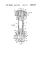
- FIG. 1 is a diagrammatic sectional view through a first embodiment of ER controlled device in accordance with the invention
- FIG. 2 is a composite end view of the device of FIG. 1;
- FIG. 3 is a sectional diagrammatic view, to a larger scale, of a modified portion of the embodiment of FIGS. 1 and 2;
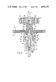
- FIGS. 4 to 8 are axial sectional views through five further embodiments of ER controlled devices.
- FIG. 1 it is assumed that an upper, input shaft 1, is driven in the direction indicated, the shaft 1 carrying an enlarged diameter housing 2, which forms one element of an ER clutch 3, the ER fluid being indicated at 4.
- the clutch 3 can be of any convenient form, but the example illustrated in FIG. 1 is a combination of plate and tubular forms, active on all surfaces.
- the clutch 3 has a driven element 5 connected to a short shaft 6, which is rotatable in bearings 7 and 8, in the housing 2.
- the bearings 7 and 8 must be sealed against the ER fluid 4 and, in practice, some means must be provided to take up any expansion of the ER fluid in the clutch.
- the shaft 6 is co-axial with the shaft 1, projects beyond the housing 2 and is rotatable in a third bearing 9, located in a housing 10 on the end of a lower, output shaft 11. From the shaft 6 projectss a radial arm 12, while a second radial arm 13 projects from the housing 10.
- the radial arms 12 and 13, carry respective axial extensions 14 and 15 which project, side by side, over the housing 2.
- a thin steel band 16, connects the axial extensions 14 and 15, passing around the housing 2.
- Frictional forces between the band 16 and the housing 2 amplify the torque due to the ER clutch 3, thus transmitting a magnified torque to the arm 13, and hence to the shaft 11.
- the torque output is a linear function of the torque input, and is therefore determined by the torque from the ER clutch 3.
- the degree of amplification is determined by the coefficient of friction between the band 16 and the housing 2. Taking a typical value of 0.2 for the friction coefficient, for a single turn around the housing 2 indicated in FIGS. 1 and 2, a torque amplification of 3.5 is achieved. If this is insufficient, two turns of the band 14 around the housing 2 will give a factor of 12, and three turns a factor of 43.
- a separate spring might be used, instead of relying on the inherent springy properties of the steel band 16. It may be found that the tensile strength of the steel band 16 which must be thin in order to bend around the housing 2, will be insufficient to transmit the torque. In such cases, the steel band 16 may be replaced by a jointed chain, similar to that of a tank track, and provided with wearing surfaces machined to the radius of the housing 2. To protect the ER fluid 4 from heat generated by friction of the band 16 on the housing 2, an outer rubbing ring could be fixed on the latter, spaced to allow air circulation.
- the device will only transmit rotation in one direction. If bi-directional operation is required, the modification shown in FIG. 3 can be used.
- the end of the arm 13 is bifurcated, and has two slots 17 through which ends 18 of the band 16 are passed; a ring 19 is attached to each end 18, which rings 19 are arranged to overlap, and the axial end of the arm 12 is passed through both. Displacement of the arm 12 in either direction pulls one end of the band 16 in the normal manner, but the main torque is transmitted to the arm 13 by one or other of the rings 19 abutting against a wall 20 of their slots 17 in the bifurcation of the arm 13.
- the simple arm 13 can be replaced by a more complex gear or lever linkage if required; the torque output could be further magnified thereby, although at the cost of increased friction and reduced frequency response.
- the natural frequency of the system which will be determined by the stiffness of the band 16 in tension, will be high.
- This device will therefore be capable of taking advantage of the high speed of response of ER fluids, once the original ⁇ threshold ⁇ level has been passed.
- the high voltage is preferably applied to the driven element 5, with the housing 2 assumed to be earthed.
- Such high voltage could be applied via a slip-ring on the shaft 6.
- the high voltage connection brings a disadvantage, in that it must be protected, and there must be a fixed element to hold the connection. This can be avoided, as indicated in the tubular and flat plate ER clutches of FIGS. 4 and 5, respectively, for example by winding many turns of fine wire around the periphery of the housing 2, but avoiding of course the region on which the band 16 is intended to operate.
- a primary and stationary coil 21 surrounds a secondary coil 22 wound onto the housing 2.
- piloted clutch unit of FIG. 4 is a standard oil-seal 31 to protect the bearing 9--with present fluids, the seal 31 must be ⁇ Viton ⁇ (Du Pont), since other elastomers are attacked by the fluid.
- a bush 32 of PTFE insulating material which has been found to be reliable in areas of high electrical stress in contact with ER fluid, with an inner 33 of epoxy resin.
- the bearings 8 and 10 are retained in a conventional manner by circlips located in grooves 34 and 35 respectively.
- the housing 2 is illustrated as carrying a press-fit sleeve 2A which is the portion of the housing engageable by the friction band 14.
- the device of the embodiment of FIGS. 5 is similar to FIG. 4, but adapted to use a flat-plate ER driven clutch element 5 to which is attached a metal sleeve 36 engaged by the ball 29, the sleeve 36 housing an epoxy resin cup 37 and, partially the PTFE bush 32, there being a single, angular contact ball bearing 8 protected by the seal 31, while bearing 9 is in this embodiment constituted by a cupped, nylon (trade mark) bush provided with a retaining screw 38.
- this flat-plate clutch could readily be adapted to a multi-plate form.
- FIGS. 6 and 7 illustrate embodiments of the invention in which the input or output is taken off by a belt pulley 39, (or a gear). It will be apparent that these layouts lead to very simple devices in which the high voltage connections can be easily made via a contact 40. These embodiments also illustrate a multi-wrap band 16A, and a lower insulator 32A.
- the housing 2 is shown provided with air holes 41, while the housing 10 is extended and enlarged to surround the housing 2, being supported on a bearing 8A on the input shaft 1, whilst being provided with air holes 42 and air scoops 43, to allow air circulation for cooling purposes, a cooling air space 44, a slip ring 45 with an electrical lead 46 passing through insulator 32B, although in this embodiment the ease of introduction of the high voltage signal is sacrificed thereby.
- FIG. 9 illustrates yet another embodiment of the basic invention, applied to a clutching device used to pull in a wire or cord 47.
- the latter is attached to a drum 48, which is part of an ER clutch 3.
- Application of a field to the ER clutch 3 tightens the cord 47 around a rod 49, which is continuously rotated with the driving member of the ER clutch, conveniently by a belt or gears (not shown) between the two.
- the tension generated by the ER clutch 3, which can be small, is therefore amplified by friction around the rod 49. It will be seen that this system lends itself to very small devices, which can be closely packed together if required; in this case, the clutch itself is conveniently in the form of a disc, with the voltage applied across gap 50.
Landscapes
- Engineering & Computer Science (AREA)
- General Engineering & Computer Science (AREA)
- Mechanical Engineering (AREA)
- Mechanical Operated Clutches (AREA)
- Hydraulic Clutches, Magnetic Clutches, Fluid Clutches, And Fluid Joints (AREA)
- Braking Arrangements (AREA)
- Retarders (AREA)
- Friction Gearing (AREA)
- Lubricants (AREA)
- Pulleys (AREA)
Applications Claiming Priority (2)
| Application Number | Priority Date | Filing Date | Title |
|---|---|---|---|
| GB8423691 | 1984-09-19 | ||
| GB848423691A GB8423691D0 (en) | 1984-09-19 | 1984-09-19 | Servo-operated torque controlling devices |
Publications (1)
| Publication Number | Publication Date |
|---|---|
| US4664236A true US4664236A (en) | 1987-05-12 |
Family
ID=10566950
Family Applications (1)
| Application Number | Title | Priority Date | Filing Date |
|---|---|---|---|
| US06/774,972 Expired - Fee Related US4664236A (en) | 1984-09-19 | 1985-09-11 | Electrically controlled, progressive, frictional, torque transmitting device |
Country Status (6)
| Country | Link |
|---|---|
| US (1) | US4664236A (de) |
| EP (1) | EP0178078B1 (de) |
| JP (1) | JPH0786373B2 (de) |
| AT (1) | ATE36283T1 (de) |
| DE (1) | DE3564225D1 (de) |
| GB (1) | GB8423691D0 (de) |
Cited By (17)
| Publication number | Priority date | Publication date | Assignee | Title |
|---|---|---|---|---|
| US4815674A (en) * | 1987-12-21 | 1989-03-28 | General Motors Corporation | Retractor with electro-rheological lock |
| US4896754A (en) * | 1988-08-25 | 1990-01-30 | Lord Corporation | Electrorheological fluid force transmission and conversion device |
| US4941782A (en) * | 1988-12-30 | 1990-07-17 | Gte Valenite Corporation | Adjustable boring bar |
| US5007303A (en) * | 1988-04-13 | 1991-04-16 | Nissan Motor Co., Ltd. | Variable inertial mass flywheel |
| US5090531A (en) * | 1990-01-10 | 1992-02-25 | Lord Corporation | Electrophoretic fluid differential |
| US5524743A (en) * | 1991-01-24 | 1996-06-11 | British Technology Group Ltd. | Quick-acting drive devices |
| GB2300697A (en) * | 1995-05-10 | 1996-11-13 | Gareth John Monkman | Electrorheological torque transmission |
| US5598908A (en) * | 1995-06-05 | 1997-02-04 | Gse, Inc. | Magnetorheological fluid coupling device and torque load simulator system |
| US5823309A (en) * | 1997-05-23 | 1998-10-20 | General Motors Corporation | Magnetorheological transmission clutch |
| US5845752A (en) * | 1997-06-02 | 1998-12-08 | General Motors Corporation | Magnetorheological fluid clutch with minimized reluctance |
| US5848678A (en) * | 1997-06-04 | 1998-12-15 | General Motors Corporation | Passive magnetorheological clutch |
| US5967274A (en) * | 1997-10-21 | 1999-10-19 | Dana Corporation | Wrap spring clutch/brake assembly having soft start and soft stop capabilities |
| US20050092570A1 (en) * | 2003-11-03 | 2005-05-05 | China Patent Investment Limited | Electrorheological clutch |
| US20090266666A1 (en) * | 2008-04-29 | 2009-10-29 | Mcdaniel Andrew Joseph | Magneto-rheological clutch and wheel transmission apparatuses and methods |
| US20090266670A1 (en) * | 2008-04-29 | 2009-10-29 | Mcdaniel Andrew Joseph | Magneto-rheological brake-clutch apparatuses and methods |
| US8127907B1 (en) | 2009-02-03 | 2012-03-06 | White Brian R | Marine transmission using rheological fluids |
| US10099776B2 (en) * | 2015-03-27 | 2018-10-16 | Hamilton Sundstrand Corporation | Rheologic fluid coupler for redundant linear electromechanical actuators |
Families Citing this family (5)
| Publication number | Priority date | Publication date | Assignee | Title |
|---|---|---|---|---|
| GB9101577D0 (en) * | 1991-01-24 | 1991-03-06 | Nat Res Dev | Quick-acting drive devices |
| DE4142634C1 (de) * | 1991-12-21 | 1993-03-25 | Heraeus Instruments Gmbh, 6450 Hanau, De | |
| DE4324451A1 (de) * | 1993-07-21 | 1995-01-26 | Zahnradfabrik Friedrichshafen | Vorrichtung zur Übertragung/Absorption eines Drehmomentes |
| US6837919B2 (en) | 1994-05-04 | 2005-01-04 | Nippon Shokubai Co., Ltd. | Method for deaerating electrorheological fluid in a closed device |
| DE112007002631A5 (de) | 2006-11-03 | 2009-10-01 | Magna Powertrain Ag & Co Kg | Momentübertragungseinheit |
Citations (3)
| Publication number | Priority date | Publication date | Assignee | Title |
|---|---|---|---|---|
| US2523772A (en) * | 1947-10-08 | 1950-09-26 | Comm Engineering Pty Ltd | Electromagnetically operated coil clutch |
| US4201281A (en) * | 1978-05-22 | 1980-05-06 | Warner Electric Brake & Clutch Company | Electromagnetic clutch having a contractible friction shoe |
| US4444298A (en) * | 1981-07-10 | 1984-04-24 | The Secretary Of State For Defence In Her Britannic Majesty's Government Of The United Kingdom Of Great Britain And Northern Ireland | Viscous shear clutch |
Family Cites Families (7)
| Publication number | Priority date | Publication date | Assignee | Title |
|---|---|---|---|---|
| US3618730A (en) * | 1969-12-12 | 1971-11-09 | Vari Typer Corp | Torque-limiting clutch |
| FR2344748A1 (fr) * | 1976-03-19 | 1977-10-14 | Verdol Sa | Dispositif d'embrayage, notamment pour la commande de l'entrainement des bobines envideuses sur machines textiles |
| FR2351324A1 (fr) * | 1976-05-10 | 1977-12-09 | Sulzer Ag | Coupleur electromagnetique a engrenages |
| JPS5335355U (de) * | 1976-09-02 | 1978-03-28 | ||
| JPS57190155A (en) * | 1981-05-14 | 1982-11-22 | Mitsubishi Electric Corp | Power transmission device |
| JPS57205466A (en) * | 1981-06-12 | 1982-12-16 | Matsushita Electric Ind Co Ltd | Magnetic ink for recording |
| EP0099214B1 (de) * | 1982-07-05 | 1988-11-09 | Mitsubishi Denki Kabushiki Kaisha | Elektromagnetische Kupplung |
-
1984
- 1984-09-19 GB GB848423691A patent/GB8423691D0/en active Pending
-
1985
- 1985-09-11 US US06/774,972 patent/US4664236A/en not_active Expired - Fee Related
- 1985-09-12 EP EP85306474A patent/EP0178078B1/de not_active Expired
- 1985-09-12 DE DE8585306474T patent/DE3564225D1/de not_active Expired
- 1985-09-12 AT AT85306474T patent/ATE36283T1/de not_active IP Right Cessation
- 1985-09-19 JP JP60205474A patent/JPH0786373B2/ja not_active Expired - Lifetime
Patent Citations (3)
| Publication number | Priority date | Publication date | Assignee | Title |
|---|---|---|---|---|
| US2523772A (en) * | 1947-10-08 | 1950-09-26 | Comm Engineering Pty Ltd | Electromagnetically operated coil clutch |
| US4201281A (en) * | 1978-05-22 | 1980-05-06 | Warner Electric Brake & Clutch Company | Electromagnetic clutch having a contractible friction shoe |
| US4444298A (en) * | 1981-07-10 | 1984-04-24 | The Secretary Of State For Defence In Her Britannic Majesty's Government Of The United Kingdom Of Great Britain And Northern Ireland | Viscous shear clutch |
Cited By (21)
| Publication number | Priority date | Publication date | Assignee | Title |
|---|---|---|---|---|
| US4815674A (en) * | 1987-12-21 | 1989-03-28 | General Motors Corporation | Retractor with electro-rheological lock |
| US5007303A (en) * | 1988-04-13 | 1991-04-16 | Nissan Motor Co., Ltd. | Variable inertial mass flywheel |
| US4896754A (en) * | 1988-08-25 | 1990-01-30 | Lord Corporation | Electrorheological fluid force transmission and conversion device |
| US4941782A (en) * | 1988-12-30 | 1990-07-17 | Gte Valenite Corporation | Adjustable boring bar |
| US5090531A (en) * | 1990-01-10 | 1992-02-25 | Lord Corporation | Electrophoretic fluid differential |
| US5524743A (en) * | 1991-01-24 | 1996-06-11 | British Technology Group Ltd. | Quick-acting drive devices |
| GB2300697B (en) * | 1995-05-10 | 1999-06-16 | Gareth John Monkman | Electrorheological torque transmission |
| GB2300697A (en) * | 1995-05-10 | 1996-11-13 | Gareth John Monkman | Electrorheological torque transmission |
| US5598908A (en) * | 1995-06-05 | 1997-02-04 | Gse, Inc. | Magnetorheological fluid coupling device and torque load simulator system |
| US5823309A (en) * | 1997-05-23 | 1998-10-20 | General Motors Corporation | Magnetorheological transmission clutch |
| US5845752A (en) * | 1997-06-02 | 1998-12-08 | General Motors Corporation | Magnetorheological fluid clutch with minimized reluctance |
| US5848678A (en) * | 1997-06-04 | 1998-12-15 | General Motors Corporation | Passive magnetorheological clutch |
| US5967274A (en) * | 1997-10-21 | 1999-10-19 | Dana Corporation | Wrap spring clutch/brake assembly having soft start and soft stop capabilities |
| US20050092570A1 (en) * | 2003-11-03 | 2005-05-05 | China Patent Investment Limited | Electrorheological clutch |
| US6942081B2 (en) | 2003-11-03 | 2005-09-13 | China Patent Investment Limited | Electrorheological clutch |
| US20090266666A1 (en) * | 2008-04-29 | 2009-10-29 | Mcdaniel Andrew Joseph | Magneto-rheological clutch and wheel transmission apparatuses and methods |
| US20090266670A1 (en) * | 2008-04-29 | 2009-10-29 | Mcdaniel Andrew Joseph | Magneto-rheological brake-clutch apparatuses and methods |
| US7891474B2 (en) | 2008-04-29 | 2011-02-22 | Honda Motor Co., Ltd. | Magneto-rheological brake-clutch apparatuses and methods |
| US8016092B2 (en) | 2008-04-29 | 2011-09-13 | Honda Motor Co., Ltd. | Magneto-rheological clutch and wheel transmission apparatuses and methods |
| US8127907B1 (en) | 2009-02-03 | 2012-03-06 | White Brian R | Marine transmission using rheological fluids |
| US10099776B2 (en) * | 2015-03-27 | 2018-10-16 | Hamilton Sundstrand Corporation | Rheologic fluid coupler for redundant linear electromechanical actuators |
Also Published As
| Publication number | Publication date |
|---|---|
| JPS6192327A (ja) | 1986-05-10 |
| DE3564225D1 (en) | 1988-09-15 |
| EP0178078B1 (de) | 1988-08-10 |
| EP0178078A1 (de) | 1986-04-16 |
| ATE36283T1 (de) | 1988-08-15 |
| GB8423691D0 (en) | 1984-10-24 |
| JPH0786373B2 (ja) | 1995-09-20 |
Similar Documents
| Publication | Publication Date | Title |
|---|---|---|
| EP0178078B1 (de) | Elektrisch gesteuerte progressive Reibungsvorrichtung zur Drehmomentübertragung | |
| JP5425269B2 (ja) | 磁界応答材料を有するブレーキ | |
| EP0909901B1 (de) | Magnetorheologische Flüssigkeitskupplung | |
| CA1315839C (en) | Er fluid force transmission and conversion device with magnetic coupling | |
| US2575360A (en) | Magnetic fluid torque and force transmitting device | |
| JP2002501591A (ja) | 磁気粒子ダンパ装置 | |
| US8490769B2 (en) | Lever applied solenoid clutch actuator | |
| US5133437A (en) | Wrap spring clutch with brake | |
| EP0099214B1 (de) | Elektromagnetische Kupplung | |
| US6209698B1 (en) | Speed control wrap spring clutch | |
| EP1201954A2 (de) | Leichtgewichtige Magnetpartikel-Kupplung | |
| US6047805A (en) | Electric clutch and brake | |
| US3176809A (en) | Particulate magnetic material clutch with friction brake | |
| US3308410A (en) | Rotary actuator having associated clutch means | |
| WO2005124177A1 (en) | Rotary fluid coupling | |
| US3197003A (en) | Temperature-responsive clutch or brake | |
| US4630722A (en) | Electromagnetic wrap spring clutch | |
| US3469665A (en) | Electromagnetic connector | |
| US3394783A (en) | Magnetic fluid coupling | |
| US3048046A (en) | Power transmission for variable speed and torque | |
| US2809731A (en) | Magnetic particle coupling device with nickel-coated iron particles | |
| US3272290A (en) | Electromagnetic device | |
| US2897931A (en) | Clutch with magnetic powder mixture for force transmitting devices | |
| US7516826B2 (en) | Electro-slip clutch | |
| US2885045A (en) | Power transmission |
Legal Events
| Date | Code | Title | Description |
|---|---|---|---|
| AS | Assignment |
Owner name: ER FLUID DEVELOPMENTS LIMITED, 34 GREENFIELD ROAD, Free format text: ASSIGNMENT OF ASSIGNORS INTEREST.;ASSIGNOR:STANGROOM, JAMES E.;REEL/FRAME:004496/0457 Effective date: 19860110 |
|
| FEPP | Fee payment procedure |
Free format text: PAYOR NUMBER ASSIGNED (ORIGINAL EVENT CODE: ASPN); ENTITY STATUS OF PATENT OWNER: SMALL ENTITY |
|
| FPAY | Fee payment |
Year of fee payment: 4 |
|
| FPAY | Fee payment |
Year of fee payment: 8 |
|
| REMI | Maintenance fee reminder mailed | ||
| LAPS | Lapse for failure to pay maintenance fees | ||
| FP | Lapsed due to failure to pay maintenance fee |
Effective date: 19990512 |
|
| STCH | Information on status: patent discontinuation |
Free format text: PATENT EXPIRED DUE TO NONPAYMENT OF MAINTENANCE FEES UNDER 37 CFR 1.362 |