US4664591A - Apparatus for placing electronic and/or electrical components on a substrate - Google Patents
Apparatus for placing electronic and/or electrical components on a substrate Download PDFInfo
- Publication number
- US4664591A US4664591A US06/799,523 US79952385A US4664591A US 4664591 A US4664591 A US 4664591A US 79952385 A US79952385 A US 79952385A US 4664591 A US4664591 A US 4664591A
- Authority
- US
- United States
- Prior art keywords
- pick
- carriage
- supporting beam
- devices
- platforms
- Prior art date
- Legal status (The legal status is an assumption and is not a legal conclusion. Google has not performed a legal analysis and makes no representation as to the accuracy of the status listed.)
- Expired - Fee Related
Links
- 239000000758 substrate Substances 0.000 title claims abstract description 18
- 230000005540 biological transmission Effects 0.000 claims abstract description 6
- 210000001331 nose Anatomy 0.000 description 3
- 238000010276 construction Methods 0.000 description 2
- 230000001105 regulatory effect Effects 0.000 description 2
- 210000005069 ears Anatomy 0.000 description 1
Images


Classifications
-
- H—ELECTRICITY
- H05—ELECTRIC TECHNIQUES NOT OTHERWISE PROVIDED FOR
- H05K—PRINTED CIRCUITS; CASINGS OR CONSTRUCTIONAL DETAILS OF ELECTRIC APPARATUS; MANUFACTURE OF ASSEMBLAGES OF ELECTRICAL COMPONENTS
- H05K13/00—Apparatus or processes specially adapted for manufacturing or adjusting assemblages of electric components
- H05K13/04—Mounting of components, e.g. of leadless components
- H05K13/0404—Pick-and-place heads or apparatus, e.g. with jaws
- H05K13/0408—Incorporating a pick-up tool
-
- H—ELECTRICITY
- H05—ELECTRIC TECHNIQUES NOT OTHERWISE PROVIDED FOR
- H05K—PRINTED CIRCUITS; CASINGS OR CONSTRUCTIONAL DETAILS OF ELECTRIC APPARATUS; MANUFACTURE OF ASSEMBLAGES OF ELECTRICAL COMPONENTS
- H05K13/00—Apparatus or processes specially adapted for manufacturing or adjusting assemblages of electric components
- H05K13/04—Mounting of components, e.g. of leadless components
- H05K13/0404—Pick-and-place heads or apparatus, e.g. with jaws
-
- Y—GENERAL TAGGING OF NEW TECHNOLOGICAL DEVELOPMENTS; GENERAL TAGGING OF CROSS-SECTIONAL TECHNOLOGIES SPANNING OVER SEVERAL SECTIONS OF THE IPC; TECHNICAL SUBJECTS COVERED BY FORMER USPC CROSS-REFERENCE ART COLLECTIONS [XRACs] AND DIGESTS
- Y10—TECHNICAL SUBJECTS COVERED BY FORMER USPC
- Y10T—TECHNICAL SUBJECTS COVERED BY FORMER US CLASSIFICATION
- Y10T29/00—Metal working
- Y10T29/49—Method of mechanical manufacture
- Y10T29/49002—Electrical device making
- Y10T29/49117—Conductor or circuit manufacturing
- Y10T29/49124—On flat or curved insulated base, e.g., printed circuit, etc.
- Y10T29/4913—Assembling to base an electrical component, e.g., capacitor, etc.
- Y10T29/49133—Assembling to base an electrical component, e.g., capacitor, etc. with component orienting
Definitions
- the invention relates to an apparatus for placing electronic and/or electrical components on a substrate, which apparatus comprises a first carriage which is movable in an X direction and on which a second carriage is guided for a movement in a Y direction at right angles to the X direction, this second carriage carrying a number of pick-up devices each capable of picking up a component.
- This known apparatus is less suitable for components whose form and size deviate from the so-called chip like components.
- the invention has for its object to provide an apparatus by which larger components can be picked up from the supply positions and can then be placed on a substrate.
- the apparatus according to the invention is characterized in that a first supporting beam fixedly secured to the Y carriage is provided with a number of rotable platforms, each of which is coupled by a transmission with a common drive for a rotary movement and is provided with an operable locking mechanism by which a pick-up device can be locked to each of the platforms, the Y carriage further comprising a second supporting beam which can be moved along a guide arranged at right angles to the X-Y plane and comprises a number of recessed parts, each of which is adapted to receive a pick-up device which can be locked therein in a manner such that each of the pick-up devices can be arbitrarily locked to its associated platform or to the associated recessed part.
- the pick-up devices are preferably constructed as grippers with at least a pair of jaws by which a component can be picked up.
- the carriages Upon starting, the carriages are first moved so that the platforms connected to the Y carriage are situated above the supply positions of the components.
- the second supporting beam is located in its upper position, in which the pick-up devices are in contact with their associated platforms and the pick-up devices are each enclosed by their associated recessed parts of the second supporting beam.
- each of the pick-up devices is brought in order of succession above the position in which it is to be placed.
- the relevant pick-up device is disengaged from its platform and is locked to the respective recessed part of the second supporting beam. Subsequently, this beam moves downwards and places the component on the substrate, after which the grippers are operated so that the component is released.
- the pick-up devices are operated pneumatically, and, in order to avoid the use of supply hoses, each of said recessed parts is provided with a number of ducts which can be connected to a source of compressed air and which open out of the inner side of the recessed part and can cooperate there with ducts in the associated pick-up device.
- each pick-up device is provided with a central part which carries at least one pair of gripper jaws which are movable towards and away from each other, this central part being enclosed by a housing and being provided with a flange arranged at right angles to the centre line and disposed between an edge of the housing and a pressure member subjected to spring pressure, and ducts being provided in the housing through which air under pressure canbe introduced between the two sides of the flange and the edge of the housing and the pressure member, respectively.
- each of the platforms may be provided with a pin which is pivotably connected to a common part which is connected through a driving rod mechanism to the shaft of an electric motor.
- the control of the drives of the three carriages, of the motor for the rotary movement and of the pneumatic operation of the pick-up devices can be effected by means of a suitable program.
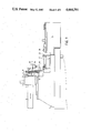
- FIG. 1 shows diagrammatically in side elevation an apparatus for placing components on a substrate
- FIG. 2 shows the apparatus of FIG. 1 in plan view
- FIG. 3 shows in perspective view on an enlarged scale the part of the apparatus shown in FIGS. 1 and 2 which carries the pick-up devices for the components;
- FIG. 4 shows a part of FIG. 3 in a sectional view
- FIG. 5 shows a part of FIG. 3 in plan view
- FIG. 6 is a sectional view taken on the line VI--VI in FIG. 5;
- FIG. 7 is a sectional view of a holder for receiving a pick-up device for a component
- FIG. 8 is a sectional view of a holder in which is arranged a pick-up device, which is not rigidly coupled to the holder during the step of gripping a component.
- the base part of the apparatus is designated by reference numeral 1.
- a frame 2 On this base part is arranged a frame 2, in which are located guides and a drive for an X carriage 3.
- a motor 4 On the frame 2 is mounted a motor 4 which can drive the carriage 3.
- a guide beam 5 On the end face of the carriage 3 is mounted.
- a motor 7 (FIG. 2) with transmission means can move the Y carriage 6 along the guide beam 5.
- the Y carriage 6 has fixedly connected to it a first supporting beam 10, which is provided with a number of rotable platforms 12, to each of which a pick-up device 14 can be connected.
- the Y carriage is further provided with guides 16 along which a second supporting beam 18 can move in the Z direction.
- Substrates 22 can be supplyed and positioned below the beam 18 by means of the transport device 20.
- a device 24 for supplying components is arranged apposite the beams 10 and 18.
- This device which is shown only diagrammatically in the drawing, comprises a number of tracks 26 (FIG. 2), along which the various components are supplied to supply positions 28.
- the beam 10 is fixedly connected to a plate 30, which is provided on its rear side with means (not shown) by which it is secured to the Y carriage 6.
- an electric motor 32 On the beam 10 is arranged an electric motor 32, on whose shaft is fixed a collar 34, which is provided with an eccentrically arranged pin 36.
- the pin 36 is rotatably journalled in a connection yoke 38.
- the yoke 38 is rotatably connected by four pins 40 to collars 42, which are each secured on an associated shaft 44. Two of the collars 42 are coupled to each other through a toothed belt 46.
- the shafts 44 are rotatably journalled in the beam 10 and each carries on its lower end a rotatable platform 12.
- a switching plate 50 (FIG. 5) is arranged so as to be rotatable about each of the bearings of the rotatable platforms 12.
- Each switching plate 50 carries three pins 52, and a clamping member 54 is secured so as to be rotatable about each of these pins.
- Each clamping member is provided with a slot 56, in which a pin 58 rigidly connected to the beam 10 is slidably arranged.
- Each clamping member 54 is provided with a nose portion 60 (FIG. 6) having a thickness such that it can engage in a groove 62 in the respective holder 14 (FIG. 4).
- Each of the switching plates 50 is further connected through a gudgeon-pin connection 64 (FIGS. 5 and 6) to a piston rod 66 (FIG. 6) of a double-acting pneumatic motor 68.
- Each of the holders 14 is adapted to receive a pick-up device, which is composed of a base portion 72 (FIG. 3) having a number of pneumatically operable members, of which only two securing parts 74 are shown, which can be moved pneumatically away from each other and towards each other. To these two parts 74 are connected a pair of gripper jaws 76 which have a form adapted to the component to be picked up.
- the holders 14 each have a cylindrical wall 78, which is provided at suitable areas with bores 80, which are arranged so that they communicate on the inner side of the cylinder 78 with ducts in the base portion 72 of the pick-up devices for the supply of compressed air to the various members therein.
- the cylinders 78 are each provided at the upper side with a plate 82, which is provided with a central pin 84 adapted to cooperate with a central receiving aperture 86 (FIG. 3) in the respective platform 12 and a catch pin 88 adapted to cooperate with a catch hole 90 in the respective platform 12.
- the plate 82 is further provided with the aforementioned groove 62.
- the beam 18 (FIG. 3) can move in the Z direction along guides and carries a number of cylinders 100, which are each provided on the inner side with a number of grooves 102 accommodating O-rings 104 (FIG. 7) and with a number of further grooves 106.
- the grooves 102 all communicate with a common duct 108 for the supply of compressed air.
- the grooves 106 each have an individual duct 110 for the supply of compressed air, all ducts for the supply of compressed air at each holder being connected to a regulating device (not shown), by means of which according to a program compressed air can arbitrarily be supplied to the common duct 108 or to one or more of the ducts 110.
- a ring 112 (FIG. 3) is arranged to rotate about each of the cylinders 100 and is provided with ears 114 with holes 116 adapted to cooperate with the pins 52.
- FIG. 8 shows a holder provided with the said cylindrical wall 78 comprising a pick-up device (shown diagrammatically) which is provided with a flange 120.
- the flange 120 is arranged between an edge 121 of the holder and a movable pressure member 122, which is urged towards the flange by one or more springs 123.
- the desired components are brought into their supply positions 28.
- the assembly of beams 10 and 18 is brought above the supply positions 28.
- the beam 18 now receives the pick-up devices 14 in the cylinders 100. This is effected by the pneumatic motors 68 rotating the switching plates 50 of all the pick-up devices so that the noses 60 leave the grooves 62. Furthermore, compressed air is supplied to the ducts 108, as a result of which the O rings in the grooves 102 are forced against the cylinders 78. As a result, the pick-up cylinders 78 are fixedly connected to the beam 18.
- the beam 18 with the pick-up devices 14 fixed therein is now moved to the supply positions 28, after which, by the supply of compressed air to the required ducts 110 and the openings 80, the gripper jaws 76 are opened so that they can pick up a component, whereupon they are closed again.
- the beam 18 is then moved upwards again until the pick-up devices 14 again engage the switching plates 12. Subsequently, the assembly of beams 10 and 18 is brought above the substrate 22 and the operation of placing the picked-up components on this substrate can begin.
- the desired pick-up devices 14 are clamped in their cylinders 100 by means of compressed air in the duct 108 and the grooves 102.
- the lock between the relevant pick-up devices 14 and their associated platforms 12 is released. This is effected by the relevant pneumatic motors 68 being operated so that the associated switching plates 50 are rotated in the direction in which the noses 60 leave the grooves 62.
- the pick-up devices 14 are now fixedly connected to the beam 18 and can be moved therewith towards the substrate, while a program ensures that the relevant components are brought above their correct positions by the X and Y carriages 3 and 5, respectively.
- the operation of placing is again controlled pneumatically, while compressed air is supplied by a regulating valve to the ducts 110 in the correct order of succession, by means of which through openings 80 the various members of the gripper jaws 76 are operated.
- an apparatus is obtained by means of which components of different dimensions and shape can be placed on substrates at a high speed and with a great accuracy.
Landscapes
- Engineering & Computer Science (AREA)
- Manufacturing & Machinery (AREA)
- Microelectronics & Electronic Packaging (AREA)
- Specific Conveyance Elements (AREA)
- Manipulator (AREA)
- Automatic Assembly (AREA)
- Machine Tool Units (AREA)
Applications Claiming Priority (2)
| Application Number | Priority Date | Filing Date | Title |
|---|---|---|---|
| NL8403513A NL8403513A (nl) | 1984-11-19 | 1984-11-19 | Inrichting voor het plaatsen van electronische en/of electrische onderdelen op een substraat. |
| NL8403513 | 1984-11-19 |
Publications (1)
| Publication Number | Publication Date |
|---|---|
| US4664591A true US4664591A (en) | 1987-05-12 |
Family
ID=19844786
Family Applications (1)
| Application Number | Title | Priority Date | Filing Date |
|---|---|---|---|
| US06/799,523 Expired - Fee Related US4664591A (en) | 1984-11-19 | 1985-11-19 | Apparatus for placing electronic and/or electrical components on a substrate |
Country Status (8)
| Country | Link |
|---|---|
| US (1) | US4664591A (de) |
| EP (1) | EP0183301B1 (de) |
| JP (1) | JPS61125743A (de) |
| KR (1) | KR920007125B1 (de) |
| CA (1) | CA1243128A (de) |
| DE (1) | DE3571546D1 (de) |
| NL (1) | NL8403513A (de) |
| SG (1) | SG85590G (de) |
Cited By (7)
| Publication number | Priority date | Publication date | Assignee | Title |
|---|---|---|---|---|
| US5058263A (en) * | 1989-12-21 | 1991-10-22 | U.S. Philips Corporation | Manipulation device |
| US5531556A (en) * | 1993-07-30 | 1996-07-02 | Sony Corporation | Rearrangement apparatus for manufacturing system |
| US20020196401A1 (en) * | 2001-06-25 | 2002-12-26 | Grace Anthony J. | Hybrid display device |
| US6727970B2 (en) | 2001-06-25 | 2004-04-27 | Avery Dennison Corporation | Method of making a hybrid display device having a rigid substrate and a flexible substrate |
| USRE41694E1 (en) | 2002-06-14 | 2010-09-14 | Xiao-Ming He | Method for roll-to-roll deposition of optically transparent and high conductivity metallic thin films |
| US20110220102A1 (en) * | 2002-12-17 | 2011-09-15 | Breathablebaby, Llc | Crib shield system and other breathable apparatus |
| US20180255671A1 (en) * | 2017-03-06 | 2018-09-06 | Panasonic Intellectual Property Management Co., Ltd. | Component mounting device and method of mounting component |
Families Citing this family (4)
| Publication number | Priority date | Publication date | Assignee | Title |
|---|---|---|---|---|
| GB2201940A (en) * | 1987-03-11 | 1988-09-14 | Philips Nv | Gripping device |
| GB2202821A (en) * | 1987-03-30 | 1988-10-05 | Philips Nv | Gripping device |
| GB2203121A (en) * | 1987-04-06 | 1988-10-12 | Philips Nv | Gripping device |
| KR102390758B1 (ko) * | 2016-09-29 | 2022-04-26 | 아셈블레온 비.브이. | 부품 배치 장치 및 부품 배치 장치 구동 방법 |
Citations (2)
| Publication number | Priority date | Publication date | Assignee | Title |
|---|---|---|---|---|
| US4154350A (en) * | 1976-10-15 | 1979-05-15 | Bell Maschinenfabrik Ag | Device for transporting hollow plastic blow moldings |
| US4475863A (en) * | 1982-05-24 | 1984-10-09 | Blatt Leland F | Electric servo drive lift unit |
Family Cites Families (1)
| Publication number | Priority date | Publication date | Assignee | Title |
|---|---|---|---|---|
| NL8201653A (nl) * | 1982-04-21 | 1983-11-16 | Philips Nv | Werkwijze en inrichting voor het plaatsen van chipvormige electrische en/of electronische onderdelen op een substraat. |
-
1984
- 1984-11-19 NL NL8403513A patent/NL8403513A/nl not_active Application Discontinuation
-
1985
- 1985-11-08 EP EP85201813A patent/EP0183301B1/de not_active Expired
- 1985-11-08 DE DE8585201813T patent/DE3571546D1/de not_active Expired
- 1985-11-14 CA CA000495374A patent/CA1243128A/en not_active Expired
- 1985-11-16 KR KR1019850008581A patent/KR920007125B1/ko not_active Expired
- 1985-11-16 JP JP60257514A patent/JPS61125743A/ja active Pending
- 1985-11-19 US US06/799,523 patent/US4664591A/en not_active Expired - Fee Related
-
1990
- 1990-10-24 SG SG855/90A patent/SG85590G/en unknown
Patent Citations (2)
| Publication number | Priority date | Publication date | Assignee | Title |
|---|---|---|---|---|
| US4154350A (en) * | 1976-10-15 | 1979-05-15 | Bell Maschinenfabrik Ag | Device for transporting hollow plastic blow moldings |
| US4475863A (en) * | 1982-05-24 | 1984-10-09 | Blatt Leland F | Electric servo drive lift unit |
Cited By (9)
| Publication number | Priority date | Publication date | Assignee | Title |
|---|---|---|---|---|
| US5058263A (en) * | 1989-12-21 | 1991-10-22 | U.S. Philips Corporation | Manipulation device |
| US5531556A (en) * | 1993-07-30 | 1996-07-02 | Sony Corporation | Rearrangement apparatus for manufacturing system |
| US20020196401A1 (en) * | 2001-06-25 | 2002-12-26 | Grace Anthony J. | Hybrid display device |
| US6727970B2 (en) | 2001-06-25 | 2004-04-27 | Avery Dennison Corporation | Method of making a hybrid display device having a rigid substrate and a flexible substrate |
| US6856086B2 (en) | 2001-06-25 | 2005-02-15 | Avery Dennison Corporation | Hybrid display device |
| USRE41694E1 (en) | 2002-06-14 | 2010-09-14 | Xiao-Ming He | Method for roll-to-roll deposition of optically transparent and high conductivity metallic thin films |
| US20110220102A1 (en) * | 2002-12-17 | 2011-09-15 | Breathablebaby, Llc | Crib shield system and other breathable apparatus |
| US20180255671A1 (en) * | 2017-03-06 | 2018-09-06 | Panasonic Intellectual Property Management Co., Ltd. | Component mounting device and method of mounting component |
| US11202374B2 (en) * | 2017-03-06 | 2021-12-14 | Panasonic Intellectual Property Management Co., Ltd. | Method of mounting component |
Also Published As
| Publication number | Publication date |
|---|---|
| CA1243128A (en) | 1988-10-11 |
| KR920007125B1 (ko) | 1992-08-24 |
| SG85590G (en) | 1991-01-04 |
| DE3571546D1 (en) | 1989-08-17 |
| EP0183301A1 (de) | 1986-06-04 |
| NL8403513A (nl) | 1986-06-16 |
| EP0183301B1 (de) | 1989-07-12 |
| JPS61125743A (ja) | 1986-06-13 |
| KR860004568A (ko) | 1986-06-23 |
Similar Documents
| Publication | Publication Date | Title |
|---|---|---|
| US4664591A (en) | Apparatus for placing electronic and/or electrical components on a substrate | |
| US4987676A (en) | End effector for a robotic system | |
| EP0253162A3 (de) | Vorrichtung und Verfahren zum Transferieren von Werkstücken | |
| JPH0823194A (ja) | 電子部品表面実装装置 | |
| CN217096570U (zh) | 一种全自动多工位钻攻设备 | |
| US4678393A (en) | Loading and unloading mechanism | |
| US4930976A (en) | Multiple gripper turret for part handling devices and method of handling parts | |
| US5081763A (en) | Automated drilling station | |
| JPS6216818A (ja) | 折りたたみ作業における金属板自動操作方法および装置 | |
| US5056844A (en) | Multiple jaw centering head structure for surface mounted component placement machines | |
| US5106138A (en) | Linear tweezers | |
| US6137286A (en) | Test handler | |
| US20070131733A1 (en) | Apparatus and method for arranging devices for processing | |
| US4917568A (en) | Suction pick-up apparatus for electrical or electronic components | |
| KR100377128B1 (ko) | 개인휴대통신기 다운로드 시스템 | |
| CN100410014C (zh) | 机械加工设备 | |
| CN113120576B (zh) | 高速旋转式物料取放装置 | |
| US10766073B2 (en) | Component mounting apparatus and component mounting method | |
| JPS61110500A (ja) | 自動実装装置および方法 | |
| CN219525480U (zh) | 通讯端子装配用自动化换向上料设备 | |
| CN218612366U (zh) | 激光自动焊接机杯身传送带装置 | |
| CN114585478B (zh) | 处理系统 | |
| KR0152883B1 (ko) | 표면실장기 헤드툴의 부품정렬장치 | |
| KR100535727B1 (ko) | 노즐 셋팅 장치 및 그 방법 | |
| CN120861895A (zh) | 一种阀体六面自动铣削加工设备 |
Legal Events
| Date | Code | Title | Description |
|---|---|---|---|
| AS | Assignment |
Owner name: U.S. PHILIPS CORPORATION, 100 EAST 42ND STREET, NE Free format text: ASSIGNMENT OF ASSIGNORS INTEREST.;ASSIGNORS:FAES, FRANCISCUS C.M.;VAN DE VEN, JOHANNES T.A.;VERBERNE, PETRUS A.C.;AND OTHERS;REEL/FRAME:004630/0231;SIGNING DATES FROM 19860110 TO 19861001 Owner name: U.S. PHILIPS CORPORATION, A CORP OF DE,NEW YORK Free format text: ASSIGNMENT OF ASSIGNORS INTEREST;ASSIGNORS:FAES, FRANCISCUS C.M.;VAN DE VEN, JOHANNES T.A.;VERBERNE, PETRUS A.C.;AND OTHERS;SIGNING DATES FROM 19860110 TO 19861001;REEL/FRAME:004630/0231 |
|
| FEPP | Fee payment procedure |
Free format text: PAYOR NUMBER ASSIGNED (ORIGINAL EVENT CODE: ASPN); ENTITY STATUS OF PATENT OWNER: LARGE ENTITY |
|
| FPAY | Fee payment |
Year of fee payment: 4 |
|
| REMI | Maintenance fee reminder mailed | ||
| LAPS | Lapse for failure to pay maintenance fees | ||
| FP | Lapsed due to failure to pay maintenance fee |
Effective date: 19950517 |
|
| STCH | Information on status: patent discontinuation |
Free format text: PATENT EXPIRED DUE TO NONPAYMENT OF MAINTENANCE FEES UNDER 37 CFR 1.362 |