US4687176A - Flow control valve for a flexible walled tube - Google Patents
Flow control valve for a flexible walled tube Download PDFInfo
- Publication number
- US4687176A US4687176A US06/882,840 US88284086A US4687176A US 4687176 A US4687176 A US 4687176A US 88284086 A US88284086 A US 88284086A US 4687176 A US4687176 A US 4687176A
- Authority
- US
- United States
- Prior art keywords
- section
- control valve
- flow control
- tubular member
- inner tubular
- Prior art date
- Legal status (The legal status is an assumption and is not a legal conclusion. Google has not performed a legal analysis and makes no representation as to the accuracy of the status listed.)
- Expired - Fee Related
Links
Images
Classifications
-
- A—HUMAN NECESSITIES
- A61—MEDICAL OR VETERINARY SCIENCE; HYGIENE
- A61M—DEVICES FOR INTRODUCING MEDIA INTO, OR ONTO, THE BODY; DEVICES FOR TRANSDUCING BODY MEDIA OR FOR TAKING MEDIA FROM THE BODY; DEVICES FOR PRODUCING OR ENDING SLEEP OR STUPOR
- A61M39/00—Tubes, tube connectors, tube couplings, valves, access sites or the like, specially adapted for medical use
- A61M39/22—Valves or arrangement of valves
- A61M39/28—Clamping means for squeezing flexible tubes, e.g. roller clamps
- A61M39/284—Lever clamps
Definitions
- the field of this invention relates to a flow control valve to be usable in conjunction with a flexible walled tube to regulate the rate of flow of fluid through the tube.
- a container such as a bottle, plastic bag or other similar container.
- the typical way in which this is supplied to the human body is intravenously.
- the typical way that the fluid is administered intravenously is that the container is located at a height greater than the patient.
- the fluid within the container is then permitted to flow by gravity through a flexible walled tube and through a needle which has been entered within a vein of the human being. It is common for the patient's physician to require that the contained fluid be incrementally metered to the patient in terms of a given number of drops of fluid per minute. With adults, this number of drops per minute can be very small and with pediatric patients, the flow rate can be even smaller.
- pinch valve assembly which would pinch a portion of the tubing in order to meter the amount of fluid being given to the patient.
- Such pinch valves usually utilize a roller which presses against the tubing. It has been found that when this roller is set to administer to the patient a certain number of drops per minute of the liquid, that it doesn't take long, such as within fifteen or twenty minutes, that this number of drops per minute is increased.
- a nurse it is common practice for a nurse to continuously move from patient to patient constantly checking such valves to make sure that the flow rate is maintained at its precise established level. For example, if a patient is being administered with thirty drops per minute of fluid, it doesn't take much of a movement within the valve to result in the patient receiving forty to fifty drops per minute.
- the flexible walled tubing which is usually formed of plastic, has an inherent characteristic of wanting to return to its original shape rather than its "pinched” configuration. This tendency to return to its original shape is referred to as “cold flow” of the material. Because of this "cold flow” and “creep", conventionally used valves are just not capable of precisely regulating over a period of time the amount of fluid that is being administered to a patient.
- the present invention relates to an improved flow control valve for external use on a flexible walled tube for regulating the flow of a fluid through the tube.
- the valve of the present invention is designed to be utilized in conjunction with a portion of the tube which is thermally deformed to assume a non-circular configuration and a flaccid shape. In other words, the tube has lost its "memory".
- an inner tubular member about this flaccid section of tubing there is mounted an inner tubular member.
- a portion of this inner tubular member includes a pair of deflectable fingers.
- One of the fingers includes a concave section with the other of the fingers including a convex section. Pressing of the fingers together presses the tube an even amount across its entire cross-section.
- a collet is mounted about the inner tubular member and is screw threadingly secured thereto.
- the collet is capable of being moved by the screw threaded arrangement relative to the inner tubular member.
- the collet includes a cam surface in the form of a conical tapered surface. This conical tapered surface is to contact the deflectable fingers. Screw threading movement of the collet with respect to the inner tubular member results in the tapered surface pressing against the fingers thereby deflecting such and decreasing the cross-sectional size of the tube thereby regulating the amount of fluid that is being permitted to flow through the tube.
- the primary objective of the present invention is to construct a flow control valve which is capable of regulating a precise quantity of fluid to be administered to a patient intravenously and, once established at a particular regulating value, that particular volume of fluid flow will be continuously administered over an extended period of time.
- Another objective of the present invention is to provide a flow control valve which can be easily manipulated with one hand of the user.
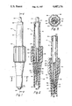
- FIG. 1 is a side elevational view of the flow control valve of the present invention showing how the valve would appear in its exterior configuration
- FIG. 2 is a longitudinal cross-sectional view through the flow control valve of the present invention taken along line 2--2 of FIG. 1 showing the valve in a position permitting a limited flow of fluid to be conducted through the tubing upon which the valve is mounted;
- FIG. 3 is a transverse cross-sectional view taken along line 3--3 of FIG. 1;
- FIG. 4 is a cross-sectional view similar to that of FIG. 2, but showing the valve in a completely closed position.
- the flow control valve 10 of this invention which is formed primarily of an inner tubular member 12 and a collet 14. Both the inner tubular member 12 and the collet 14 will be constructed of a rigid moldable material such as plastic.
- the inner tubular member 12 has an axial bore 16 which is open at both its inner end and its outer end. The outer end is closed by a plug 18.
- the plug 18 includes a central opening 20 within which is fixedly mounted a tube 22.
- the tube 22 is constructed of a plastic material and has a bore 24 through which is to be conducted a fluid from a source (not shown) to be deposited at a depositing location (not shown).
- the type of plastic for the tube 22 can be varied with possibly one particular type of plastic being preferred. However, an important consideration is that if a section of the tube 22 is subjected to a certain elevated temperature, that section of the tube 22 will assume a flaccid configuration. Such a flaccid section as is shown at 26 within the drawing. Basically, the section 22 has lost its memory and in its normal at-rest position the bore 24 within the section 26 is non-circular which is different from the remaining section of the tube 22.
- This flaccid section 26 is located at the inner end of the inner tubular member 12.
- the inner end of the tubular member 12 is formed into a pair of fingers 28 and 30.
- the fingers 28 and 30 oppose each other and are capable of being readily deflected toward each other.
- the interior surface 32 of the finger 28 is formed concave.
- the interior surface 34 of the finger 30 is formed convex. If the convex surface 34 would be permitted to rest within the concave surface 32, such would closely conform thereto. However, in actual practice, this does not occur as the flaccid section 26 will be located between the surfaces 32 and 34.
- the collet 14 Formed on the exterior surface of the inner tubular member 12 is a threaded section 36.
- the collet 14 includes an axial bore 38. This axial bore 38 is open-ended. A portion of this axial bore 38 includes a threaded section 40. The threaded section 40 is in continuous engagement with the threaded section 36. Rotative movement of the collet 14 relative to the inner tubular member 12 will result in longitudinal movement between the collet 14 and the inner tubular member 12.
- a portion of the axial bore 38 includes a cam surface 42.
- This cam surface 42 defines a section of a cone so that the surface 42 assumes a conically tapered configuration. This cam surface 42 is to be in continuous contact with the exterior surface of the fingers 28 and 30.
- valve 10 of this invention is located at the position shown in FIG. 2 of the drawing. In this particular position, the flow of fluid is being conducted through the bore 24 of the tube 22 and is metered through the flaccid section 26 to be deposited at a desired location such as within an intravenous feeding needle which has been mounted within the body of a human being. Let it now be assumed that it is desired to decrease the amount of flow that is being conducted to the human being.
- the operator only needs to rotate the collet 14 relative to the inner tubular member 12. This rotation is achieved manually and grooves 44 are provided within the exterior surface of the collet 14 in order to facilitate this manual movement.
- the volume of fluid which can flow through this section of the bore 24 is decreased depending upon the amount of threading movement between the collet 14 and the inner tubular bore 12 the volume of the fluid passing through the flaccid section 26 can be precisely controlled. In other words, the operator can precisely determine how many drops per minute is being conducted passed the flaccid section 26.
- the collet 14 is of a length to extend past flaccid section 26.
- the flaccid section 26 has no strength or body itself. Therefore, if the collet 14 terminated in the area of the flaccid section 26, there would be a tendency for the tube 22 to kink. However, because the outer end of the collet 14 connects with the normal configuration of the tube 22, the inherent weakness of the flaccid section 26 is bypassed and kinking does not occur.
Landscapes
- Health & Medical Sciences (AREA)
- Heart & Thoracic Surgery (AREA)
- Pulmonology (AREA)
- Engineering & Computer Science (AREA)
- Anesthesiology (AREA)
- Biomedical Technology (AREA)
- Hematology (AREA)
- Life Sciences & Earth Sciences (AREA)
- Animal Behavior & Ethology (AREA)
- General Health & Medical Sciences (AREA)
- Public Health (AREA)
- Veterinary Medicine (AREA)
- Infusion, Injection, And Reservoir Apparatuses (AREA)
Priority Applications (2)
| Application Number | Priority Date | Filing Date | Title |
|---|---|---|---|
| US06/882,840 US4687176A (en) | 1986-07-07 | 1986-07-07 | Flow control valve for a flexible walled tube |
| IT21181/87A IT1221954B (it) | 1986-07-07 | 1987-07-03 | Valvola di controllo di flusso per un tubo a parete flessibile |
Applications Claiming Priority (1)
| Application Number | Priority Date | Filing Date | Title |
|---|---|---|---|
| US06/882,840 US4687176A (en) | 1986-07-07 | 1986-07-07 | Flow control valve for a flexible walled tube |
Publications (1)
| Publication Number | Publication Date |
|---|---|
| US4687176A true US4687176A (en) | 1987-08-18 |
Family
ID=25381446
Family Applications (1)
| Application Number | Title | Priority Date | Filing Date |
|---|---|---|---|
| US06/882,840 Expired - Fee Related US4687176A (en) | 1986-07-07 | 1986-07-07 | Flow control valve for a flexible walled tube |
Country Status (2)
| Country | Link |
|---|---|
| US (1) | US4687176A (it) |
| IT (1) | IT1221954B (it) |
Cited By (7)
| Publication number | Priority date | Publication date | Assignee | Title |
|---|---|---|---|---|
| US5234412A (en) * | 1990-01-25 | 1993-08-10 | Forberg Hans Juergen | Flow regulator for a drip chamber |
| FR2688285A1 (fr) * | 1992-02-28 | 1993-09-10 | Biotrol Sa Lab | Dispositif d'obturation d'un tuyau souple et son procede de fabrication. |
| US5379790A (en) * | 1992-01-31 | 1995-01-10 | Suprex Corporation | Variable restriction |
| EP1125596A3 (en) * | 2000-02-16 | 2002-05-08 | Terumo Kabushiki Kaisha | Intravascular catheter |
| DE102014213576A1 (de) * | 2014-07-11 | 2016-01-14 | B. Braun Melsungen Ag | Durchflussregeleinrichtung für eine Schlauchleitung eines medizinischen Infusionssystems |
| CN115076480A (zh) * | 2022-05-07 | 2022-09-20 | 北京机械设备研究所 | 一种流量可调的输液装置 |
| WO2023192198A1 (en) * | 2022-03-29 | 2023-10-05 | Carefusion 303, Inc. | Intravenous catheter clamps |
Citations (7)
| Publication number | Priority date | Publication date | Assignee | Title |
|---|---|---|---|---|
| US2518625A (en) * | 1946-05-11 | 1950-08-15 | Clinton A Langstaff | Flow bean |
| US3410517A (en) * | 1966-03-15 | 1968-11-12 | Thomas E. Wall | Hose water regulator |
| US3612474A (en) * | 1969-05-09 | 1971-10-12 | Abbott Lab | Flow control device for flexible tubes |
| US3685786A (en) * | 1970-08-31 | 1972-08-22 | Riley D Woodson | Elastic valve element having variable orifice |
| US4205819A (en) * | 1978-06-19 | 1980-06-03 | Emil Soika | Flow clamp device |
| US4453653A (en) * | 1976-05-19 | 1984-06-12 | Michlin Diazo Products Corp. | Collapsible wall closure for dispensers |
| US4512545A (en) * | 1982-06-24 | 1985-04-23 | Dionex Corporation | Externally actuated valve assembly and method |
-
1986
- 1986-07-07 US US06/882,840 patent/US4687176A/en not_active Expired - Fee Related
-
1987
- 1987-07-03 IT IT21181/87A patent/IT1221954B/it active
Patent Citations (7)
| Publication number | Priority date | Publication date | Assignee | Title |
|---|---|---|---|---|
| US2518625A (en) * | 1946-05-11 | 1950-08-15 | Clinton A Langstaff | Flow bean |
| US3410517A (en) * | 1966-03-15 | 1968-11-12 | Thomas E. Wall | Hose water regulator |
| US3612474A (en) * | 1969-05-09 | 1971-10-12 | Abbott Lab | Flow control device for flexible tubes |
| US3685786A (en) * | 1970-08-31 | 1972-08-22 | Riley D Woodson | Elastic valve element having variable orifice |
| US4453653A (en) * | 1976-05-19 | 1984-06-12 | Michlin Diazo Products Corp. | Collapsible wall closure for dispensers |
| US4205819A (en) * | 1978-06-19 | 1980-06-03 | Emil Soika | Flow clamp device |
| US4512545A (en) * | 1982-06-24 | 1985-04-23 | Dionex Corporation | Externally actuated valve assembly and method |
Cited By (9)
| Publication number | Priority date | Publication date | Assignee | Title |
|---|---|---|---|---|
| US5234412A (en) * | 1990-01-25 | 1993-08-10 | Forberg Hans Juergen | Flow regulator for a drip chamber |
| US5379790A (en) * | 1992-01-31 | 1995-01-10 | Suprex Corporation | Variable restriction |
| FR2688285A1 (fr) * | 1992-02-28 | 1993-09-10 | Biotrol Sa Lab | Dispositif d'obturation d'un tuyau souple et son procede de fabrication. |
| EP1125596A3 (en) * | 2000-02-16 | 2002-05-08 | Terumo Kabushiki Kaisha | Intravascular catheter |
| US6482180B2 (en) | 2000-02-16 | 2002-11-19 | Terumo Kabushiki Kaisha | Intravascular catheter |
| DE102014213576A1 (de) * | 2014-07-11 | 2016-01-14 | B. Braun Melsungen Ag | Durchflussregeleinrichtung für eine Schlauchleitung eines medizinischen Infusionssystems |
| WO2023192198A1 (en) * | 2022-03-29 | 2023-10-05 | Carefusion 303, Inc. | Intravenous catheter clamps |
| CN115076480A (zh) * | 2022-05-07 | 2022-09-20 | 北京机械设备研究所 | 一种流量可调的输液装置 |
| CN115076480B (zh) * | 2022-05-07 | 2024-04-09 | 北京机械设备研究所 | 一种流量可调的输液装置 |
Also Published As
| Publication number | Publication date |
|---|---|
| IT1221954B (it) | 1990-08-31 |
| IT8721181A0 (it) | 1987-07-03 |
Similar Documents
| Publication | Publication Date | Title |
|---|---|---|
| US4787406A (en) | Fluid flow control clamp and method for using same | |
| US3841354A (en) | Flow regulating device | |
| US3620500A (en) | Variable aperture fluid flow control apparatus | |
| US3893468A (en) | Clamp for flexible tube and method of regulating flow in such tube | |
| US4550748A (en) | Fluid flow regulating unit for intravascular catheter systems | |
| DE69736754T2 (de) | Extrakorporales Schlitzventil und Steuerung für das Öffnen und Schliessen des Schlitzes | |
| US5397310A (en) | Catheter introducer sheath assembly | |
| US11123484B2 (en) | Pressure responsive fluid flow control valves | |
| US4192303A (en) | Flow regulating device for arterial catheter systems | |
| US5178609A (en) | Medical liquid injector for continuous transfusion | |
| US4176683A (en) | Flow regulator | |
| CN101443060B (zh) | 具有冲洗器的静脉滴注设备控制器 | |
| JP3229833B2 (ja) | 流体搬送装置 | |
| US4869457A (en) | Arrangement for controlling and regulating a liquid flowing through a line | |
| EP0211937A1 (en) | Apparatus for regulating the flow of fluid in medical apparatus | |
| US8597259B2 (en) | Flow controller | |
| US4337770A (en) | Flow regulating device for arterial catheter systems | |
| US4687176A (en) | Flow control valve for a flexible walled tube | |
| US3848634A (en) | Fluid control system for controlling intravenous flow rate | |
| US4589872A (en) | Quick action flow regulator for medical apparatus | |
| US4186740A (en) | Method and apparatus for regulating intravenous flow of a liquid | |
| US4205819A (en) | Flow clamp device | |
| US5599303A (en) | IV administration apparatus | |
| EP0747090B1 (en) | Fluid flow control device, in particular for infusing intravenous fluids | |
| JP2725557B2 (ja) | 薬液注入器具 |
Legal Events
| Date | Code | Title | Description |
|---|---|---|---|
| REMI | Maintenance fee reminder mailed | ||
| LAPS | Lapse for failure to pay maintenance fees | ||
| STCH | Information on status: patent discontinuation |
Free format text: PATENT EXPIRED DUE TO NONPAYMENT OF MAINTENANCE FEES UNDER 37 CFR 1.362 |
|
| FP | Lapsed due to failure to pay maintenance fee |
Effective date: 19910818 |