US4697067A - Steam-generating device and a cooking oven equipped with said device - Google Patents
Steam-generating device and a cooking oven equipped with said device Download PDFInfo
- Publication number
- US4697067A US4697067A US06/821,002 US82100286A US4697067A US 4697067 A US4697067 A US 4697067A US 82100286 A US82100286 A US 82100286A US 4697067 A US4697067 A US 4697067A
- Authority
- US
- United States
- Prior art keywords
- reservoir
- sheet
- water
- steam
- side walls
- Prior art date
- Legal status (The legal status is an assumption and is not a legal conclusion. Google has not performed a legal analysis and makes no representation as to the accuracy of the status listed.)
- Expired - Lifetime
Links
- 238000010411 cooking Methods 0.000 title claims abstract description 15
- XLYOFNOQVPJJNP-UHFFFAOYSA-N water Substances O XLYOFNOQVPJJNP-UHFFFAOYSA-N 0.000 claims abstract description 42
- 239000002184 metal Substances 0.000 claims abstract description 39
- 238000010438 heat treatment Methods 0.000 claims abstract description 35
- 235000013305 food Nutrition 0.000 claims description 7
- 238000005485 electric heating Methods 0.000 claims description 2
- 238000000034 method Methods 0.000 description 4
- 238000009835 boiling Methods 0.000 description 2
- 230000000694 effects Effects 0.000 description 2
- 239000010935 stainless steel Substances 0.000 description 2
- 229910001220 stainless steel Inorganic materials 0.000 description 2
- 150000001298 alcohols Chemical class 0.000 description 1
- 229910045601 alloy Inorganic materials 0.000 description 1
- 239000000956 alloy Substances 0.000 description 1
- 239000012080 ambient air Substances 0.000 description 1
- 125000003118 aryl group Chemical group 0.000 description 1
- 238000010276 construction Methods 0.000 description 1
- 230000007423 decrease Effects 0.000 description 1
- 238000001035 drying Methods 0.000 description 1
- 230000001815 facial effect Effects 0.000 description 1
- 235000008216 herbs Nutrition 0.000 description 1
- 238000004519 manufacturing process Methods 0.000 description 1
- 239000000463 material Substances 0.000 description 1
- 238000012986 modification Methods 0.000 description 1
- 230000004048 modification Effects 0.000 description 1
- 230000002035 prolonged effect Effects 0.000 description 1
- 238000005086 pumping Methods 0.000 description 1
- 238000005507 spraying Methods 0.000 description 1
- 239000000126 substance Substances 0.000 description 1
Images



Classifications
-
- F—MECHANICAL ENGINEERING; LIGHTING; HEATING; WEAPONS; BLASTING
- F22—STEAM GENERATION
- F22B—METHODS OF STEAM GENERATION; STEAM BOILERS
- F22B1/00—Methods of steam generation characterised by form of heating method
- F22B1/28—Methods of steam generation characterised by form of heating method in boilers heated electrically
- F22B1/284—Methods of steam generation characterised by form of heating method in boilers heated electrically with water in reservoirs
-
- A—HUMAN NECESSITIES
- A47—FURNITURE; DOMESTIC ARTICLES OR APPLIANCES; COFFEE MILLS; SPICE MILLS; SUCTION CLEANERS IN GENERAL
- A47J—KITCHEN EQUIPMENT; COFFEE MILLS; SPICE MILLS; APPARATUS FOR MAKING BEVERAGES
- A47J27/00—Cooking-vessels
- A47J27/04—Cooking-vessels for cooking food in steam; Devices for extracting fruit juice by means of steam ; Vacuum cooking vessels
-
- F—MECHANICAL ENGINEERING; LIGHTING; HEATING; WEAPONS; BLASTING
- F24—HEATING; RANGES; VENTILATING
- F24C—DOMESTIC STOVES OR RANGES ; DETAILS OF DOMESTIC STOVES OR RANGES, OF GENERAL APPLICATION
- F24C15/00—Details
-
- F—MECHANICAL ENGINEERING; LIGHTING; HEATING; WEAPONS; BLASTING
- F24—HEATING; RANGES; VENTILATING
- F24C—DOMESTIC STOVES OR RANGES ; DETAILS OF DOMESTIC STOVES OR RANGES, OF GENERAL APPLICATION
- F24C7/00—Stoves or ranges heated by electric energy
- F24C7/006—Stoves or ranges heated by electric energy using electrically heated liquids
Definitions
- the present invention relates to a steam-generating device which is particularly applicable to an electric oven designed for the purpose of cooking food and equipped with the device under consideration.
- a device of this type usually comprises a water reservoir placed in contact with the heating resistors which are mounted in a location close to the bottom wall of the oven.
- Steam is thus generated by boiling the water or by spraying water onto a plate which has been heated to a high temperature.
- the aim of the invention is to overcome these drawbacks by means of a device which is distinguished by the fact that the heating element is placed above the water contained in a reservoir, that two sheet-metal members located in closely spaced relation to each other so as to define a capillary space between them are placed in contact with the heating element and dip into the water contained in the reservoir, one of the sheet-metal members being provided with at least one opening placed in proximity to the heating element.
- the present Applicant has found, surprisingly, that when the heating element is hot, relatively dry steam escapes through the opening formed in one of the sheet-metal members in proximity to the heating element.
- This steam is released without producing ebullition of the water contained in the reservoir since this latter is not in direct contact with the heating element.
- the only direct contact between said heating element and the water contained in the reservoir is provided by the two immersed sheet-metal members.
- the rate of steam delivery can be adjusted by modifying the following parameters : distance between the two sheet-metal members, greater or lesser heat conductivity of said sheet-metal members, distance between the heating element and the water, and heating power of the heating element.
- the distance between the two sheet-metal members is usually of the order of a few tenths of a millimeter.
- the distance between the heating element and the water level, the nature of the sheet-metal members and the dimensions of the capillary space are such that the steam which escapes through the opening formed near the heating element is superheated to a temperature of at least 160° C.
- the steam thus formed has the effect of considerably accelerating the cooking process.
- the invention is also directed to an oven for cooking food and comprising a steam-generating device in accordance with the invention.
- the oven comprising a tubular electric resistor having two parallel legs at the bottom of the oven is provided with a water reservoir of sheet metal placed between the two legs of the heating resistor.
- Said reservoir has two flanges which are formed respectively on two opposite side walls of said reservoir and are adapted to cover each of the two parallel legs of the heating resistor.
- Said water reservoir is closed by a sheet-metal cover having side walls engaged within said reservoir. The side walls of said cover are located in closely spaced relation to the side walls of the reservoir and immersed in the water of the reservoir so as to form a capillary space between said walls.
- Said capillary space opens to the exterior in the zone located between the two flanges and the adjacent edge of the top wall of the cover.
- the steam escapes through the slits defined between the flanges of the reservoir and the adjacent edge of the top wall of the cover.
- the steam-generating device does not take up any space within the oven itself.
- the arrangement of the slits for the release of steam along the heating resistors permits excellent distribution of steam within the oven, thus permitting greater uniformity of temperature distribution within the oven and therefore more efficient cooking of food.
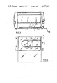
- FIG. 1 is a sectional view which is perpendicular to the heating element and shows a first embodiment of the device in accordance with the invention
- FIG. 2 is a top view of the device
- FIG. 3 is a longitudinal sectional view of a cooking oven equipped with a device in accordance with the invention ;
- FIG. 4 is a top view of the oven after removal of its upper portion ;
- FIG. 5 is a sectional view to a larger scale, this view being taken along the plane V--V of FIG. 4 ;
- FIG. 6 is a top view of the device shown in FIG. 5 ;
- FIG. 7 is a view which is similar to FIGS. 1 and 5 and relates to an alternative embodiment ;
- FIG. 8 is a top view of the device shown in FIG. 7 ;
- FIG. 9 is a longitudinal sectional view which is perpendicular to the view of FIG. 5 and shows an alternative embodiment ;
- FIG. 10 is a sectional view taken along the plane X--X of FIG. 9.
- the steam-generating device comprises a heating element 1 consisting of a tubular electric resistor and a reservoir 2 containing the water 3.
- the heating element 1 is placed above the water 3 contained in the reservoir 2.
- Two sheet-metal members 4, 5 located in closely spaced relation to each other in order to define a capillary space 6 between said members are placed in contact with the heating element 1 and immersed in the water 3 of the reservoir 2.
- the sheet-metal member 5 is provided with openings 7 which are placed directly above the heating element 1.
- the distance between the two sheet-metal members 4, 5 is of the order of a few tenths of a millimeter.
- said sheet-metal members 4, 5 can be of stainless steel.
- the two sheet-metal members 4, 5 are bent to a U-shaped cross-section and cover the heating element 1 in such a manner as to ensure that the base of the U is in contact with the heating element 1 and that the two arms of the U formed by the two sheet-metal members dip into the water 3 of the reservoir 2.
- the openings 7 are formed in the outer sheet-metal member 5 along a line located above the heating element 1 in a vertical plane which passes through the axis of said element.
- the water 3 tends to rise within said gap under the action of capillarity and thermal pumping.
- the water contained in the reservoir does not come to the boil under any circumstances since the sheet-metal member 4, 5 is of small thickness (less than 1 mm) and does not establish a sufficient thermal contact with the water to produce ebullition.
- FIGS. 3 and 4 there is shown an electric oven for cooking food, comprising a steam-generating device 8 in accordance with the invention.
- Said oven has a tubular electric heating resistor 9 in the form of two legs 9a, 9b which are parallel to the bottom wall 10 of the oven. As shown in FIGS. 5 and 6, a water reservoir 11 of sheet metal is placed between the two legs 9a, 9b of said heating resistor 9.
- said reservoir 11 has two flanges 12, 13 formed respectively on two opposite side walls 14, 15 of said reservoir.
- the flanges 12, 13 respectively are adapted to cover each of the two parallel legs 9a, 9b of the heating resistor 9.
- the reservoir 11 is closed by a cover 16 which is also formed of thin sheet metal and has side walls 17, 18 located in closely spaced relation to the side walls 14, 15 of the reservoir 11 and immersed in the water of said reservoir, thus forming an intermediate capillary space 19 which opens to the exterior through a slit 20 formed between the two flanges 12, 13 and the adjacent edge 21 of the top wall 22 of the cover 16.
- the reservoir 11 is engaged within an opening 23 formed in the bottom wall 10 of the oven, with the result that the bottom wall 24 of the reservoir 11 is in contact with the exterior of the oven or the reservoir 11 is in contact with the external wall of said oven (see dashed line in FIG. 5).
- the resistor 9 When the resistor 9 is in the hot state, the water which has risen within the capillary space 19 vaporizes and escapes through the slits 20 placed along the resistor legs 9a, 9b.
- the steam discharged through the slits is superheated to a temperature within the range of 160° C. to 200° C., depending on the distance between the heating element and the level of the water contained in the reservoir.
- the water contained in the reservoir 11 is not liable to boil since the heat generated by the resistor 9 is not directly transmitted to the water contained in the reservoir. Furthermore, this water is cooled by the bottom wall 24 of the reservoir which is in contact with the exterior of the oven.
- the present Applicant has shown that aromatic substances (herbs or alcohols) could be added to the water contained in the reservoir 11, thus having the effect of scenting the steam produced by the device without affecting its operation.
- the device in accordance with the invention offers a further advantage in that it is very simple to construct, that it can readily be cleaned and can be removed from the oven and replaced with great ease.
- the steam-generating device also comprises two sheet-metal members 25, 26 bent to a U-shaped cross-section and located in closely spaced relation to each other.
- the side walls of said sheet-metal members 25, 26 dip into the water 3 of the reservoir 27 and the lower ends of said side walls are in contact with the bottom reservoir wall 28 which serves as a support for said sheet-metal members.
- the base of the U formed by the sheet-metal members 25, 26 has a channel portion 29 which is directed towards the bottom wall 28 of the reservoir 27 and partly follows the contour of the heating resistor 1.
- Two series of openings 30 are formed in the outer sheet-metal member 25 along two lines parallel to the resistor 1 and located on each side of the channel portion 29.
- the sheet-metal member employed for constructing the device in accordance with the invention can be of a metal or alloy other than stainless steel on condition that the material employed affords resistance to the prolonged action of high temperatures, of water and of steam and that its thermal conductivity is neither too high nor too low.
- the surface state of the metal may also be modified by a suitable treatment (sanding or burnishing, for example) in order to vary the rate of flow of water.
- the space formed between the two sheet-metal members can be adjusted with accuracy by placing shims of small thickness between said sheet-metal members or by forming wavy corrugations of small amplitude on one of said members.
- means are provided for varying the rate of steam delivery between the beginning and end of the cooking process, that is, between the moment when the vessel 11 is full and the moment when this latter is nearly empty.
- a recessed portion 31 having the shape of an inverted V or in other words downwardly flared, the summit 32 of said recessed portion 31 being located near the maximum level of the water contained in the reservoir 31. It is observed that, by virtue of said recessed portion 31, the flow rate of steam delivered at 20 and 21 is of maximum value at the start of the cooking process, then decreases progressively as the water level drops within the vessel. It is thus possible to program the rate of steam delivery as a function of the cooking time.
- recessed portion mentioned in the foregoing could also be formed on the walls 26 of the device shown in the alternative embodiment of FIG. 7.
Landscapes
- Engineering & Computer Science (AREA)
- Mechanical Engineering (AREA)
- General Engineering & Computer Science (AREA)
- Combustion & Propulsion (AREA)
- Chemical & Material Sciences (AREA)
- Food Science & Technology (AREA)
- Thermal Sciences (AREA)
- Physics & Mathematics (AREA)
- Life Sciences & Earth Sciences (AREA)
- Sustainable Energy (AREA)
- Sustainable Development (AREA)
- Cookers (AREA)
- Baking, Grill, Roasting (AREA)
- Electric Stoves And Ranges (AREA)
- General Preparation And Processing Of Foods (AREA)
- Heat Treatment Of Water, Waste Water Or Sewage (AREA)
Applications Claiming Priority (2)
| Application Number | Priority Date | Filing Date | Title |
|---|---|---|---|
| FR8501053 | 1985-01-25 | ||
| FR8501053A FR2576669B1 (fr) | 1985-01-25 | 1985-01-25 | Dispositif pour produire de la vapeur d'eau et four de cuisson comportant un tel dispositif. |
Publications (1)
| Publication Number | Publication Date |
|---|---|
| US4697067A true US4697067A (en) | 1987-09-29 |
Family
ID=9315607
Family Applications (1)
| Application Number | Title | Priority Date | Filing Date |
|---|---|---|---|
| US06/821,002 Expired - Lifetime US4697067A (en) | 1985-01-25 | 1986-01-22 | Steam-generating device and a cooking oven equipped with said device |
Country Status (9)
| Country | Link |
|---|---|
| US (1) | US4697067A (de) |
| EP (1) | EP0190954B1 (de) |
| JP (1) | JPS61173025A (de) |
| AT (1) | ATE38423T1 (de) |
| DE (2) | DE190954T1 (de) |
| EG (1) | EG17531A (de) |
| ES (1) | ES296834Y (de) |
| FR (1) | FR2576669B1 (de) |
| HK (1) | HK6990A (de) |
Cited By (10)
| Publication number | Priority date | Publication date | Assignee | Title |
|---|---|---|---|---|
| US4851644A (en) * | 1987-05-14 | 1989-07-25 | Delaware Capital Formation, Inc. | Electric combination oven |
| US4924072A (en) * | 1987-05-14 | 1990-05-08 | Delaware Capital Formation, Inc. | Humidity control for oven chamber |
| US5237144A (en) * | 1990-06-18 | 1993-08-17 | Nikko Co., Ltd. | Electromagnetic induction heater |
| US5256382A (en) * | 1989-03-10 | 1993-10-26 | Autocar Equipment Limited | Vapor-heated chamber |
| KR20030008755A (ko) * | 2001-07-20 | 2003-01-29 | 주식회사공간코리아 | 다공가열판을 이용한 수증기 발생장치 |
| US20040011222A1 (en) * | 2000-11-01 | 2004-01-22 | Fisher David Simon | Deck oven |
| WO2010083387A2 (en) | 2009-01-16 | 2010-07-22 | Mag Aerospace Industries, Inc. | Oven steam generator systems and methods |
| US20170157344A1 (en) * | 2006-01-31 | 2017-06-08 | Philip Morris Usa Inc. | Bent capillary tube aerosol generator |
| US10743701B2 (en) | 2016-08-01 | 2020-08-18 | E.G.O. Elektro-Geraetebau Gmbh | Evaporator device for water and steamer having an evaporator device of this kind |
| US20220330556A1 (en) * | 2021-04-19 | 2022-10-20 | Electrolux Home Products, Inc. | Steam cooking system |
Families Citing this family (5)
| Publication number | Priority date | Publication date | Assignee | Title |
|---|---|---|---|---|
| FR2614976B1 (fr) * | 1987-05-06 | 1990-03-09 | Seb Sa | Four electrique pour la cuisson des aliments comprenant un generateur de vapeur |
| DE3844144A1 (de) * | 1988-12-28 | 1990-07-05 | Ernst Kirchhoff | Waermvorrichtung fuer lebensmittel |
| JP4923258B2 (ja) * | 2006-02-14 | 2012-04-25 | 国立大学法人横浜国立大学 | 過熱水蒸気発生装置及び過熱水蒸気発生方法 |
| DE102006050368B4 (de) | 2006-10-25 | 2022-08-25 | BSH Hausgeräte GmbH | Gargerät zum Garen von Lebensmitteln mittels Dampf |
| JP5413807B2 (ja) * | 2009-11-05 | 2014-02-12 | 茂利 谷川 | 瞬間加熱装置 |
Citations (9)
| Publication number | Priority date | Publication date | Assignee | Title |
|---|---|---|---|---|
| US1749969A (en) * | 1928-01-03 | 1930-03-11 | Brodin Arvid | Water heater |
| GB502841A (en) * | 1938-04-13 | 1939-03-27 | Richard Francis Campbell | Improvements in steamers for domestic and such-like purposes |
| US2668993A (en) * | 1950-08-07 | 1954-02-16 | Julian H Bair | Electrically heated vaporizer |
| US3080624A (en) * | 1963-03-12 | weber iii | ||
| US3379855A (en) * | 1963-05-13 | 1968-04-23 | Electro Optical Systems Inc | Fluid feed system |
| US3639725A (en) * | 1971-03-03 | 1972-02-01 | Thomas J Maniscalco | Steam-generating apparatus |
| US3672568A (en) * | 1970-08-12 | 1972-06-27 | Foote Allen | Humidifier |
| US3891826A (en) * | 1972-08-05 | 1975-06-24 | Eberhard Seuthe | Electrically heated smoke or steam generator |
| US4419302A (en) * | 1979-09-29 | 1983-12-06 | Matsushita Electric Industrial Company, Limited | Steam generator |
Family Cites Families (1)
| Publication number | Priority date | Publication date | Assignee | Title |
|---|---|---|---|---|
| JPS5321202U (de) * | 1976-08-03 | 1978-02-22 |
-
1985
- 1985-01-25 FR FR8501053A patent/FR2576669B1/fr not_active Expired
-
1986
- 1986-01-15 DE DE198686400074T patent/DE190954T1/de active Pending
- 1986-01-15 EP EP86400074A patent/EP0190954B1/de not_active Expired
- 1986-01-15 DE DE8686400074T patent/DE3661105D1/de not_active Expired
- 1986-01-15 AT AT86400074T patent/ATE38423T1/de not_active IP Right Cessation
- 1986-01-22 US US06/821,002 patent/US4697067A/en not_active Expired - Lifetime
- 1986-01-23 EG EG33/86A patent/EG17531A/xx active
- 1986-01-24 ES ES1986296834U patent/ES296834Y/es not_active Expired
- 1986-01-24 JP JP61012272A patent/JPS61173025A/ja active Granted
-
1990
- 1990-01-25 HK HK69/90A patent/HK6990A/xx not_active IP Right Cessation
Patent Citations (9)
| Publication number | Priority date | Publication date | Assignee | Title |
|---|---|---|---|---|
| US3080624A (en) * | 1963-03-12 | weber iii | ||
| US1749969A (en) * | 1928-01-03 | 1930-03-11 | Brodin Arvid | Water heater |
| GB502841A (en) * | 1938-04-13 | 1939-03-27 | Richard Francis Campbell | Improvements in steamers for domestic and such-like purposes |
| US2668993A (en) * | 1950-08-07 | 1954-02-16 | Julian H Bair | Electrically heated vaporizer |
| US3379855A (en) * | 1963-05-13 | 1968-04-23 | Electro Optical Systems Inc | Fluid feed system |
| US3672568A (en) * | 1970-08-12 | 1972-06-27 | Foote Allen | Humidifier |
| US3639725A (en) * | 1971-03-03 | 1972-02-01 | Thomas J Maniscalco | Steam-generating apparatus |
| US3891826A (en) * | 1972-08-05 | 1975-06-24 | Eberhard Seuthe | Electrically heated smoke or steam generator |
| US4419302A (en) * | 1979-09-29 | 1983-12-06 | Matsushita Electric Industrial Company, Limited | Steam generator |
Cited By (18)
| Publication number | Priority date | Publication date | Assignee | Title |
|---|---|---|---|---|
| US4924072A (en) * | 1987-05-14 | 1990-05-08 | Delaware Capital Formation, Inc. | Humidity control for oven chamber |
| US4851644A (en) * | 1987-05-14 | 1989-07-25 | Delaware Capital Formation, Inc. | Electric combination oven |
| US5256382A (en) * | 1989-03-10 | 1993-10-26 | Autocar Equipment Limited | Vapor-heated chamber |
| US5237144A (en) * | 1990-06-18 | 1993-08-17 | Nikko Co., Ltd. | Electromagnetic induction heater |
| US20040011222A1 (en) * | 2000-11-01 | 2004-01-22 | Fisher David Simon | Deck oven |
| US6900414B2 (en) * | 2000-11-01 | 2005-05-31 | Aga Foodservice Equipment Limited | Deck oven |
| KR20030008755A (ko) * | 2001-07-20 | 2003-01-29 | 주식회사공간코리아 | 다공가열판을 이용한 수증기 발생장치 |
| US20170157344A1 (en) * | 2006-01-31 | 2017-06-08 | Philip Morris Usa Inc. | Bent capillary tube aerosol generator |
| US10792442B2 (en) * | 2006-01-31 | 2020-10-06 | Philip Morris Usa Inc. | Bent capillary tube aerosol generator |
| US20100230396A1 (en) * | 2009-01-16 | 2010-09-16 | Abdelaziz Boubeddi | Oven Steam Generator Systems and Methods |
| WO2010083387A3 (en) * | 2009-01-16 | 2011-11-24 | Mag Aerospace Industries, Inc. | Oven steam generator system and method for generating steam |
| US8288690B2 (en) | 2009-01-16 | 2012-10-16 | Mag Aerospace Industries, Inc. | Oven steam generator systems and methods |
| US8581151B2 (en) | 2009-01-16 | 2013-11-12 | Mag Aerospace Industries, Inc. | Steam oven water delivery and drain valve systems and methods |
| US20110100477A1 (en) * | 2009-01-16 | 2011-05-05 | Mag Aerospace Industries, Inc. D/B/A Monogram Systems | Steam oven water delivery and drain valve systems and methods |
| WO2010083387A2 (en) | 2009-01-16 | 2010-07-22 | Mag Aerospace Industries, Inc. | Oven steam generator systems and methods |
| US10743701B2 (en) | 2016-08-01 | 2020-08-18 | E.G.O. Elektro-Geraetebau Gmbh | Evaporator device for water and steamer having an evaporator device of this kind |
| US20220330556A1 (en) * | 2021-04-19 | 2022-10-20 | Electrolux Home Products, Inc. | Steam cooking system |
| US12433297B2 (en) * | 2021-04-19 | 2025-10-07 | Electrolux Consumer Products, Inc. | Steam cooking system |
Also Published As
| Publication number | Publication date |
|---|---|
| EG17531A (en) | 1989-09-30 |
| DE3661105D1 (en) | 1988-12-08 |
| JPH0322538B2 (de) | 1991-03-27 |
| EP0190954A1 (de) | 1986-08-13 |
| HK6990A (en) | 1990-02-02 |
| EP0190954B1 (de) | 1988-11-02 |
| ATE38423T1 (de) | 1988-11-15 |
| ES296834Y (es) | 1988-09-16 |
| DE190954T1 (de) | 1986-12-18 |
| FR2576669B1 (fr) | 1987-04-30 |
| FR2576669A1 (fr) | 1986-08-01 |
| JPS61173025A (ja) | 1986-08-04 |
| ES296834U (es) | 1988-01-16 |
Similar Documents
| Publication | Publication Date | Title |
|---|---|---|
| US4697067A (en) | Steam-generating device and a cooking oven equipped with said device | |
| US4509412A (en) | Food steaming device | |
| JPS5829361Y2 (ja) | 加熱調理装置のタ−ンテ−ブル | |
| US3212426A (en) | Apparatus for cooking | |
| US3292528A (en) | Broiler grid and pan | |
| US6906289B2 (en) | Apparatus for heating a vessel containing foodstuffs | |
| KR101083993B1 (ko) | 전열 증기 취사기 | |
| US4700050A (en) | Heater clamping arrangement for electrically heated boilers | |
| KR20050107677A (ko) | 이중 가열식 냄비 구조 | |
| US3485163A (en) | Steam cooker | |
| US1994331A (en) | Apparatus for evaporating liquids | |
| US4728778A (en) | Cooking apparatus | |
| US4170931A (en) | Heating device for a percolator and method of using the same | |
| US5943949A (en) | Indoor grille | |
| US448886A (en) | Apparatus for baking | |
| JP3864529B2 (ja) | 加熱調理器 | |
| KR200157308Y1 (ko) | 찜통용 응축수 유도판 | |
| US2515641A (en) | Electrically heated plate | |
| JP3932638B2 (ja) | 加熱調理器 | |
| CN111035231A (zh) | 蒸发器设备以及具有蒸发器设备的电气器具 | |
| CN219661423U (zh) | 一种蒸汽烹饪装置 | |
| US965636A (en) | Roasting-pan. | |
| CN213129168U (zh) | 炊具盖体蒸汽定向凝结结构 | |
| SU1268891A1 (ru) | Конфорка электроплиты | |
| US3185145A (en) | Heater for drums |
Legal Events
| Date | Code | Title | Description |
|---|---|---|---|
| AS | Assignment |
Owner name: SEB S.A., 21260 SELONGEY, FRANCE, A FRENCH COMPANY Free format text: ASSIGNMENT OF ASSIGNORS INTEREST.;ASSIGNORS:ROSSET, ROGER;MAYEUR, JACQUES;REEL/FRAME:004509/0694 Effective date: 19851223 |
|
| STCF | Information on status: patent grant |
Free format text: PATENTED CASE |
|
| FEPP | Fee payment procedure |
Free format text: PAYOR NUMBER ASSIGNED (ORIGINAL EVENT CODE: ASPN); ENTITY STATUS OF PATENT OWNER: LARGE ENTITY |
|
| FPAY | Fee payment |
Year of fee payment: 4 |
|
| FPAY | Fee payment |
Year of fee payment: 8 |
|
| FEPP | Fee payment procedure |
Free format text: PAYER NUMBER DE-ASSIGNED (ORIGINAL EVENT CODE: RMPN); ENTITY STATUS OF PATENT OWNER: LARGE ENTITY Free format text: PAYOR NUMBER ASSIGNED (ORIGINAL EVENT CODE: ASPN); ENTITY STATUS OF PATENT OWNER: LARGE ENTITY |
|
| FPAY | Fee payment |
Year of fee payment: 12 |