US4698909A - Fastener splitter device - Google Patents
Fastener splitter device Download PDFInfo
- Publication number
- US4698909A US4698909A US06/829,596 US82959686A US4698909A US 4698909 A US4698909 A US 4698909A US 82959686 A US82959686 A US 82959686A US 4698909 A US4698909 A US 4698909A
- Authority
- US
- United States
- Prior art keywords
- cutter
- fastener
- nut
- edges
- frame
- Prior art date
- Legal status (The legal status is an assumption and is not a legal conclusion. Google has not performed a legal analysis and makes no representation as to the accuracy of the status listed.)
- Expired - Fee Related
Links
Images

Classifications
-
- B—PERFORMING OPERATIONS; TRANSPORTING
- B23—MACHINE TOOLS; METAL-WORKING NOT OTHERWISE PROVIDED FOR
- B23D—PLANING; SLOTTING; SHEARING; BROACHING; SAWING; FILING; SCRAPING; LIKE OPERATIONS FOR WORKING METAL BY REMOVING MATERIAL, NOT OTHERWISE PROVIDED FOR
- B23D29/00—Hand-held metal-shearing or metal-cutting devices
- B23D29/007—Hand-held metal-shearing or metal-cutting devices for splitting nuts
-
- B—PERFORMING OPERATIONS; TRANSPORTING
- B21—MECHANICAL METAL-WORKING WITHOUT ESSENTIALLY REMOVING MATERIAL; PUNCHING METAL
- B21J—FORGING; HAMMERING; PRESSING METAL; RIVETING; FORGE FURNACES
- B21J15/00—Riveting
- B21J15/38—Accessories for use in connection with riveting, e.g. pliers for upsetting; Hand tools for riveting
- B21J15/50—Removing or cutting devices for rivets
-
- B—PERFORMING OPERATIONS; TRANSPORTING
- B25—HAND TOOLS; PORTABLE POWER-DRIVEN TOOLS; MANIPULATORS
- B25B—TOOLS OR BENCH DEVICES NOT OTHERWISE PROVIDED FOR, FOR FASTENING, CONNECTING, DISENGAGING, OR HOLDING
- B25B27/00—Hand tools, specially adapted for fitting together or separating parts or objects whether or not involving some deformation, not otherwise provided for
- B25B27/14—Hand tools, specially adapted for fitting together or separating parts or objects whether or not involving some deformation, not otherwise provided for for assembling objects other than by press fit or detaching same
- B25B27/18—Hand tools, specially adapted for fitting together or separating parts or objects whether or not involving some deformation, not otherwise provided for for assembling objects other than by press fit or detaching same withdrawing broken threaded parts or twist drills
Definitions
- the invention relates to a splitter device for splitting fasteners, in particular, nuts.
- Nuts have frequently to be removed from male threaded parts such as studs or bolts on which they have been placed, for example to allow equipment to be dismantled, and this is often difficult because the effects of corrosion make it impossible to turn the nut under the force that can be applied manually by a spanner. Nuts that cannot be released by ordinary means can be chiselled off by brute force or burnt off by oxy-acetylene torches but neither of these methods is to be recommended because of safety factors and the risk of damage. Instead, the nuts can be removed in a more controlled manner by use of a proprietary nut splitter tool or device.
- the device shown in FIG. 1 comprises a frame 1 with an interior in which can be received a screwthreaded nut 2 received on a stud or a bolt 4 provided with a mating external screw thread.
- a cutter blade 5 is guided by the frame for movement towards and away from the nut 2 as indicated by the arrow 6. To split the nut 2, the blade 5 is moved into cutting engagement with it, hydraulically or mechanically, in a linear manner, reacting against the frame 1.
- FIG. 1 It is a disadvantage of the device of FIG. 1 that it merely splits the nut 2 apart by a small amount, as shown at 7 in FIG. 2, and causes damage to the bolt 4.
- the nut 1 remains in situ on the bolt 4 and is distorted by the cutting operation so as to be no longer of a shape to suit regular spanners.
- the split nut 2 can be rotated through 180° and cut again, but the technique is less than satisfactory especially when work is being done under difficult conditions, for example in undersea locations.
- the invention accordingly has as its object the provision of a fastener splitter device in which the above-mentioned disadvantages are avoided.
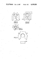
- FIG. 1 is a schematic partial plan view of a first prior art nut splitter.
- FIG. 2 is a like view of a nut split by the device of FIG. 1.
- FIG. 3 is a view resembling that of FIG. 1 of a second prior art nut splitter device.
- FIG. 4 is a schematic plan view of the nut splitting device embodying the invention.
- FIG. 5 is a like view of a nut split by the device of FIG. 4.
- the invention accordingly provides a splitter tool or device comprising a cutter movable relative to an abutment to engage a fastener to be split, for example, a nut, held by the abutment, the cutter having blades positioned to engage the fastener at spaced-apart locations.
- a device in accordance with the invention can thus cut the nut or other fastener at two positions which are spaced part but located on the same side of the nut, so that the nut is split into two unequal portions.
- the spacing of the two blades of the cutter can be such that the two parts of the split nut can readily be removed and there is no risk of damage to the stud or bolt.
- the frame portion for backing the nut against the cutter blade can of course be of the minimum dimensions needed for strength adequate to resist the cutting force, so that no very great clearance is required on the side of the nut opposite the cutter.
- the cutter can be shaped so as to force apart the larger portion of the nut remaining, so as to facilitate its removal.
- the illustrated nut splitter tool or device of the invention comprises a frame 20 having spaced parallel side portions 21 joined together at one end by inwardly inclined portions 22 and a transverse end portion 24, which defines with the portions 22 a space within the frame for the reception of a hexagonal nut 25 received on the threaded end of a bolt 26.
- the inner face of the end portion 24 is formed with a central convex projection 27 which functions as a fulcrum for the nut, and the portions 22 diverge from the end portion 22 at angles in excess of 60° to allow clearance, at 29, for distortion of the nut when split.
- the device includes a cutter 30 guided by the side portions 21 for reciprocal movement between them towards and away from the end portion 24.
- the cutter 30 is provided with guide portions 31 extending into grooves 32 formed on the inner faces of the side portions.
- the cutter 30 is driven towards the frame end portion 24 under power supplied by a suitable drive arrangement for example a hydraulic cylinder 33 mounted at the other end of the frame as shown.
- the cutter 30 has two spaced parallel blade edges 35 extending in use parallel to the axis of the nut 25 and in a plane perpendicular to the direction of movement of the cutter 30.
- the length of the blade edges 35 is at least the axial length of the nut and the edges are spaced apart by slightly less than the width of the end portion 24, so as to engage the nut adjacent the ends of the side face opposite the side face engaged by the frame end projection 27.
- the blade edges can be spaced apart by an amount slightly less than the diameter of the bolt 26.
- the cutter 30 has between the blade edges 35 a generally U-shaped recess the sides of which slightly diverge inwardly through a small back-off angle a of the order of 2°. Externally, the cutter 30 is flared outwardly from the blade edges through an angle b, normally in the range of from 20° to 45°.
- the frame 20 is placed over the nut 25 irremovably received on the bolt 26 in the position shown in FIG. 4, and the hydraulic cylinder 33 is operated to advance the cutter 30 to engage the blade edges 35 against the adjacent face of the nut.
- the cutter 30 effects cutting of the nut at two positions simultaneously, and, because of the external shape of the cutter 30, this acts to open the major portion of the nut so additionally applying a tensile stress to the weakening part of the nut.
- the nut 25 fails in tension so that a segment 25A, as shown in FIG. 5, is separated from the rest of the nut, before the blade edges 35 reach the thread of the bolt 26, so that the thread is undamaged.
- the cutter 30 can now be withdrawn and the separated segment 25A of the nut in the recess of the cutter can be freed. Jamming of the segment 25A in the recess is prevented by the inward divergence of its side walls. The remainder of the nut 25 has been opened up, by distortion into the clearances 29, to such an extent that it is separated from the bolt and can readily be removed.
Landscapes
- Engineering & Computer Science (AREA)
- Mechanical Engineering (AREA)
- Dowels (AREA)
- Crushing And Pulverization Processes (AREA)
- Input Circuits Of Receivers And Coupling Of Receivers And Audio Equipment (AREA)
- Shovels (AREA)
- Scissors And Nippers (AREA)
- Shearing Machines (AREA)
- Vehicle Body Suspensions (AREA)
- Absorbent Articles And Supports Therefor (AREA)
- Knives (AREA)
- Headphones And Earphones (AREA)
- Liquid Developers In Electrophotography (AREA)
- Graft Or Block Polymers (AREA)
Applications Claiming Priority (2)
| Application Number | Priority Date | Filing Date | Title |
|---|---|---|---|
| GB858503777A GB8503777D0 (en) | 1985-02-14 | 1985-02-14 | Nut splitter device |
| GB8503777 | 1985-02-14 |
Publications (1)
| Publication Number | Publication Date |
|---|---|
| US4698909A true US4698909A (en) | 1987-10-13 |
Family
ID=10574470
Family Applications (1)
| Application Number | Title | Priority Date | Filing Date |
|---|---|---|---|
| US06/829,596 Expired - Fee Related US4698909A (en) | 1985-02-14 | 1986-02-13 | Fastener splitter device |
Country Status (7)
| Country | Link |
|---|---|
| US (1) | US4698909A (de) |
| EP (1) | EP0192409B1 (de) |
| JP (1) | JPS61219513A (de) |
| AT (1) | ATE40066T1 (de) |
| DE (1) | DE3661801D1 (de) |
| GB (1) | GB8503777D0 (de) |
| NO (1) | NO159708C (de) |
Cited By (10)
| Publication number | Priority date | Publication date | Assignee | Title |
|---|---|---|---|---|
| US4807348A (en) * | 1986-11-04 | 1989-02-28 | Huck Manufacturing Company | Hydraulically actuated lockbolt collar cutter and method of cutting a collar |
| US5479710A (en) * | 1991-06-28 | 1996-01-02 | Hydra-Tight Limited | Nut splitters |
| US20020170406A1 (en) * | 2000-12-07 | 2002-11-21 | Corporacion Nacional Del Cobre De Chile | Device for the maintenance of semi-autogenous grinding mills used in large-scale mining |
| US20040200320A1 (en) * | 2003-04-11 | 2004-10-14 | Brian Knopp | Hydraulic torque wrench system |
| US20040255470A1 (en) * | 2003-06-20 | 2004-12-23 | Spx Corporation | Tool force transmitting method and apparatus |
| US20060021207A1 (en) * | 2003-09-03 | 2006-02-02 | Haines Donald W Jr | Fastener removal apparatus and associated method |
| US20060090321A1 (en) * | 2004-11-03 | 2006-05-04 | Huck International, Inc. | Apparatus for removing fasteners and method regarding same |
| WO2020229488A1 (de) * | 2019-05-15 | 2020-11-19 | Airbus Operations Gmbh | Verfahren zur demontage eines blindniets in einer werkstückanordnung |
| CN114749716A (zh) * | 2022-05-17 | 2022-07-15 | 湖南山德维克矿山装备制造有限责任公司 | 一种矿用柱形锚具自动解剖器 |
| US11717899B2 (en) * | 2017-08-09 | 2023-08-08 | The Boeing Company | Lock bolt collar removal tool |
Families Citing this family (3)
| Publication number | Priority date | Publication date | Assignee | Title |
|---|---|---|---|---|
| AU588712B2 (en) * | 1986-11-04 | 1989-09-21 | Huck International, Inc. | A hydraulically actuated lockbolt collar cutter and method of cutting a collar |
| JPH01129018U (de) * | 1988-02-23 | 1989-09-04 | ||
| DE29507215U1 (de) * | 1995-04-29 | 1995-06-29 | Seppelfricke Haus- und Küchentechnik GmbH, 45881 Gelsenkirchen | Vorrichtung zum Demontieren von Elektrodenkappen |
Citations (6)
| Publication number | Priority date | Publication date | Assignee | Title |
|---|---|---|---|---|
| US285868A (en) * | 1883-10-02 | Bolt-cutter | ||
| US1156745A (en) * | 1915-05-01 | 1915-10-12 | Joseph D Brady | Tool for splitting nuts. |
| US3992777A (en) * | 1976-03-22 | 1976-11-23 | Nut Cutters, Inc. | Tool for releasing a nut threaded onto a bolt |
| US4246699A (en) * | 1978-07-17 | 1981-01-27 | Cliff Van Riper | Nut cutting or nut breaking tool |
| US4257163A (en) * | 1979-04-27 | 1981-03-24 | Wolfgang Bauer | Automotive service tool |
| US4285126A (en) * | 1979-09-04 | 1981-08-25 | Lawrence Irwin F | Hydraulically actuated apparatus |
Family Cites Families (2)
| Publication number | Priority date | Publication date | Assignee | Title |
|---|---|---|---|---|
| GB1148432A (en) * | 1966-02-23 | 1969-04-10 | Ici Ltd | Tool for splitting hollow bodies |
| GB1601772A (en) * | 1978-03-21 | 1981-11-04 | Gkn Bolts & Nuts Ltd | Device for splitting nuts |
-
1985
- 1985-02-14 GB GB858503777A patent/GB8503777D0/en active Pending
-
1986
- 1986-02-12 EP EP86300957A patent/EP0192409B1/de not_active Expired
- 1986-02-12 DE DE8686300957T patent/DE3661801D1/de not_active Expired
- 1986-02-12 AT AT86300957T patent/ATE40066T1/de not_active IP Right Cessation
- 1986-02-13 US US06/829,596 patent/US4698909A/en not_active Expired - Fee Related
- 1986-02-13 NO NO860528A patent/NO159708C/no unknown
- 1986-02-14 JP JP61029173A patent/JPS61219513A/ja active Pending
Patent Citations (6)
| Publication number | Priority date | Publication date | Assignee | Title |
|---|---|---|---|---|
| US285868A (en) * | 1883-10-02 | Bolt-cutter | ||
| US1156745A (en) * | 1915-05-01 | 1915-10-12 | Joseph D Brady | Tool for splitting nuts. |
| US3992777A (en) * | 1976-03-22 | 1976-11-23 | Nut Cutters, Inc. | Tool for releasing a nut threaded onto a bolt |
| US4246699A (en) * | 1978-07-17 | 1981-01-27 | Cliff Van Riper | Nut cutting or nut breaking tool |
| US4257163A (en) * | 1979-04-27 | 1981-03-24 | Wolfgang Bauer | Automotive service tool |
| US4285126A (en) * | 1979-09-04 | 1981-08-25 | Lawrence Irwin F | Hydraulically actuated apparatus |
Cited By (22)
| Publication number | Priority date | Publication date | Assignee | Title |
|---|---|---|---|---|
| US4807348A (en) * | 1986-11-04 | 1989-02-28 | Huck Manufacturing Company | Hydraulically actuated lockbolt collar cutter and method of cutting a collar |
| US5479710A (en) * | 1991-06-28 | 1996-01-02 | Hydra-Tight Limited | Nut splitters |
| US6869001B2 (en) | 2000-12-07 | 2005-03-22 | Corporacion Nacional Del Cobre De Chile | Device for the maintenance of semi-autogenous grinding mills used in large-scale mining |
| US20020170406A1 (en) * | 2000-12-07 | 2002-11-21 | Corporacion Nacional Del Cobre De Chile | Device for the maintenance of semi-autogenous grinding mills used in large-scale mining |
| EP1213078A3 (de) * | 2000-12-07 | 2004-03-24 | Corporacion Nacional Del Cobre De Chile | Mutternsprenger |
| US20040118262A1 (en) * | 2000-12-07 | 2004-06-24 | Cerda Luis Oritz | Device for the maintenance of semi-autogenous grinding mills used in large-scale mining |
| US20060005668A1 (en) * | 2003-04-11 | 2006-01-12 | Brian Knopp | Hydraulic torque wrench system |
| US6912933B2 (en) | 2003-04-11 | 2005-07-05 | Brian Knopp | Hydraulic torque wrench system |
| US20040200320A1 (en) * | 2003-04-11 | 2004-10-14 | Brian Knopp | Hydraulic torque wrench system |
| US7082858B2 (en) | 2003-04-11 | 2006-08-01 | Brian Knopp | Hydraulic torque wrench system |
| US20040255470A1 (en) * | 2003-06-20 | 2004-12-23 | Spx Corporation | Tool force transmitting method and apparatus |
| US6928739B2 (en) * | 2003-06-20 | 2005-08-16 | Spx Corporation | Tool force transmitting method and apparatus |
| US7059216B2 (en) | 2003-09-03 | 2006-06-13 | Huck International Inc. | Fastener removal apparatus |
| US20060021207A1 (en) * | 2003-09-03 | 2006-02-02 | Haines Donald W Jr | Fastener removal apparatus and associated method |
| US7308746B2 (en) | 2003-09-03 | 2007-12-18 | Huck International, Inc. | Fastener removal apparatus and associated method |
| US20060090321A1 (en) * | 2004-11-03 | 2006-05-04 | Huck International, Inc. | Apparatus for removing fasteners and method regarding same |
| US11717899B2 (en) * | 2017-08-09 | 2023-08-08 | The Boeing Company | Lock bolt collar removal tool |
| WO2020229488A1 (de) * | 2019-05-15 | 2020-11-19 | Airbus Operations Gmbh | Verfahren zur demontage eines blindniets in einer werkstückanordnung |
| US20220134413A1 (en) * | 2019-05-15 | 2022-05-05 | Airbus Operations Gmbh | Method for removing a blind rivet in a workpiece arrangement |
| US11801549B2 (en) * | 2019-05-15 | 2023-10-31 | Airbus Operations Gmbh | Method for removing a blind rivet in a workpiece arrangement |
| CN114749716A (zh) * | 2022-05-17 | 2022-07-15 | 湖南山德维克矿山装备制造有限责任公司 | 一种矿用柱形锚具自动解剖器 |
| CN114749716B (zh) * | 2022-05-17 | 2024-04-26 | 湖南山德维克矿山装备制造有限责任公司 | 一种矿用柱形锚具自动解剖器 |
Also Published As
| Publication number | Publication date |
|---|---|
| EP0192409B1 (de) | 1989-01-18 |
| EP0192409A1 (de) | 1986-08-27 |
| NO860528L (no) | 1986-08-15 |
| ATE40066T1 (de) | 1989-02-15 |
| NO159708C (no) | 1989-02-01 |
| GB8503777D0 (en) | 1985-03-20 |
| JPS61219513A (ja) | 1986-09-29 |
| DE3661801D1 (en) | 1989-02-23 |
| NO159708B (no) | 1988-10-24 |
Similar Documents
| Publication | Publication Date | Title |
|---|---|---|
| EP0192409B1 (de) | Vorrichtung zum Spalten eines Befestigers (Mutter) | |
| US6345925B1 (en) | Bolt for conveyor belt fastener | |
| US4857020A (en) | Tap connector | |
| US3875645A (en) | Fairing tool | |
| US4821877A (en) | Screw magazine for an apparatus for inserting and removing screws | |
| US4764131A (en) | Electrical connector | |
| CA2020851C (en) | Quick-fastening nut | |
| US4518295A (en) | Multi-part fastening nut, including jam nut | |
| US4934644A (en) | Electrical junction box support clamp | |
| US3096678A (en) | Bolt with self-contained multi-part nut and centering sleeve | |
| US4475425A (en) | Blade holding device | |
| US4949446A (en) | Rivet remover | |
| KR20170134433A (ko) | 회동 절삭 블레이드의 홀딩 장치 | |
| US5961108A (en) | Two-sided gripping device | |
| US2352392A (en) | Sheet clamping device | |
| US5749687A (en) | Wall toggle | |
| US5222354A (en) | Apparatus for chain link removal and replacement | |
| US3679176A (en) | Belt tightening tool | |
| KR960703709A (ko) | 회전 가능한 체결소재들을 회전시키는 공구, 회전 가능한 체결소재들을 회전시키며 특히 느슨하게 푸는 방법 및 회전 가능한 체결소재 | |
| US5163775A (en) | Anchor bolt repair coupling | |
| EP0196544B1 (de) | Schraubstock zum exakten Halten eines Werkstückes | |
| US2748641A (en) | Holding means for the removable jaw of a slidable outer jaw wrench | |
| DE69302251T2 (de) | Vorrichtung zur Positions-Beibehaltung einer Mehrzahl von Schrauben, Muttern und dergleichen auf irgendeinem Werkstück | |
| US6394439B1 (en) | Two-sided gripping device | |
| US4038851A (en) | Toggle bolt setting tool |
Legal Events
| Date | Code | Title | Description |
|---|---|---|---|
| AS | Assignment |
Owner name: ALLSPEEDS HOLDING LIMITED P.O. BOX 43, ROYAL WORKS Free format text: ASSIGNMENT OF ASSIGNORS INTEREST.;ASSIGNOR:SLEIGH, RODNEY P.;REEL/FRAME:004557/0749 |
|
| REMI | Maintenance fee reminder mailed | ||
| LAPS | Lapse for failure to pay maintenance fees | ||
| FP | Lapsed due to failure to pay maintenance fee |
Effective date: 19911013 |
|
| STCH | Information on status: patent discontinuation |
Free format text: PATENT EXPIRED DUE TO NONPAYMENT OF MAINTENANCE FEES UNDER 37 CFR 1.362 |