US471699A - Nicholas simin - Google Patents
Nicholas simin Download PDFInfo
- Publication number
- US471699A US471699A US471699DA US471699A US 471699 A US471699 A US 471699A US 471699D A US471699D A US 471699DA US 471699 A US471699 A US 471699A
- Authority
- US
- United States
- Prior art keywords
- water
- pressure
- valve
- pipes
- case
- Prior art date
- Legal status (The legal status is an assumption and is not a legal conclusion. Google has not performed a legal analysis and makes no representation as to the accuracy of the status listed.)
- Expired - Lifetime
Links
- XLYOFNOQVPJJNP-UHFFFAOYSA-N water Substances O XLYOFNOQVPJJNP-UHFFFAOYSA-N 0.000 description 24
- 230000007423 decrease Effects 0.000 description 2
- 230000003292 diminished effect Effects 0.000 description 2
- 241000282465 Canis Species 0.000 description 1
- 208000011893 Febrile infection-related epilepsy syndrome Diseases 0.000 description 1
- 238000010276 construction Methods 0.000 description 1
- 230000003247 decreasing effect Effects 0.000 description 1
- 239000010200 folin Substances 0.000 description 1
- 230000004048 modification Effects 0.000 description 1
- 238000012986 modification Methods 0.000 description 1
- GOLXNESZZPUPJE-UHFFFAOYSA-N spiromesifen Chemical compound CC1=CC(C)=CC(C)=C1C(C(O1)=O)=C(OC(=O)CC(C)(C)C)C11CCCC1 GOLXNESZZPUPJE-UHFFFAOYSA-N 0.000 description 1
- 230000003245 working effect Effects 0.000 description 1
Images

Classifications
-
- F—MECHANICAL ENGINEERING; LIGHTING; HEATING; WEAPONS; BLASTING
- F15—FLUID-PRESSURE ACTUATORS; HYDRAULICS OR PNEUMATICS IN GENERAL
- F15B—SYSTEMS ACTING BY MEANS OF FLUIDS IN GENERAL; FLUID-PRESSURE ACTUATORS, e.g. SERVOMOTORS; DETAILS OF FLUID-PRESSURE SYSTEMS, NOT OTHERWISE PROVIDED FOR
- F15B13/00—Details of servomotor systems ; Valves for servomotor systems
- F15B13/02—Fluid distribution or supply devices characterised by their adaptation to the control of servomotors
- F15B13/04—Fluid distribution or supply devices characterised by their adaptation to the control of servomotors for use with a single servomotor
- F15B13/0416—Fluid distribution or supply devices characterised by their adaptation to the control of servomotors for use with a single servomotor with means or adapted for load sensing
- F15B13/0417—Load sensing elements; Internal fluid connections therefor; Anti-saturation or pressure-compensation valves
-
- Y—GENERAL TAGGING OF NEW TECHNOLOGICAL DEVELOPMENTS; GENERAL TAGGING OF CROSS-SECTIONAL TECHNOLOGIES SPANNING OVER SEVERAL SECTIONS OF THE IPC; TECHNICAL SUBJECTS COVERED BY FORMER USPC CROSS-REFERENCE ART COLLECTIONS [XRACs] AND DIGESTS
- Y10—TECHNICAL SUBJECTS COVERED BY FORMER USPC
- Y10T—TECHNICAL SUBJECTS COVERED BY FORMER US CLASSIFICATION
- Y10T137/00—Fluid handling
- Y10T137/2496—Self-proportioning or correlating systems
- Y10T137/2559—Self-controlled branched flow systems
- Y10T137/265—Plural outflows
- Y10T137/2663—Pressure responsive
- Y10T137/2665—With external control for correlating valve [e.g., manual]
-
- Y—GENERAL TAGGING OF NEW TECHNOLOGICAL DEVELOPMENTS; GENERAL TAGGING OF CROSS-SECTIONAL TECHNOLOGIES SPANNING OVER SEVERAL SECTIONS OF THE IPC; TECHNICAL SUBJECTS COVERED BY FORMER USPC CROSS-REFERENCE ART COLLECTIONS [XRACs] AND DIGESTS
- Y10—TECHNICAL SUBJECTS COVERED BY FORMER USPC
- Y10T—TECHNICAL SUBJECTS COVERED BY FORMER US CLASSIFICATION
- Y10T137/00—Fluid handling
- Y10T137/402—Distribution systems involving geographic features
-
- Y—GENERAL TAGGING OF NEW TECHNOLOGICAL DEVELOPMENTS; GENERAL TAGGING OF CROSS-SECTIONAL TECHNOLOGIES SPANNING OVER SEVERAL SECTIONS OF THE IPC; TECHNICAL SUBJECTS COVERED BY FORMER USPC CROSS-REFERENCE ART COLLECTIONS [XRACs] AND DIGESTS
- Y10—TECHNICAL SUBJECTS COVERED BY FORMER USPC
- Y10T—TECHNICAL SUBJECTS COVERED BY FORMER US CLASSIFICATION
- Y10T137/00—Fluid handling
- Y10T137/7722—Line condition change responsive valves
- Y10T137/7723—Safety cut-off requiring reset
- Y10T137/7728—High pressure cut-off
-
- Y—GENERAL TAGGING OF NEW TECHNOLOGICAL DEVELOPMENTS; GENERAL TAGGING OF CROSS-SECTIONAL TECHNOLOGIES SPANNING OVER SEVERAL SECTIONS OF THE IPC; TECHNICAL SUBJECTS COVERED BY FORMER USPC CROSS-REFERENCE ART COLLECTIONS [XRACs] AND DIGESTS
- Y10—TECHNICAL SUBJECTS COVERED BY FORMER USPC
- Y10T—TECHNICAL SUBJECTS COVERED BY FORMER US CLASSIFICATION
- Y10T137/00—Fluid handling
- Y10T137/7722—Line condition change responsive valves
- Y10T137/7781—With separate connected fluid reactor surface
- Y10T137/7793—With opening bias [e.g., pressure regulator]
- Y10T137/7796—Senses inlet pressure
Definitions
- a system of water-works must answer the following requirements to work eflicaciously in case of fire: First, the Water must constantly and in sufficient quantity flow from thehydrants attached to the pipes; second, the pressure on the water in the pipes must be sufficient to enable it to be used directly in case of iire without necessitating pumps.
- My system of water-works insures such a supply of water as is necessary to fight the tire, can be used in cities, villages, factories, and in general in any locality, and is based upon the following principle: In case of fire the distribution of Water for domestic purposes, fountains,&c.,is automatically stopped by means of increase of pressure in the pipes and the entire quantity of water delivered by the pipes is used under a higher pressure to iight the fire. Under this system it is possible to use the water-pipes in case of fire without a considerable increase in the cost of construction.
- Another advantage of my system is that the quantity of water for the fire is constant and well-determined and unexpected changes are not to be apprehended.
- the arrangement of my system is as folin such a manner that the entire quantity of Water supplied can be directed to any point of the locality where pipes have been laid; second, on the plant of pipes a number of hydrants are erected to be used to fight the fire; third, every domestic-service branch of the pipe is provided with a valve closing automatically, consisting of a grooved piston or a movable diaphragm balanced by means of a piston and a counter-weight, and which allows a free flowing of the water in the branch pipes if the pressure is normal, but which closes and consequently cuts off this ilow as soon as the pressure increases.
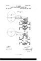
- Figure l shows a vertical section of a valve'as used by me.
- Fig. 2 shows the application of my system in a plant
- Fig. 3 shows by a sectional viewa modication of the valve illustrated in Fig.1.
- valve shown in Fig. l is automatically closed when the pressure increases and opened in the same manner when the pressure decreases. It is provided with a valve K, which can be replaced by a grooved piston or removable diaphragm.
- a counter-weight P, acting upon arm L of the lever F, is heavy enough to overcome the normal pressure of the Water yin the pipe on the vpiston D, which is conlows:
- the plant of water-pipes is madenected by rod R with the arm of the same lever F. This rod also connects said valve and piston.
- the Weight P is so proportioned to the area of piston D as to keep the valve K open under normal pressure; but When the pressure is increased in the pipes it becomes sufficient upon said piston to force valve K to its seat in spite of the pressure of the Weight P, thus cutting off the supply for domestic purposes through the branch in which said Valve is situated.
- the pressure of the Water is decreased to its normal standard, the valve K opens, and the Water Will circulate, as before.
- the pressure ⁇ may be increased in the pipes by pumps or by reservoirs.
- Increased pressure in case of fire may be obtained by a quicker movenient of the pump, (and in this case the plant must be isolated from the reservoir,) or the reservoir is connected with another one oc, located so high as to give sufficient head to close the valves, which are balanced under normal pressure, and to throw the Water in the hydrant to a sufficient height to iightthe tire.
- the length of the line H indicates ⁇ graphically the normal pressure of Water for domestic use, and H the pressure desired in case of iire.
- g g2 g3 show the branch pipes for domestic use
- f ff2 f3 show the hydrants to be used in case of fire.
- the pressure might be reduced to its normal standard, and thus again alloW the delivery of Water for domestic purposes.
- rlhe lever F is provided With a kind of paw] 71 which automatically engages the cover of the valve as the lever rises and keeps the lever in its raised position even when the pressure is diminished. To open the valve, it is sufcient to manually disengage the paWl 7L from the cover.
- Fig. 3 shows another apparatus, the valve of which remains closed even when the pressure decreases and which must be opened by hand.
- the Weight P Under normal pressure the Weight P is sufficiently effective to keep the valve open against the pressure of the Water upon its un- ⁇ counter-seat. If in this case the pressure is reduced to the normal, the larger area of the valve 'acted uponv bythe diminished pressure will still be sufficient to counterpoise the Weight P and the valve Will remain closed.
- valves for normal pressure that springs may be substituted for counter-Weights upon the levers or bearing directly upon the valves.
- springs may be substituted for counter-Weights upon the levers or bearing directly upon the valves.
- These au tomatically-closin g valves may readily be substituted for those ordinarily in use and which are raised and lowered by means of a screw.
- the combination With a reservoir, a main therefrom, fire-hydrants connected with said main, and branch servicepipesof pumps and an auxiliary reservoir for increasing the pressure in said main and automatic self-closing valves in said branch pipes adapted to operate under such increased pressure, substantially as set forth.
Landscapes
- Engineering & Computer Science (AREA)
- Physics & Mathematics (AREA)
- Fluid Mechanics (AREA)
- Mechanical Engineering (AREA)
- General Engineering & Computer Science (AREA)
- Fire-Extinguishing By Fire Departments, And Fire-Extinguishing Equipment And Control Thereof (AREA)
Description
(No Model.)
Y 2 Sheets-Sheet 1.
N. SIMIN. SAFETY WATER CONDUCT AGAINST FIRES.
. Patented Mar. 29, 1892.
A TTOHN E YS 2 sheets-#sheen 2.
(No Moa-e1.)
' Y N. SIMIN.
SAFETY WATER GONDUOT AGAINST FIRES. I No.. 471,699. Patented Mar. 29,1892.
'me ronms paens cu., pHoro-umu., mamma-ran, nA c,
UNTTED STATES PATENT OFFICE.
NICHOLAS SIMIN, OF MOSCOW, RUSSIA.
SAFETY WATER-CONDUCT AGAAINST FIRES.
SPECIFICATION forming part of Letters Application led October 11, 1889. Serial No. 326,702.
ject of the Emperor of Russia, residing at Moscow, Russia, have invented a new and useful System of Water-Works Insuring a Full Supply of Water in Case of Fire, (patented in France July16,1889,No.199,6l5; in Germany July 21, 1889, No. 15,473; in Belgium August 3, 1889, No. 87,250, and in England August 3, '1889, No. 12,870,) of which the following is a full, clear, and exact description, reference being had to the accompanying drawings, which v are hereby made a part of this specification. A system of water-works must answer the following requirements to work eflicaciously in case of lire: First, the Water must constantly and in sufficient quantity flow from thehydrants attached to the pipes; second, the pressure on the water in the pipes must be sufficient to enable it to be used directly in case of iire without necessitating pumps.
The uses and capacity of the works are calculated on the basis of water used for domestic purposes, and it often happens that the entire quantity of wateris used forhousehold requirements. If it is intended to make the plant capable of lighting fire and at the same time supplying water for domestic purposes, it is generally deemed sufcient to enlarge the dimensions of the different parts. Engineers state that the quantity of water flowing from a hydrant for use in case of fire should be at least eight thousand six hundred liters per minute or twelve millions three hund red thousand liters in twenty-four hours. It is obvious that a surplus of this magnitude is not in the reach of all cities and still less available for small towns. If a city has not Waterworks yielding much more than is required for domestic use,none of the present systems can Warrant efficacious workings of the hydrants in case of lire, and pecuniary considerations generally forbid such magnitude of plant. If at a certain time the use of water is small, as during the night, the water in the pipes could be used, though under weak pressure; but if a fire should break out during the day, when the demand for water is greater and even equal to the rcapacity of the plant there would be no water to iight the fire, and the Patent No. 471,699, dated March 29, 1892.
(No model.) Patented in France .Tnly 16, 1889, No, 199,615: in Germany July 2l, 1889, No. 15,473; in Belgium August 3, 1389, No. 87,250,
and in England August 3, 1889, No. 12,370.
consequences might be and have often been found to be disastrous.
My system of water-works insures such a supply of water as is necessary to fight the tire, can be used in cities, villages, factories, and in general in any locality, and is based upon the following principle: In case of fire the distribution of Water for domestic purposes, fountains,&c.,is automatically stopped by means of increase of pressure in the pipes and the entire quantity of water delivered by the pipes is used under a higher pressure to iight the fire. Under this system it is possible to use the water-pipes in case of fire without a considerable increase in the cost of construction.
Another advantage of my system is that the quantity of water for the fire is constant and well-determined and unexpected changes are not to be apprehended.
The arrangement of my system is as folin such a manner that the entire quantity of Water supplied can be directed to any point of the locality where pipes have been laid; second, on the plant of pipes a number of hydrants are erected to be used to fight the lire; third, every domestic-service branch of the pipe is provided with a valve closing automatically, consisting of a grooved piston or a movable diaphragm balanced by means of a piston and a counter-weight, and which allows a free flowing of the water in the branch pipes if the pressure is normal, but which closes and consequently cuts off this ilow as soon as the pressure increases.
In the annexed drawings, Figure l shows a vertical section of a valve'as used by me. Fig. 2 shows the application of my system in a plant, and Fig. 3 shows by a sectional viewa modication of the valve illustrated in Fig.1.
The valve shown in Fig. l is automatically closed when the pressure increases and opened in the same manner when the pressure decreases. It is provided with a valve K, which can be replaced by a grooved piston or removable diaphragm. A counter-weight P, acting upon arm L of the lever F, is heavy enough to overcome the normal pressure of the Water yin the pipe on the vpiston D, which is conlows: First, the plant of water-pipes is madenected by rod R with the arm of the same lever F. This rod also connects said valve and piston. The Weight P is so proportioned to the area of piston D as to keep the valve K open under normal pressure; but When the pressure is increased in the pipes it becomes sufficient upon said piston to force valve K to its seat in spite of the pressure of the Weight P, thus cutting off the supply for domestic purposes through the branch in which said Valve is situated. When the fire is subdued, the pressure of the Water is decreased to its normal standard, the valve K opens, and the Water Will circulate, as before. The pressure `may be increased in the pipes by pumps or by reservoirs. Increased pressure in case of fire may be obtained by a quicker movenient of the pump, (and in this case the plant must be isolated from the reservoir,) or the reservoir is connected with another one oc, located so high as to give sufficient head to close the valves, which are balanced under normal pressure, and to throw the Water in the hydrant to a sufficient height to iightthe tire.
In Fig. 2 the length of the line H indicates `graphically the normal pressure of Water for domestic use, and H the pressure desired in case of iire. g g2 g3 show the branch pipes for domestic use, and f ff2 f3 show the hydrants to be used in case of lire. In case of any pipes being broken or if more hydrants should be opened than is necessary, the pressure might be reduced to its normal standard, and thus again alloW the delivery of Water for domestic purposes. To avoid this diiiiculty, We should place on the branches for domestic or trade uses, especially on such having great delivery-valves, an automatic closing device which does not open again automatically if the pressure diminishes. A simple modification of the valve shown in Fig. 1 will be sufcient for this purpose. rlhe lever F is provided With a kind of paw] 71 Which automatically engages the cover of the valve as the lever rises and keeps the lever in its raised position even when the pressure is diminished. To open the valve, it is sufcient to manually disengage the paWl 7L from the cover.
Fig. 3 shows another apparatus, the valve of which remains closed even when the pressure decreases and which must be opened by hand. Under normal pressure the Weight P is sufficiently effective to keep the valve open against the pressure of the Water upon its un- `counter-seat. If in this case the pressure is reduced to the normal, the larger area of the valve 'acted uponv bythe diminished pressure will still be sufficient to counterpoise the Weight P and the valve Will remain closed.
It is evident for the purposes of balancing the valves for normal pressure that springs may be substituted for counter-Weights upon the levers or bearing directly upon the valves. These au tomatically-closin g valves may readily be substituted for those ordinarily in use and which are raised and lowered by means of a screw.
Having thus described my invention, What I claim as new, and desire to secure by Letters Patent, is-
In water-Works, the combination, With a reservoir, a main therefrom, lire-hydrants connected with said main, and branch servicepipesof pumps and an auxiliary reservoir for increasing the pressure in said main and automatic self-closing valves in said branch pipes adapted to operate under such increased pressure, substantially as set forth.
In testimony whereof I have signed my name to this specification in the presence of tWo subscribing Witnesses.
NICHOLAS SIMIN.
Witnesses:
S. LAMINE, M. LEvINsKY.
Publications (1)
| Publication Number | Publication Date |
|---|---|
| US471699A true US471699A (en) | 1892-03-29 |
Family
ID=2540558
Family Applications (1)
| Application Number | Title | Priority Date | Filing Date |
|---|---|---|---|
| US471699D Expired - Lifetime US471699A (en) | Nicholas simin |
Country Status (1)
| Country | Link |
|---|---|
| US (1) | US471699A (en) |
Cited By (1)
| Publication number | Priority date | Publication date | Assignee | Title |
|---|---|---|---|---|
| US20100079059A1 (en) * | 2006-04-18 | 2010-04-01 | John Roberts | Solid State Lighting Devices Including Light Mixtures |
-
0
- US US471699D patent/US471699A/en not_active Expired - Lifetime
Cited By (1)
| Publication number | Priority date | Publication date | Assignee | Title |
|---|---|---|---|---|
| US20100079059A1 (en) * | 2006-04-18 | 2010-04-01 | John Roberts | Solid State Lighting Devices Including Light Mixtures |
Similar Documents
| Publication | Publication Date | Title |
|---|---|---|
| US471699A (en) | Nicholas simin | |
| US412789A (en) | probert | |
| US589124A (en) | Place | |
| US1015464A (en) | Water-supply system. | |
| US798551A (en) | Combination-valve. | |
| US135976A (en) | Improvement in cut-offs for fire-plug systems | |
| US929852A (en) | Fluid-distributing system. | |
| US266484A (en) | Tolbeet lajfstqn | |
| US1304529A (en) | Water-supply system | |
| US696135A (en) | Faucet. | |
| US440100A (en) | Automatic valve | |
| US920774A (en) | Water-supply system. | |
| US623773A (en) | Water-pressure regulator | |
| US415212A (en) | Water system for protecting buildings against fire | |
| US1186147A (en) | Automatic gas-shut-off valve. | |
| US584799A (en) | Half to e | |
| US134348A (en) | Improvement in valves for hydraulic mains | |
| US939310A (en) | Attachment for feed-water injectors. | |
| US815691A (en) | Automatic feed device. | |
| US90371A (en) | Improvement in steam-engine lubricators | |
| US630860A (en) | Apparatus for automatically insuring periodic operation of stationary fire-pumps. | |
| US733962A (en) | Automatic fire-extinguisher. | |
| US192487A (en) | Improvement in apparatus for automatically reducing or regulating fluid-pressure | |
| US863900A (en) | Apparatus for regulating pressure in pipes. | |
| US994255A (en) | Automatic sprinkler system. |