US4717031A - Fermentation vessel - Google Patents
Fermentation vessel Download PDFInfo
- Publication number
- US4717031A US4717031A US06/856,742 US85674286A US4717031A US 4717031 A US4717031 A US 4717031A US 85674286 A US85674286 A US 85674286A US 4717031 A US4717031 A US 4717031A
- Authority
- US
- United States
- Prior art keywords
- fermentation vessel
- closure member
- container
- neck portion
- body portion
- Prior art date
- Legal status (The legal status is an assumption and is not a legal conclusion. Google has not performed a legal analysis and makes no representation as to the accuracy of the status listed.)
- Expired - Fee Related
Links
- 238000000855 fermentation Methods 0.000 title claims abstract description 58
- 230000004151 fermentation Effects 0.000 title claims abstract description 58
- 239000007788 liquid Substances 0.000 claims description 19
- 238000010438 heat treatment Methods 0.000 claims description 7
- 238000000926 separation method Methods 0.000 claims description 3
- 238000007789 sealing Methods 0.000 claims 1
- 238000000071 blow moulding Methods 0.000 abstract description 6
- 239000013049 sediment Substances 0.000 description 7
- CURLTUGMZLYLDI-UHFFFAOYSA-N Carbon dioxide Chemical compound O=C=O CURLTUGMZLYLDI-UHFFFAOYSA-N 0.000 description 6
- 239000000463 material Substances 0.000 description 4
- 238000000034 method Methods 0.000 description 4
- 239000004033 plastic Substances 0.000 description 4
- 229920003023 plastic Polymers 0.000 description 4
- -1 polyethylene Polymers 0.000 description 4
- 235000013405 beer Nutrition 0.000 description 3
- 229910002092 carbon dioxide Inorganic materials 0.000 description 3
- 239000001569 carbon dioxide Substances 0.000 description 3
- XLYOFNOQVPJJNP-UHFFFAOYSA-N water Substances O XLYOFNOQVPJJNP-UHFFFAOYSA-N 0.000 description 3
- 239000004698 Polyethylene Substances 0.000 description 2
- 239000004743 Polypropylene Substances 0.000 description 2
- 235000013361 beverage Nutrition 0.000 description 2
- 230000000694 effects Effects 0.000 description 2
- 239000012530 fluid Substances 0.000 description 2
- 238000004519 manufacturing process Methods 0.000 description 2
- 229920000573 polyethylene Polymers 0.000 description 2
- 229920001155 polypropylene Polymers 0.000 description 2
- 235000013334 alcoholic beverage Nutrition 0.000 description 1
- 238000011109 contamination Methods 0.000 description 1
- 239000007789 gas Substances 0.000 description 1
- 239000011521 glass Substances 0.000 description 1
- 239000004615 ingredient Substances 0.000 description 1
- 239000004579 marble Substances 0.000 description 1
- 230000013011 mating Effects 0.000 description 1
- 239000000203 mixture Substances 0.000 description 1
- 238000000465 moulding Methods 0.000 description 1
Images


Classifications
-
- C—CHEMISTRY; METALLURGY
- C12—BIOCHEMISTRY; BEER; SPIRITS; WINE; VINEGAR; MICROBIOLOGY; ENZYMOLOGY; MUTATION OR GENETIC ENGINEERING
- C12C—BEER; PREPARATION OF BEER BY FERMENTATION; PREPARATION OF MALT FOR MAKING BEER; PREPARATION OF HOPS FOR MAKING BEER
- C12C11/00—Fermentation processes for beer
- C12C11/003—Fermentation of beerwort
-
- C—CHEMISTRY; METALLURGY
- C12—BIOCHEMISTRY; BEER; SPIRITS; WINE; VINEGAR; MICROBIOLOGY; ENZYMOLOGY; MUTATION OR GENETIC ENGINEERING
- C12C—BEER; PREPARATION OF BEER BY FERMENTATION; PREPARATION OF MALT FOR MAKING BEER; PREPARATION OF HOPS FOR MAKING BEER
- C12C13/00—Brewing devices, not covered by a single group of C12C1/00 - C12C12/04
- C12C13/10—Home brew equipment
-
- C—CHEMISTRY; METALLURGY
- C12—BIOCHEMISTRY; BEER; SPIRITS; WINE; VINEGAR; MICROBIOLOGY; ENZYMOLOGY; MUTATION OR GENETIC ENGINEERING
- C12G—WINE; PREPARATION THEREOF; ALCOHOLIC BEVERAGES; PREPARATION OF ALCOHOLIC BEVERAGES NOT PROVIDED FOR IN SUBCLASSES C12C OR C12H
- C12G1/00—Preparation of wine or sparkling wine
- C12G1/02—Preparation of must from grapes; Must treatment and fermentation
- C12G1/0206—Preparation of must from grapes; Must treatment and fermentation using a home wine making vessel
-
- C—CHEMISTRY; METALLURGY
- C12—BIOCHEMISTRY; BEER; SPIRITS; WINE; VINEGAR; MICROBIOLOGY; ENZYMOLOGY; MUTATION OR GENETIC ENGINEERING
- C12L—PITCHING OR DEPITCHING MACHINES; CELLAR TOOLS
- C12L9/00—Venting devices for casks, barrels, or the like
-
- Y—GENERAL TAGGING OF NEW TECHNOLOGICAL DEVELOPMENTS; GENERAL TAGGING OF CROSS-SECTIONAL TECHNOLOGIES SPANNING OVER SEVERAL SECTIONS OF THE IPC; TECHNICAL SUBJECTS COVERED BY FORMER USPC CROSS-REFERENCE ART COLLECTIONS [XRACs] AND DIGESTS
- Y10—TECHNICAL SUBJECTS COVERED BY FORMER USPC
- Y10S—TECHNICAL SUBJECTS COVERED BY FORMER USPC CROSS-REFERENCE ART COLLECTIONS [XRACs] AND DIGESTS
- Y10S215/00—Bottles and jars
- Y10S215/902—Vent
Definitions
- This invention relates to a fermentation vessel.
- This invention more particularly relates to a fermentation vessel, which is molded in plastic and is intended for domestic use.
- a further disadvantage of known domestic brewing techniques is that they require the liquid to be fermented in a first vessel, and then transferred to a second vessel.
- One reason for this is to separate sediment generated during the initial fermentation. Then, a second fermentation is carried out in the second vessel. Frequently, it is then necessary to transfer the fermented liquid from the second vessel into bottles. It is to be appreciated that this requires numerous individual steps, all of which must be carried out with carefully cleaned equipment, to prevent growth of unwanted organisms etc.
- conventionally much of the equipment used is in the form of simple containers, without taps etc. As a result, the transference of liquid from one vessel to another has to be carried out by siphoning the liquid from one vessel to the other.
- the fermentation vessel should incorporate as few components as possible, to facilitate both manufacture and use. Further, the fermentation vessel should be suitable for a single stage fermentation, in the one vessel. It should also facilitate the transferring of the fermented liquid from the vessel.
- a unitary, molded fermentation vessel comprising: a container for receiving liquid, and including and a neck portion at its upper end; and a closure member, which includes an air lock means and a connection portion, and which is removable in use, the closure member being adapted, in use, after separation from the connection portion, for forming a seal with the neck portion.
- a closure member including an air lock is molded simultaneously with the container itself.
- a connection portion is removed from the closure member.
- one of the neck portion and the closure member is provided with an O-ring seal, which engages a correspondingly machined seat of the other of the closure member and the neck portion.
- the present invention thus also provides a fermentation vessel having two principal components, namely a container and a closure member, which have been molded together and then separated.
- the closure member includes the air lock.
- a method for forming a fermentation vessel as defined above comprising the steps of:
- the fermentation vessel advantageously includes other features, to facilitate its use as a single stage fermentation vessel.
- it can include an outlet tap, mounted in a socket near the base of the container.
- This outlet tap can be connected by a flexible pipe to a float within the container. This enables the outlet tap always to draw off fluid from near the top of fluid within the container. This should assist in preventing sediment from being drawn off accidentally.
- the base of the container it is preferred for the base of the container to be shaped, to both facilitate collection of sediment and to withstand pressure.
- the base can have two coplanar flat parts for supporting the container, and a curved surface extending from one side of the container to the other between the flat parts.
- the interior of the container will have a similar profile to the exterior.
- Sediment should then preferentially settle on the flat parts, rather than the raised parts of the curved surface. Also, it has been found that the provision of such a curved surface restrains the base, if the container is pressurized to low pressures, i.e. pressures less than one atmosphere above atmospheric pressure. A common problem with flat bottomed containers is that they bulge outwards under pressure, possibly making the container unstable. It has been found that this curved surface prevents this bulging effect under such moderate pressures.
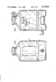
- FIG. 1 shows a perspective view from above of a unitary fermentation vessel
- FIG. 2 is an elevational view of the upper part of the fermentation vessel of FIG. 1, with a closure member removed;
- FIG. 3 is an elevational view of the upper part of the fermentation vessel of FIGS. 1 and 2, in partial section, with a detached closure member;
- FIG. 4 is an elevational view of the upper part of the fermentation vessel, in partial section, showing a closure cap
- FIG. 5 is a perspective view from below of a fermentation vessel with detached closure member
- FIGS. 6 and 7 are elevational views of the fermentation vessel of FIG. 5, with FIG. 7 being partly in section.
- the fermentation vessel 1 comprises a container 2, which includes a neck portion 3.
- the fermentation vessel also has a closure member 4, which includes an air lock 5 and a connection portion 6 (see FIG. 2).
- the container 2 has a generally cylindrical outer wall 10. At its base, the container 2 includes two flat portions 11, 12 (see FIG. 5) for supporting the fermentation vessel 1. Between the flat portions 11, 12, there extends a curved portion 14, of generally uniform width. As indicated in the drawings, the various portions 11, 12 and 14, and the outer cylindrical side wall 10 blend smoothly into one another.
- the socket 16 Adjacent the base of the container 2, there is a socket 16 for a tap 18.
- the socket 16 has a raised boss, which has a vertical surface, and a threaded socket for the tap 18.
- each recess 22 Adjacent the top of the cylindrical outer wall 10, there are two generally rectangular recesses 22, which are diametrically opposite one another, above the ends of the curved portion 14. Each recess 22 is generally rectangular, and defines a gripping surface 24, by which the vessel 1 can be lifted.
- the neck portion 3 is connected to the cylindrical outer wall 10 by a conical surface 26, in known manner.
- the neck portion 3 is generally cylindrical, and is best seen in FIG. 2.
- the neck portion 3 includes an outwardly facing annular groove 28.
- the groove 28 is formed between an upper shoulder 30 of the conical surface 26, forming a flat surface, and an outwardly extending annular lip 32.
- the lip 32 does not extend out as far as the shoulder 30.
- the thread 34 is a buttress thread.
- the thread 34 is formed on a cylindrical part of the neck portion 3.
- the outside diameter of the screw thread 34 corresponds to that of the lip 32.
- the closure member 4 has a generally cylindrical body portion 40, which is closed at the top by a shallow, conical top surface 42.
- a part 44 of the body portion 40 is also cylindrical, but of smaller diameter, so as to be radially inset from the main part of the cylindrical body portion 40.
- This part 44 is joined to adjacent parts of the body portion 40 by frustro-conical sections 46. As shown in FIG. 3, the part 44 then defines a generally cylindrical closure surface 48, on its inside.
- the body portion 40 is continuous with the connection portion 6.
- the connection portion 6 comprises an upper frustro-conical part 50 and a short cylindrical part 52.
- the cylindrical part 52 is continuous with the neck portion 3 and is of the same diameter.
- the air lock 5 is a generally U-shape duct 54.
- the duct 54 has a generally rectangular cross-section along most of its length. One end of the duct 54 opens into the body portion 40.
- the other end of the duct 54 includes an enlarged part 56, which is part-spherical on either side. This enlarged part 56 continues into a narrow, cylindrical end part 58.
- Web sections 60, 61 extend between the two limbs of the U-shape duct 54 and between the duct 54 and the body portion 40.
- the fermentation vessel 1 is formed by blow molding, in known manner.
- the vessel 1 is formed in a single mold, with a dividing plane of the mold extending vertically through the vessel 1 and through the air lock 5 and socket 16.
- a threaded insert is provided for the socket 16.
- the vessel 1 is dimensioned, to enable it to be used for brewing five gallons (imperial) of liquid.
- the wall thickness of the vessel 1 will be in the range 90-180 thousandths of an inch.
- blow molding will result in a continuous surface.
- the end of the cylindrical portion 58 of the air lock 5 will be closed, as indicated at 60.
- the vessel 1 can be molded in any suitable plastics material, such as polyethylene or polypropylene. Further, the plastic can be transparent, translucent or coloured, as detailed below.
- FIG. 1 shows the fermentation vessel 1, as blow-molded in one piece.
- the closure member 4 is separated from the container 2. They are separated along a plane indicated by the dotted line 62 in FIG. 2. Then, the connection portion 6 of the closure member 4 has to be removed and discarded. The closure member 4 and connection portion 6 are correspondingly separated along a plane indicated by the dotted line 64 in FIG. 2. Also, the closed end 60 of the air lock 5 is cut off and discarded, to leave the duct 54 open at one end.
- the closure member 4 has to form a good seal with the container 2. Consequently, after separation of the closure member 4, the closure surface 48 is machined to form an accurate cylindrical closure surface; the blow molding process does not result in a sufficiently accurate surface. Then, an O-ring 66 is fitted into the annular groove 28, as shown in FIG. 3. The closure member 4 can then be slid down over the neck portion 3, until the closure surface 48 contacts the O-ring 66. The frustro-conical parts 46 enable the closure surface 48 to engage the O-ring 66 smoothly. Then, as shown in FIG. 3, the closure member 4 rests on the container 2, so that the interior of the container is only open to the atmosphere via the air lock 5.
- the profile of the socket and a screw thread are formed by the molding operation. However, again the base of the socket will be closed by the material of the container. Thus, this is cut or drilled away, to open the socket 16. The tap 18 can then be fitted.
- the fermentation vessel 1 is then ready for use, and this is described below.
- the user In use, with the tap 18 and O-ring 66 fitted to the container 2, the user has essentially two components to handle, namely the container 2 and closure member 4. To brew beer or wine, the necessary ingredients are prepared, and the container 2 is filled with them.
- the air lock 5 is then filled with a suitable amount of water for forming an air lock, as shown in FIG. 3, and indicated at 68.
- the closure member 4 is then placed on the container 2, with a seal being formed between it and the O-ring 66.
- the vessel 1 can then be left at a suitable location, whilst the fermentation proceeds. Gases given off by fermentation are discharged through the air lock 5, in known manner.
- an elongate heating element can be placed around the container 2.
- a heating element is shown in FIG. 5 and denoted by the reference 70. It is located in the annular recess 20.
- the heating element 70 is an electrical resistance heater, and encircles the container 2, as a belt.
- the annular recess 20 ensures that the heating element 70 is secured in position, and will not slide off the container 2.
- the profile of the base is such as to assist in the collection of sediment, so that it does not contaminate liquid drawn off from the container 2. The user can then draw off liquid through the tap 18, as required.
- the tap 18 can be arranged to draw off liquid from near the upper end of the container 2. Such an arrangement is shown in FIG. 6.
- a flexible pipe 70 is connected at one end to the tap 18, and at the other end to a float 72.
- the free end of the pipe 70 is always held near the liquid surface 73. This enables liquid to be drawn off through the tap 18, which does not include any sediment, which has fallen towards the bottom of the container 2.
- the closure member 4 can be left in position.
- the air lock 5 would then still operate as an air lock, but in reverse.
- air would pass through the air lock 5 into the container, to replace removed liquid.
- the water in the air lock 5 however would still maintain a seal.
- the cap is denoted by the reference 74, and includes a thread engaging the screw thread 34.
- the cap 74 includes ribs for gripping it. It also includes a resilient planar gasket 76. Where a cap 74 is to be used, then the top of the neck portion 3 is machined, after the closure member 4 is cut away. This provides a smooth surface on the neck portion 3, suitable for mating with the gasket 76.
- the screw cap 74 can then provide a good seal for beer, wine etc. in the container 2.
- the vessel 1 can be fitted with a screw cap, comparable to the cap 74, but including an inlet for carbon dioxide. This inlet is then connected to a suitable source of carbon dioxide at the required pressure. This then enables the product to be kept in a carbonated condition, ready for dispensing. It has been found that the fermentation vessel can take moderate pressures above atmospheric pressure, e.g. pressures such as 8 psi.
- the shape of the curved portion 14 assists when the container 2 is pressurized. The curved portion 14 prevents the base doming outwards, as is common for flat bottom containers.
- the vessel 1 can include other features, such as a shallow recess 80, for a label or the like.
- the vessel 1 Whilst the vessel 1 is intended for a single stage fermentation, it can still be used in other fermentation methods, where the fermented product is transferred to another vessel. In particular, the finished product can be transferred to bottles, for storage.
- the material of the vessel 1 can have a variety of finishes. It can be either transparent or translucent. Further, it could be "touch clear”. Such a material is translucent until wetted on one side, when it becomes transparent.
- the plastic used can also be given a colour tint. This can either be uniform, or it can deliberately be nonuniform or streaked to give a marble finish. Thus, polypropylene could be streaked with a blue colour. For polyethylene, it has been found more effective to use a brown colour.
Landscapes
- Chemical & Material Sciences (AREA)
- Organic Chemistry (AREA)
- Engineering & Computer Science (AREA)
- Health & Medical Sciences (AREA)
- Biochemistry (AREA)
- Bioinformatics & Cheminformatics (AREA)
- General Engineering & Computer Science (AREA)
- General Health & Medical Sciences (AREA)
- Genetics & Genomics (AREA)
- Life Sciences & Earth Sciences (AREA)
- Wood Science & Technology (AREA)
- Zoology (AREA)
- Food Science & Technology (AREA)
- Apparatus Associated With Microorganisms And Enzymes (AREA)
- Closures For Containers (AREA)
Applications Claiming Priority (1)
| Application Number | Priority Date | Filing Date | Title |
|---|---|---|---|
| CA000494315A CA1236040A (fr) | 1985-10-31 | 1985-10-31 | Cuve de fermentation |
Publications (1)
| Publication Number | Publication Date |
|---|---|
| US4717031A true US4717031A (en) | 1988-01-05 |
Family
ID=4131768
Family Applications (1)
| Application Number | Title | Priority Date | Filing Date |
|---|---|---|---|
| US06/856,742 Expired - Fee Related US4717031A (en) | 1985-10-31 | 1986-04-28 | Fermentation vessel |
Country Status (3)
| Country | Link |
|---|---|
| US (1) | US4717031A (fr) |
| CA (1) | CA1236040A (fr) |
| GB (1) | GB2184714B (fr) |
Cited By (44)
| Publication number | Priority date | Publication date | Assignee | Title |
|---|---|---|---|---|
| USD303496S (en) | 1986-09-11 | 1989-09-19 | Bmr Investments, Inc. | Bottle |
| USD303497S (en) | 1987-06-01 | 1989-09-19 | Bmr Investments, Inc. | Bottle |
| USD308794S (en) | 1987-02-26 | 1990-06-26 | Bmr Investments, Inc. | Combined water dispenser and container |
| USD309231S (en) | 1987-03-02 | 1990-07-17 | Bmr Investments, Inc. | Combined water dispenser and container |
| USD324650S (en) | 1989-05-17 | 1992-03-17 | BMR, Inc. | Bottle |
| US5423447A (en) * | 1993-09-10 | 1995-06-13 | Advanced Polymer Technology, Inc. | Adjustable water-tight sump |
| USD383763S (en) * | 1996-06-13 | 1997-09-16 | Advanced Polymer Technology, Inc. | Combined one-piece tank sump with integral dust cover |
| US5722556A (en) * | 1993-09-28 | 1998-03-03 | Nippondenso Co., Ltd. | Reserve tank cap having easily manufactured integral overflow passage and reserve tank |
| WO1998030456A1 (fr) * | 1997-01-06 | 1998-07-16 | Yuhl Whang | Recipient pour stocker du kimchi |
| US5833392A (en) * | 1996-06-11 | 1998-11-10 | Advanced Polymer Technology, Inc. | One-piece tank sump with integral dust cover |
| US6079751A (en) * | 1996-07-11 | 2000-06-27 | Advanced Polymer Technology, Inc. | Flexible entry boot assembly for use with a fluid containment region |
| USD430987S (en) * | 1998-01-29 | 2000-09-19 | Emerson Electric Co. | Food waste disposer |
| USD431153S (en) * | 1998-01-29 | 2000-09-26 | Emerson Electric Co. | Food waste disposer |
| USD431752S (en) * | 1998-01-29 | 2000-10-10 | Emerson Electric Co. | Food waste disposer |
| WO2001012510A1 (fr) * | 1999-08-18 | 2001-02-22 | Datograf Apparatebau Gmbh & Co. | Recipient en plastique |
| USD451029S1 (en) | 2000-04-05 | 2001-11-27 | Agilent Technologies, Inc. | Container for liquids |
| USD454467S1 (en) | 2000-06-16 | 2002-03-19 | Heineken Technical Services B.V. | Drink dispensing apparatus |
| US20030102339A1 (en) * | 2001-12-05 | 2003-06-05 | Masterchem Industries, Inc. | Container |
| US6612620B1 (en) | 1996-07-11 | 2003-09-02 | Advanced Polymer Technology, Inc. | Flexible entry boot |
| US20040086609A1 (en) * | 2002-11-06 | 2004-05-06 | Pazik Andre J | Anaerobic fermentation method and apparatus |
| WO2007052856A1 (fr) * | 2005-11-02 | 2007-05-10 | Industry Academy Cooperation Group Of Korea National Agricultural College | Sas pour fermentation sûre de type à chute naturelle |
| US20080308522A1 (en) * | 2007-05-11 | 2008-12-18 | Alcan Global Pharmaceutical Packaging Inc. | Easy grip bottle |
| USD607336S1 (en) * | 2007-03-30 | 2010-01-05 | The Procter & Gamble Company | Container |
| USD654302S1 (en) * | 2010-04-27 | 2012-02-21 | Niro Plan Ag | Waste disposer |
| USD684004S1 (en) * | 2011-12-21 | 2013-06-11 | Emerson Electric Co. | Food waste disposer |
| USD684003S1 (en) * | 2011-12-21 | 2013-06-11 | Emerson Electric Co. | Food waste disposer |
| USD684005S1 (en) * | 2011-12-21 | 2013-06-11 | Emerson Electric Co. | Food waste disposer |
| US8876087B1 (en) * | 2011-10-13 | 2014-11-04 | William M. Lake | Water tank system |
| US20150128810A1 (en) * | 2013-11-08 | 2015-05-14 | Deep Wood Brew Products, LLC | Mini-keg growler |
| US20150128809A1 (en) * | 2013-11-08 | 2015-05-14 | Northern Brewer Llc | Home beer brewing carboy |
| US20150203800A1 (en) * | 2014-01-22 | 2015-07-23 | Northern Brewer Llc | Modular keg for home brewing |
| USD746100S1 (en) | 2014-08-25 | 2015-12-29 | Emerson Electric Co. | Food waste disposer |
| USD753432S1 (en) | 2015-01-12 | 2016-04-12 | Emerson Electric Co. | Food waste disposer |
| USD753433S1 (en) | 2015-01-12 | 2016-04-12 | Emerson Electric Co. | Food waste disposer |
| USD759423S1 (en) | 2015-01-12 | 2016-06-21 | Emerson Electric Co. | Food waste disposer |
| USD769060S1 (en) * | 2014-12-08 | 2016-10-18 | Eric Klein | Vegetable fermenting kitchenware |
| USD772005S1 (en) * | 2014-12-23 | 2016-11-22 | Bare Escentuals Beauty, Inc. | Container |
| USD787266S1 (en) * | 2014-07-31 | 2017-05-23 | GrowlerWerks, INC. | Dimpled beverage dispenser |
| USD810498S1 (en) * | 2016-02-04 | 2018-02-20 | Craft A Brew | Fermenter |
| USD822422S1 (en) * | 2017-03-21 | 2018-07-10 | Rupert Buchanan | Water cooler bottle with spout |
| USD822426S1 (en) | 2016-06-27 | 2018-07-10 | Emerson Electric Co. | Food waste disposer |
| US10968419B1 (en) | 2017-05-07 | 2021-04-06 | Douglas J. Lanning | Fermentation byproduct management |
| US11124749B2 (en) * | 2018-11-01 | 2021-09-21 | Lg Electronics Inc. | Beverage maker |
| USD934622S1 (en) | 2019-11-15 | 2021-11-02 | Karen Wang Diggs | Fermentation kitchenware |
Families Citing this family (2)
| Publication number | Priority date | Publication date | Assignee | Title |
|---|---|---|---|---|
| RU2216447C1 (ru) * | 2002-12-05 | 2003-11-20 | Закрытое акционерное общество "Бородино" | Способ изготовления полых изделий из пластмассы |
| GB2572153B (en) * | 2018-03-19 | 2022-06-08 | Victors Drinks Ltd | Fermentation vessel |
Citations (6)
| Publication number | Priority date | Publication date | Assignee | Title |
|---|---|---|---|---|
| US4055282A (en) * | 1976-04-19 | 1977-10-25 | Automatic Liquid Packaging, Inc. | Container with one-piece neck and discharge controller |
| US4113129A (en) * | 1978-01-05 | 1978-09-12 | Respiratory Care, Inc. | Container for sterile liquids |
| US4176755A (en) * | 1979-01-26 | 1979-12-04 | Baxter Travenol Laboratories, Inc. | Resealable pour bottle with severing ring |
| US4378891A (en) * | 1981-09-29 | 1983-04-05 | Baxter Travenol Laboratories, Inc. | Bottle closure |
| US4478342A (en) * | 1983-07-14 | 1984-10-23 | Baxter Travenol Laboratories, Inc. | Sterilizable container with inner closure and collapse-resistant cover |
| US4579260A (en) * | 1984-02-13 | 1986-04-01 | Plastipak Packaging, Inc. | Plastic blow-molded container having dispensing valve |
-
1985
- 1985-10-31 CA CA000494315A patent/CA1236040A/fr not_active Expired
-
1986
- 1986-04-28 US US06/856,742 patent/US4717031A/en not_active Expired - Fee Related
- 1986-05-20 GB GB8612279A patent/GB2184714B/en not_active Expired
Patent Citations (6)
| Publication number | Priority date | Publication date | Assignee | Title |
|---|---|---|---|---|
| US4055282A (en) * | 1976-04-19 | 1977-10-25 | Automatic Liquid Packaging, Inc. | Container with one-piece neck and discharge controller |
| US4113129A (en) * | 1978-01-05 | 1978-09-12 | Respiratory Care, Inc. | Container for sterile liquids |
| US4176755A (en) * | 1979-01-26 | 1979-12-04 | Baxter Travenol Laboratories, Inc. | Resealable pour bottle with severing ring |
| US4378891A (en) * | 1981-09-29 | 1983-04-05 | Baxter Travenol Laboratories, Inc. | Bottle closure |
| US4478342A (en) * | 1983-07-14 | 1984-10-23 | Baxter Travenol Laboratories, Inc. | Sterilizable container with inner closure and collapse-resistant cover |
| US4579260A (en) * | 1984-02-13 | 1986-04-01 | Plastipak Packaging, Inc. | Plastic blow-molded container having dispensing valve |
Cited By (55)
| Publication number | Priority date | Publication date | Assignee | Title |
|---|---|---|---|---|
| USD303496S (en) | 1986-09-11 | 1989-09-19 | Bmr Investments, Inc. | Bottle |
| USD308794S (en) | 1987-02-26 | 1990-06-26 | Bmr Investments, Inc. | Combined water dispenser and container |
| USD309231S (en) | 1987-03-02 | 1990-07-17 | Bmr Investments, Inc. | Combined water dispenser and container |
| USD303497S (en) | 1987-06-01 | 1989-09-19 | Bmr Investments, Inc. | Bottle |
| USD324650S (en) | 1989-05-17 | 1992-03-17 | BMR, Inc. | Bottle |
| US5423447A (en) * | 1993-09-10 | 1995-06-13 | Advanced Polymer Technology, Inc. | Adjustable water-tight sump |
| US5722556A (en) * | 1993-09-28 | 1998-03-03 | Nippondenso Co., Ltd. | Reserve tank cap having easily manufactured integral overflow passage and reserve tank |
| US5833392A (en) * | 1996-06-11 | 1998-11-10 | Advanced Polymer Technology, Inc. | One-piece tank sump with integral dust cover |
| US5988944A (en) * | 1996-06-11 | 1999-11-23 | Advanced Polymer Technology, Inc. | One-piece tank sump with integral dust cover |
| USD383763S (en) * | 1996-06-13 | 1997-09-16 | Advanced Polymer Technology, Inc. | Combined one-piece tank sump with integral dust cover |
| US6612620B1 (en) | 1996-07-11 | 2003-09-02 | Advanced Polymer Technology, Inc. | Flexible entry boot |
| US6079751A (en) * | 1996-07-11 | 2000-06-27 | Advanced Polymer Technology, Inc. | Flexible entry boot assembly for use with a fluid containment region |
| WO1998030456A1 (fr) * | 1997-01-06 | 1998-07-16 | Yuhl Whang | Recipient pour stocker du kimchi |
| USD430987S (en) * | 1998-01-29 | 2000-09-19 | Emerson Electric Co. | Food waste disposer |
| USD431752S (en) * | 1998-01-29 | 2000-10-10 | Emerson Electric Co. | Food waste disposer |
| USD431153S (en) * | 1998-01-29 | 2000-09-26 | Emerson Electric Co. | Food waste disposer |
| WO2001012510A1 (fr) * | 1999-08-18 | 2001-02-22 | Datograf Apparatebau Gmbh & Co. | Recipient en plastique |
| USD451029S1 (en) | 2000-04-05 | 2001-11-27 | Agilent Technologies, Inc. | Container for liquids |
| USD454467S1 (en) | 2000-06-16 | 2002-03-19 | Heineken Technical Services B.V. | Drink dispensing apparatus |
| US20030102339A1 (en) * | 2001-12-05 | 2003-06-05 | Masterchem Industries, Inc. | Container |
| US7014078B2 (en) * | 2001-12-05 | 2006-03-21 | Masterchem Industries Llc | Container |
| US20040086609A1 (en) * | 2002-11-06 | 2004-05-06 | Pazik Andre J | Anaerobic fermentation method and apparatus |
| US20040086608A1 (en) * | 2002-11-06 | 2004-05-06 | Pazik Andre J. | Anaerobic fermentation method and apparatus |
| US6814992B2 (en) | 2002-11-06 | 2004-11-09 | Andre J. Pazik | Anaerobic fermentation method and apparatus |
| WO2007052856A1 (fr) * | 2005-11-02 | 2007-05-10 | Industry Academy Cooperation Group Of Korea National Agricultural College | Sas pour fermentation sûre de type à chute naturelle |
| USD607336S1 (en) * | 2007-03-30 | 2010-01-05 | The Procter & Gamble Company | Container |
| US20080308522A1 (en) * | 2007-05-11 | 2008-12-18 | Alcan Global Pharmaceutical Packaging Inc. | Easy grip bottle |
| USD654302S1 (en) * | 2010-04-27 | 2012-02-21 | Niro Plan Ag | Waste disposer |
| US8876087B1 (en) * | 2011-10-13 | 2014-11-04 | William M. Lake | Water tank system |
| USD684004S1 (en) * | 2011-12-21 | 2013-06-11 | Emerson Electric Co. | Food waste disposer |
| USD684003S1 (en) * | 2011-12-21 | 2013-06-11 | Emerson Electric Co. | Food waste disposer |
| USD684005S1 (en) * | 2011-12-21 | 2013-06-11 | Emerson Electric Co. | Food waste disposer |
| US9428720B2 (en) * | 2013-11-08 | 2016-08-30 | Deep Wood Brew Products, LLC | Mini-keg growler |
| US20150128810A1 (en) * | 2013-11-08 | 2015-05-14 | Deep Wood Brew Products, LLC | Mini-keg growler |
| US20150128809A1 (en) * | 2013-11-08 | 2015-05-14 | Northern Brewer Llc | Home beer brewing carboy |
| US20160362648A1 (en) * | 2013-11-08 | 2016-12-15 | Deep Wood Brew Products, LLC | Mini-keg growler |
| US20150203800A1 (en) * | 2014-01-22 | 2015-07-23 | Northern Brewer Llc | Modular keg for home brewing |
| USD836978S1 (en) | 2014-07-31 | 2019-01-01 | GrowlerWerks, INC. | Beverage dispenser with sight glass |
| USD787266S1 (en) * | 2014-07-31 | 2017-05-23 | GrowlerWerks, INC. | Dimpled beverage dispenser |
| USD1018194S1 (en) | 2014-07-31 | 2024-03-19 | Perfectwerks Solutions Inc. | Beverage dispenser cap |
| USD904100S1 (en) * | 2014-07-31 | 2020-12-08 | GrowlerWerks, INC. | Beverage dispenser with handle |
| USD746100S1 (en) | 2014-08-25 | 2015-12-29 | Emerson Electric Co. | Food waste disposer |
| USD769060S1 (en) * | 2014-12-08 | 2016-10-18 | Eric Klein | Vegetable fermenting kitchenware |
| USD772005S1 (en) * | 2014-12-23 | 2016-11-22 | Bare Escentuals Beauty, Inc. | Container |
| USD753432S1 (en) | 2015-01-12 | 2016-04-12 | Emerson Electric Co. | Food waste disposer |
| USD780505S1 (en) | 2015-01-12 | 2017-03-07 | Emerson Electric Co. | Food waste disposer |
| USD759423S1 (en) | 2015-01-12 | 2016-06-21 | Emerson Electric Co. | Food waste disposer |
| USD753433S1 (en) | 2015-01-12 | 2016-04-12 | Emerson Electric Co. | Food waste disposer |
| USD810498S1 (en) * | 2016-02-04 | 2018-02-20 | Craft A Brew | Fermenter |
| USD822426S1 (en) | 2016-06-27 | 2018-07-10 | Emerson Electric Co. | Food waste disposer |
| USD853175S1 (en) | 2016-06-27 | 2019-07-09 | Emerson Electric Co. | Food waste disposer |
| USD822422S1 (en) * | 2017-03-21 | 2018-07-10 | Rupert Buchanan | Water cooler bottle with spout |
| US10968419B1 (en) | 2017-05-07 | 2021-04-06 | Douglas J. Lanning | Fermentation byproduct management |
| US11124749B2 (en) * | 2018-11-01 | 2021-09-21 | Lg Electronics Inc. | Beverage maker |
| USD934622S1 (en) | 2019-11-15 | 2021-11-02 | Karen Wang Diggs | Fermentation kitchenware |
Also Published As
| Publication number | Publication date |
|---|---|
| GB2184714A (en) | 1987-07-01 |
| GB2184714B (en) | 1989-10-18 |
| CA1236040A (fr) | 1988-05-03 |
| GB8612279D0 (en) | 1986-06-25 |
Similar Documents
| Publication | Publication Date | Title |
|---|---|---|
| US4717031A (en) | Fermentation vessel | |
| US11993499B2 (en) | Beverage apparatus comprising beverage holder, beverage opener and beverage retaining assembly | |
| US7918363B2 (en) | Resealable beverage container | |
| AU2020228633B2 (en) | Nozzle for blow-molding stepped finish preform | |
| EP0225035A2 (fr) | Ajustage d'un récipient | |
| US4930689A (en) | Resealable cap for a container | |
| US9567200B2 (en) | Vented keg closure | |
| CA2906861A1 (fr) | Bouchon de bouteille sous vide pour vin, alimentation en gaz inerte et procede | |
| US20050092760A1 (en) | Beverage bottle convertible to stemmed drinking glass | |
| US6719134B2 (en) | Toilet plunger storage device | |
| US20220119240A1 (en) | Wine Dispenser | |
| US20140332553A1 (en) | Reusable vessel for dispensing beverages and method of storing and dispensing beverages | |
| GB2335902A (en) | Micro-brewing device | |
| US20100123019A1 (en) | Bottle adaptor for personal hydration system | |
| US4823969A (en) | Carbonation cap | |
| US20220186163A1 (en) | Decanter system and method | |
| EP0783433B1 (fr) | Ensemble actuateur de gaz | |
| US20230159239A1 (en) | Combination beverage bottle opener and cap and method therefor | |
| US5975339A (en) | Disposable containers and insert rim therefore | |
| AU2010201943B2 (en) | Home brew fermenter system and apparatus | |
| US8061542B2 (en) | Drinking bottle assembly | |
| US12552582B1 (en) | Bottles | |
| CN213820863U (zh) | 一种牢固性较好的防倾覆水杯 | |
| WO1997033804A1 (fr) | Fermeture de bouteille a bec verseur | |
| KR200275601Y1 (ko) | 다용도 용기 |
Legal Events
| Date | Code | Title | Description |
|---|---|---|---|
| AS | Assignment |
Owner name: BREWMASTER SYSTEMS LTD. 250 - 18TH STREET, WEST VA Free format text: ASSIGNMENT OF ASSIGNORS INTEREST.;ASSIGNOR:HEWSON, C. BRUCE;REEL/FRAME:004570/0612 Effective date: 19860414 |
|
| FEPP | Fee payment procedure |
Free format text: PAYOR NUMBER ASSIGNED (ORIGINAL EVENT CODE: ASPN); ENTITY STATUS OF PATENT OWNER: SMALL ENTITY |
|
| FPAY | Fee payment |
Year of fee payment: 4 |
|
| REMI | Maintenance fee reminder mailed | ||
| LAPS | Lapse for failure to pay maintenance fees | ||
| FP | Lapsed due to failure to pay maintenance fee |
Effective date: 19960110 |
|
| STCH | Information on status: patent discontinuation |
Free format text: PATENT EXPIRED DUE TO NONPAYMENT OF MAINTENANCE FEES UNDER 37 CFR 1.362 |