US4730310A - Terrestrial communications system - Google Patents
Terrestrial communications system Download PDFInfo
- Publication number
- US4730310A US4730310A US06/843,842 US84384286A US4730310A US 4730310 A US4730310 A US 4730310A US 84384286 A US84384286 A US 84384286A US 4730310 A US4730310 A US 4730310A
- Authority
- US
- United States
- Prior art keywords
- base station
- ports
- transmitting
- receiving
- regions
- Prior art date
- Legal status (The legal status is an assumption and is not a legal conclusion. Google has not performed a legal analysis and makes no representation as to the accuracy of the status listed.)
- Expired - Lifetime
Links
- 238000004891 communication Methods 0.000 title claims abstract description 26
- 239000011159 matrix material Substances 0.000 claims description 24
- 230000010287 polarization Effects 0.000 claims description 9
- 230000005540 biological transmission Effects 0.000 claims description 4
- 230000011664 signaling Effects 0.000 description 8
- 238000001228 spectrum Methods 0.000 description 4
- 230000004913 activation Effects 0.000 description 2
- 238000000034 method Methods 0.000 description 2
- 230000008569 process Effects 0.000 description 2
- 230000009467 reduction Effects 0.000 description 2
- 230000004044 response Effects 0.000 description 2
- 230000001360 synchronised effect Effects 0.000 description 2
- 238000003491 array Methods 0.000 description 1
- 238000010276 construction Methods 0.000 description 1
- 238000010586 diagram Methods 0.000 description 1
- 230000005670 electromagnetic radiation Effects 0.000 description 1
- 238000009434 installation Methods 0.000 description 1
- 238000002955 isolation Methods 0.000 description 1
- 238000004519 manufacturing process Methods 0.000 description 1
- 230000003287 optical effect Effects 0.000 description 1
- 239000013307 optical fiber Substances 0.000 description 1
- 238000011176 pooling Methods 0.000 description 1
- 230000003252 repetitive effect Effects 0.000 description 1
- 230000008054 signal transmission Effects 0.000 description 1
- 239000007787 solid Substances 0.000 description 1
- 230000003595 spectral effect Effects 0.000 description 1
Images


Classifications
-
- H—ELECTRICITY
- H04—ELECTRIC COMMUNICATION TECHNIQUE
- H04W—WIRELESS COMMUNICATION NETWORKS
- H04W16/00—Network planning, e.g. coverage or traffic planning tools; Network deployment, e.g. resource partitioning or cells structures
- H04W16/24—Cell structures
- H04W16/28—Cell structures using beam steering
-
- H—ELECTRICITY
- H04—ELECTRIC COMMUNICATION TECHNIQUE
- H04B—TRANSMISSION
- H04B7/00—Radio transmission systems, i.e. using radiation field
- H04B7/24—Radio transmission systems, i.e. using radiation field for communication between two or more posts
-
- H—ELECTRICITY
- H04—ELECTRIC COMMUNICATION TECHNIQUE
- H04W—WIRELESS COMMUNICATION NETWORKS
- H04W16/00—Network planning, e.g. coverage or traffic planning tools; Network deployment, e.g. resource partitioning or cells structures
- H04W16/02—Resource partitioning among network components, e.g. reuse partitioning
- H04W16/12—Fixed resource partitioning
Definitions
- the present invention relates to a terrestrial radio communications system which combines the concepts of scanning spot beams, time-division-multiple-access (TDMA) and frequency reuse to provide communications services to multiple locations spread over a limited geographical area.
- TDMA time-division-multiple-access
- Radio systems have long been used to provide trunk connections in the telecommunications network. Recently, radio systems have been devised for local distribution applications, especially in the urban environment, which supply high-capacity communications channels and can provide for new wideband services, such as video teleconferencing. While coaxial and optical fiber communications systems can also be used for such applications, the installation of cable ducts is expensive, can take years to construct and can be disruptive in a city environment. Radio systems, on the other hand, can often be more readily installed and can provide the high information carrying capacities and bandwidths required for expanding communications needs.
- a terrestrial radio system overcomes the limitations of the prior art by combining the spot beams, TDMA and frequency reuse to provide high capacity contiguous communications services over a system service area from a base station.
- each section of the service area is covered by a different one of a raster of spot beams which is switched on in accordance with a TDMA frame.
- a small number of transmission frequencies are reuse by different spot beams in a manner which provides efficient spectrum utilization while limiting interference between simultaneously activated spot beams.
- radio transceivers far smaller than the number of spot beams are effectively shared among all spot beams through the use of multistage switching apparatus.
- FIG. 1 is a representation of a terrestrial communications system including a base station which communicates with customers in a system service region in accordance with the principles of the present invention
- FIG. 2 is a panoramic representation of the system service region viewed from base station 10 of FIG. 1;
- FIG. 3 is the panoramic representation of FIG. 2 with a grid representing the base station radio spot beam "footprints" superimposed thereon;
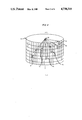
- FIG. 4 is a pictorial representation illustrating the scanning spot beam concept utilized by base station 10 of FIG. 1;
- FIG. 5 is a representation of an illustrative frequency reuse arrangement for the spot beam footprints of FIG. 3;
- FIG. 6 is a block schematic diagram of the circuit architecture within base station 10 of FIG. 1;
- FIG. 7 is an illustrative reduction of a 4 ⁇ 4 traffic matrix comprising 39 units of traffic for 3 transmitters and 3 receivers each of a capacity of 13, in accordance with the present invention.
- FIG. 8 is a TDMA frame assignment sequence for the exemplary reduction of FIG. 7.
- FIG. 1 shows a terrestrial communications system 100 in accordance with the present invention.
- the system includes a base station 10 which provides communications services among the customers 11 within a system service region 12.
- Region 12 is divided into sectors 13 where each sector may include one or more customers 11. While the representation of FIG. 1 is two dimensional, it should be understood that sectors 13 can be stacked one over the other so as to provide service region discrimination in a third dimension.
- Communication services between any customer in system 100 and any location not directly communicating with a base station 10 can also be advantageously provided through wire and radio communication links at the base station which interconnect with the public telecommunications network.
- FIG. 2 A panoramic view of the system service region as seen from base station 10 is shown in FIG. 2.
- the antenna 21 of each customer 11, represented by a +, is located at a particular azimuth and elevation.
- Communications services between customers 11 at any azimuth and elevation are routed through an antenna at base station 10 that provides a focussed M ⁇ N array of transmitting and a focussed M ⁇ N array of receiving radio spot beams.
- This use of focussed spot beams advantageously provides very high gain.
- communications services can be provided over a wide region with very low outage during rain attenuation even at the relatively uncongested higher frequency portions of the spectrum.
- spot beams provide the power required of high data rate operation, and the high signal isolation between spot beams permits frequency reuse, thereby accommodating large traffic demands within a relatively narrow spectral allocation.
- spot beams allows the use of inexpensive and small antennas which can be installed at a customer's rooftop or building window.
- Each customer location lies within one transmit and one receive spot beam and, hence, the array quantities M and N are determined by the number of customers and their locations.
- the base station also includes appropriate switching apparatus which interconnects spot beam receiving and transmitting antenna ports through a pool of radio transmitters and receivers typically far smaller than the number of transmitting or receiving spot beam ports. Accordingly, the number of receiving and transmitting ports interconnected at any time is equal to the number of available radio receivers and transmitters or the total traffic demand, whichever is less. With the pooling of equipment, the radio receivers and transmitters are effectively shared among a greater number of spot beams resulting in higher equipment utilization, lower system costs, and less interbeam interference.
- FIG. 3 shows an idealized representation of the M ⁇ N transmit or receive array of spot beams superimposed upon the panoramic view of FIG. 2.
- Each spot beam idealized as a square, is associated with a port on the base station antenna. These ports may take the form of discrete horns feeding a large main reflector or may be realized with a phased array.
- Activation of a particular transmitting or receiving port at the base station is made by means of Time-Division-Multiple-Access (TDMA) wherein time is divided into a sequence of repetitive frames, with each frame divided into some number C of time slots. Assignment of one or more time slots to a particular transmit/receive pair of base station spot beams is made in response to customer requests and varies dynamically with the traffic demand for each customer.
- TDMA Time-Division-Multiple-Access
- This selective activation of the transmit and receiver base station spot beams in accordance with a TDMA time slot effectively provides a "scanning" spot beam, i.e., the spot beam of energy into or out of the base station appears to be moving when, in reality, each feed or phased array element is fixed.
- base station 10 can be equipped with multiple pairs of transmitting and receiving equipment to permit traffic assignment into a plurality of parallel TDMA sequences. As a result, a plurality of transmit and receive beams can be activated, if traffic demand dictates, at the same time.
- Service region 12 blanketed by M ⁇ N arrays of transmitting and receiving base station spot beams, is represented by a solid cylinder.
- Each spot beam is represented by a pyramidal volume which extends from the base station 10, represented by point 40 on longitudinal axis 4--4, to the circumferential surface of the cylinder.
- base station 10 is simultaneously receiving three information channels from different customers 11 via focussed spot beams and/or from the public telecommunications network. This information is transmitted to the desired customers 11 via spot beams 41, 42 and 43.
- the scanning beam concept can be advantageously combined with frequency reuse to further reduce beam-to-beam interference and permit more system customers within a limited frequency spectrum.
- FIG. 5 which shows the frequency reuse concept applied to a portion of either the transmit or receive M ⁇ N array of spot beams.
- Each spot beam is a circle which is superimposed upon a portion of the M ⁇ N grid of FIG. 3.
- the designations f1 and f2 refer to two distinct radio frequencies.
- the subscripts H and V refer to two orthogonal polarizations which, for illustrative purposes, are respectively designated as the horizontal and vertical.
- spot beam 500 is a vertically polarized beam at frequency f1. None of the eight surrounding beams, designated as 501 through 508, have this polarization and frequency.
- each receiving port 510 and the M ⁇ N transmitting ports 520 are each assigned a frequency and polarization to blanket the service region, as illustrated in FIG. 5.
- Each receiving port including either a feedhorn or a particular phase setting of a plurality of phased array elements 511 serially connected to a radio frequency (RF) receiver 512, receives a radio spot beam having a preselected frequency and polarization.
- RF radio frequency
- each transmitting port 520 transmits a radio spot beam having a preselected frequency and polarization and includes an RF transmitter 522 which is serially connected to either a feedhorn or a particular phase setting of a plurality of phased array elements 521.
- the receiving ports and transmitting ports are respectively partitioned into groups 513-1 through 513-N and 514-1 through 514-N. Rather than tailor the number of receiving ports in each of the groups 513-1 through 513-N and the number of transmitting ports in each of the groups 514-1 through 514-N so that each group of transmitting or receiving ports handles substantially the same volume of traffic, the receiving ports and transmitting ports are arbitrarily partitioned into groups each having a plurality of Q receiving ports or Q transmitting ports. Traffic balancing is then achieved by respectively assigning to a group of receiving or transmitting ports a number of intermediate frequency (IF) receivers and IF transmitters proportional to the traffic intensity handled by that group.
- IF intermediate frequency
- Interconnection between the IF receivers and the receiving ports and between the IF transmitters and the transmitting ports is then provided via Q ⁇ J matrix switches, where J is ⁇ Q.
- J is ⁇ Q.
- the number of IF receivers associated with each receiving port group and the number of IF transmitters associated with each transmitting port group are, therefore, each limited to J.
- some of the J matrix switch ports are simply unused.
- values for Q are 32 or 64 and for J, are 8.
- each group of Q receiving ports 513-1 through 513-N is connected to a different one of the Q ⁇ J receive port matrix switches 515-1 through 515-N, with each receiving port in a group being connected to a different one of the Q switch terminals.
- These N groups of IF receivers are designated as 516-1 through 516-N.
- Each of the j IF receivers in any group is connected to a different one of the J switch matrix terminals with the J-j excess switch terminals, if any, being unused.
- each group of Q transmitting ports 514-1 through 514-N is connected to a different one of the Q ⁇ J transmit port matrix switches 517-1 through 517-N with each transmitting port in a group being connected to a different one of the Q switch terminals.
- the switch terminals of each transmit port matrix switch are connected to a different one of the j IF transmitters, where j is 1, 2 . . . J, associated with each transmitting port group and the J-j excess terminals, if any, are unused.
- These N groups of IF transmitters are designated as 518-1 through 518-N.
- the main switch 519 receives each of the IF receivers in groups 516-1 through 516-N on a different switch input terminal and each of the IF transmitters in groups 518-1 through 518-N on a different switch output terminal.
- TDMA frame assignments are formed by TDMA sequencer 553 in response to signalling information from each customer 11. This signalling information, requesting interconnection from any given customer to any other during one or more TDMA time slots, is inserted through the receive port matrix switches, the main switch 519 and thence to sequencer 553 via lead 565 in dedicated TDMA time slots. Each customer has a different, preselected time slot after a preselected number of TDMA frames to transmit this signalling information to sequencer 553.
- TDMA time slots associated with each customer 11 for transmitting signalling information from sequencer 553 to all the customers 11.
- This signalling information from sequencer 553 informs each customer of its assigned TDMA time slots and is routed from lead 566 through main switch 519 and transmit port matrix switches 517-1 through 517-N.
- This use of dedicated TDMA time slots for the transmission of signalling information is well-known and is described fully in U.S. Pat. No. 4,252,999 to Acampora et al., issued Feb. 24, 1981.
- the TDMA frame sequences formed by sequencer 553 are transmitted to digital interface unit 551 where they are stored in an internal memory.
- Unit 551 then executes the stored TDMA time slot assignments by transmitting the appropriate control signals to main switch 519 and the receive port and transmit port matrix switches 516-1 through 516-N and 517-1 through 517-N via buses 562 and 561, respectively.
- Master clock generator 552 establishes a master clock signal which establishes the TDMA frame and time slot timing for sequencer 553 and digital interface unit 551. Additionally, as the signalling information from sequencer 553 to all the customers is synchronized with the master clock, the customers can synchronize their local checks from this signalling information and thereby provide a fully synchronized communications system.
- the present communications system can be adapted to provide communications services between customers who communicate with the base station via radio spot beams as described hereinabove and customers who communicate with the base slots on public telecommunications links.
- one or more receive ports and one or more transmit ports on main switch 519 can be connected to wire or radio public communications facilities. These facilities can then be treated as any other system customer and assigned TDMA time slots in accordance with interconnection requests received by TDMA sequencer 553.
- Equation (2) is a statement of the fact that the total traffic arising in any footprint cannot exceed the number of time slots in a frame (or else two or more base station receivers would need to be connected to the same footprint to accept this traffic, causing interference).
- equation (3) is a statement of the fact that the total traffic destined for any footprint cannot exceed the number of time slots in the frame.
- equation (4) is a statement of the fact that the total offered traffic cannot exceed the total number of time slots in all P frames.
- a new matrix T exists with the properties that (1) no row sum exceeds C-1, (2) no column sum exceeds C-1, and (3) the total traffic is less than P(C-1).
- a second diagonal can be found covering all rows and columns (if any) of T summing to (C-1); one unit of traffic from each element may be assigned to the second time slots of the frames. Proceeding in this manner, all traffic from T may be assigned without conflict.
- the assignments are not unique and it may be possible to extract more than one unit of traffic per diagonal element at a time. This is desirable from a practical point of view as it minimizes the number of times the matrix switches and main switch have to be reconfigured during one TDMA frame period. To achieve this, it seems desirable to choose the diagonal elements from large elements in the rows and columns with the largest sums, if possible.
- FIG. 7 shows the generation of three TDMA parallel frame sequences from a traffic matrix T.
- the diagonal elements chosen from matrix T are circled and the rows and columns which sum to the reduced value of C, if any, are marked with an asterisk.
- six units of traffic are available from the diagonals chosen in matrix (a) but only five units are selected therefrom since, as was stated hereinabove, the maximum traffic extractable is the smaller of either t 1 , the smallest element on the diagonal, which equals six or C-t 2 , the largest capacity of the row or column of the rows or columns not covered by the diagonal elements chosen, which equals 13-8 or 5 and is here determinative.
- the corresponding traffic assignments to each of the three TDMA frames is also shown in FIG. 8.
- the TDMA sequences must compare the assignments against the equipment pool of available IF receivers and IF transmitters which must be interconnected to fulfill these assignments. For example, referring to FIG. 6, the diagonal selected must cover the beams corresponding to the ports 513-1 a number of times equal to the number of IF receivers 516-1 connected to the ports via switch 515-1. The same must be true for all other receive ports 513-2 through 513-N and for all transmit ports 514-1 through 514-N. If the assignments made exceed the available equipment pool, the assignments made are disregarded and different diagonals are selected. It is typically easy to find the required diagonals. TDMA sequencer 553 can also advantageously store a list of undesirable traffic assignments for simultaneous time slots in the parallel TDMA frames.
- undesirable traffic assignments would be based on apriori knowledge of the radio signal interference generated by the simultaneous transmission from certain selected customers. As with the available equipment pool, a comparison of the TDMA assignments and the undesirable traffic assignments would be made. If any of these undesirable traffic assignments appear in the TDMA frames, a different set of diagonals would be selected, corresponding to permissible time slot assignments. The different set of diagonals would include at least one diagonal not in the prior diagonal set. This selection of a different set of diagonals would continue until assignments result which do not exceed the available equipment and do not include undesirable traffic assignments.
- the disclosed embodiment is merely illustrative and that alternate arrangements may be envisioned by those skilled in the art without departing from the spirit and scope of the present invention.
- the present invention is not restricted in principle to such signals.
- the present invention can provide optical communications, e.g., infra-red signal transmission and reception, by merely changing the rf receivers and transmitters to receivers and transmitters which operate in this frequency band. Accordingly, the term "radio" and "rf" will be deemed to refer to electromagnetic radiation lying outside of the classical frequency range of such signals.
Landscapes
- Engineering & Computer Science (AREA)
- Computer Networks & Wireless Communication (AREA)
- Signal Processing (AREA)
- Mobile Radio Communication Systems (AREA)
- Time-Division Multiplex Systems (AREA)
- Use Of Switch Circuits For Exchanges And Methods Of Control Of Multiplex Exchanges (AREA)
Priority Applications (1)
| Application Number | Priority Date | Filing Date | Title |
|---|---|---|---|
| US06/843,842 US4730310A (en) | 1985-05-03 | 1986-03-26 | Terrestrial communications system |
Applications Claiming Priority (2)
| Application Number | Priority Date | Filing Date | Title |
|---|---|---|---|
| US72991585A | 1985-05-03 | 1985-05-03 | |
| US06/843,842 US4730310A (en) | 1985-05-03 | 1986-03-26 | Terrestrial communications system |
Related Parent Applications (1)
| Application Number | Title | Priority Date | Filing Date |
|---|---|---|---|
| US72991585A Continuation-In-Part | 1985-05-03 | 1985-05-03 |
Publications (1)
| Publication Number | Publication Date |
|---|---|
| US4730310A true US4730310A (en) | 1988-03-08 |
Family
ID=24933125
Family Applications (1)
| Application Number | Title | Priority Date | Filing Date |
|---|---|---|---|
| US06/843,842 Expired - Lifetime US4730310A (en) | 1985-05-03 | 1986-03-26 | Terrestrial communications system |
Country Status (6)
| Country | Link |
|---|---|
| US (1) | US4730310A (de) |
| EP (1) | EP0201254B1 (de) |
| JP (2) | JPS6210997A (de) |
| AU (1) | AU564221B2 (de) |
| CA (1) | CA1250647A (de) |
| DE (1) | DE3686506T2 (de) |
Cited By (24)
| Publication number | Priority date | Publication date | Assignee | Title |
|---|---|---|---|---|
| US4775998A (en) * | 1987-07-20 | 1988-10-04 | Motorola, Inc. | Cellular radiotelephone system having colocated base sites |
| US4799253A (en) * | 1987-07-20 | 1989-01-17 | Motorola, Inc. | Colocated cellular radiotelephone systems |
| US4858229A (en) * | 1986-08-14 | 1989-08-15 | Hughes Aircraft Company | Filter interconnection matrix |
| US4879711A (en) * | 1986-08-14 | 1989-11-07 | Hughes Aircraft Company | Satellite communications system employing frequency reuse |
| EP0483546A1 (de) | 1990-10-29 | 1992-05-06 | International Business Machines Corporation | Verfahren zum Abfragen von mobielen Benutzern in einem vielzelligen drahtlosen Netzwerk |
| US5212806A (en) * | 1990-10-29 | 1993-05-18 | International Business Machines Corporation | Distributed control methods for management of migrating data stations in a wireless communications network |
| US5230082A (en) * | 1990-08-16 | 1993-07-20 | Telefonaktiebolaget L M Ericsson | Method and apparatus for enhancing signalling reliability in a cellular mobile radio telephone system |
| US5239673A (en) * | 1990-10-29 | 1993-08-24 | International Business Machines Corporation | Scheduling methods for efficient frequency reuse in a multi-cell wireless network served by a wired local area network |
| US5274841A (en) * | 1990-10-29 | 1993-12-28 | International Business Machines Corporation | Methods for polling mobile users in a multiple cell wireless network |
| US5479478A (en) * | 1993-01-29 | 1995-12-26 | Boeing Information Services, Inc. | Method and system for pull communication |
| US5719868A (en) * | 1995-10-05 | 1998-02-17 | Rockwell International | Dynamic distributed, multi-channel time division multiple access slot assignment method for a network of nodes |
| US5898382A (en) * | 1997-02-12 | 1999-04-27 | Treatch; James E. | Shared channel communication system |
| EP0777400A3 (de) * | 1995-11-29 | 1999-05-12 | Trw Inc. | Zellulares Kommunikationssystem mit teilnehmergerichtetem Strahl |
| US5933787A (en) * | 1995-03-13 | 1999-08-03 | Qualcomm Incorporated | Method and apparatus for performing handoff between sectors of a common base station |
| US5949760A (en) * | 1997-03-21 | 1999-09-07 | Rockwell International Corporation | Simultaneous channel access transmission method for a multi-hop communications radio network |
| US6046701A (en) * | 1997-11-03 | 2000-04-04 | Spike Technologies, Inc. | Apparatus for high-performance sectored antenna system |
| US6125109A (en) * | 1998-02-24 | 2000-09-26 | Repeater Technologies | Delay combiner system for CDMA repeaters and low noise amplifiers |
| US6169525B1 (en) | 1998-09-10 | 2001-01-02 | Spike Technologies, Inc. | High-performance sectored antenna system using low profile broadband feed devices |
| US6323980B1 (en) * | 1998-03-05 | 2001-11-27 | Air Fiber, Inc. | Hybrid picocell communication system |
| US6418327B1 (en) | 1999-04-06 | 2002-07-09 | Spike Broadband Systems, Inc. | Methods and determining an optimum sector distribution within a coverage area of a wireless communication system |
| USRE37820E1 (en) | 1994-06-28 | 2002-08-13 | Littlefeet, Inc. | Arrangements of base transceiver stations of an area-covering network |
| US6975600B1 (en) * | 2000-09-18 | 2005-12-13 | The Directv Group, Inc. | Multimode transmission system using TDMA |
| US20110250883A1 (en) * | 2010-04-08 | 2011-10-13 | Itt Manufacturing Enterprises, Inc. | Monitoring of Network Call Activity in a Satellite-Based Communication System |
| EP2709396A1 (de) * | 2012-09-13 | 2014-03-19 | Alcatel-Lucent | Mehrstrahl-Funkbasisstation |
Families Citing this family (26)
| Publication number | Priority date | Publication date | Assignee | Title |
|---|---|---|---|---|
| US4825448A (en) * | 1986-08-07 | 1989-04-25 | International Mobile Machines Corporation | Subscriber unit for wireless digital telephone system |
| SE8803094D0 (sv) * | 1988-09-05 | 1988-09-05 | Joakim Nelson | Ytteckande tradlosa telekommunikationssystem med tids, frekvens och rymdstyrning |
| US5448753A (en) * | 1988-09-05 | 1995-09-05 | Ahl; Karl-Axel | Wide area radio communication network system and method |
| US5048116A (en) * | 1989-05-24 | 1991-09-10 | Motorola, Inc. | Signal routing system |
| SE8903455D0 (sv) * | 1989-10-19 | 1989-10-19 | Joakim Nelson | Dynamiska digitala foerbindelsenaet (dfn) |
| SE9200283D0 (sv) * | 1992-02-03 | 1992-02-03 | Peter Aahl | Dynamisk varierbar radiostation-dvr |
| ATE192276T1 (de) * | 1994-03-17 | 2000-05-15 | Endlink Inc | Sektorisiertes mehrzweck cellulares funkubertragungssystem |
| US5771449A (en) * | 1994-03-17 | 1998-06-23 | Endlink, Inc. | Sectorized multi-function communication system |
| US5548813A (en) * | 1994-03-24 | 1996-08-20 | Ericsson Inc. | Phased array cellular base station and associated methods for enhanced power efficiency |
| US6201801B1 (en) | 1994-03-24 | 2001-03-13 | Ericsson Inc. | Polarization diversity phased array cellular base station and associated methods |
| US6151310A (en) * | 1994-03-24 | 2000-11-21 | Ericsson Inc. | Dividable transmit antenna array for a cellular base station and associated method |
| GB9417128D0 (en) * | 1994-08-24 | 1994-10-12 | Plessey Semiconductors Ltd | Wirreless local area network system |
| GB9417318D0 (en) * | 1994-08-27 | 1994-10-19 | Philips Electronics Uk Ltd | Microwave cellular communications system and adaptable microwave transmitter |
| US6006069A (en) * | 1994-11-28 | 1999-12-21 | Bosch Telecom Gmbh | Point-to-multipoint communications system |
| US6112056A (en) | 1995-06-07 | 2000-08-29 | Cisco Systems, Inc. | Low power, short range point-to-multipoint communications system |
| GB9519116D0 (en) * | 1995-09-19 | 1995-11-22 | Northern Telecom Ltd | Cellular communications system |
| US5781864A (en) * | 1996-05-20 | 1998-07-14 | Metawave Communications Corporation | Cellular system conditioner which overrides a disconnect for active radios wirelessly communicating with mobiles located in pre-identified territorial positions |
| US6141557A (en) * | 1996-05-31 | 2000-10-31 | The Whitaker Corporation | LMDS system having cell-site diversity and adaptability |
| EP0903048B1 (de) * | 1996-05-31 | 2008-04-16 | The Whitaker Corporation | Lmds-system mit feststation-diversity und anpassungsfähigkeit |
| US5838670A (en) * | 1997-01-29 | 1998-11-17 | Telefonaktiebolaget L M Ericsson | Point to multipoint radio access system |
| US6104930A (en) * | 1997-05-02 | 2000-08-15 | Nortel Networks Corporation | Floating transceiver assignment for cellular radio |
| US6665296B1 (en) | 1999-12-09 | 2003-12-16 | Social Fabric Corporation | Network access communication system |
| US7231214B2 (en) | 2000-12-08 | 2007-06-12 | Harris Corporation | System and method for frequency re-use in a sectorized cell pattern in a wireless communication system |
| AU2002220251A1 (en) * | 2000-12-08 | 2002-06-18 | Harris Broadband Wireless Access, Inc. | System and method for inband signaling for sector synchronization in a wireless communication system |
| FR2820257B1 (fr) * | 2001-01-26 | 2004-05-28 | Thomson Csf | Systeme radio haute capacite |
| US9681455B2 (en) * | 2010-01-28 | 2017-06-13 | Alcatel Lucent | Methods for reducing interference in a communication system |
Citations (7)
| Publication number | Priority date | Publication date | Assignee | Title |
|---|---|---|---|---|
| US4092600A (en) * | 1975-08-27 | 1978-05-30 | Autophon Aktiengesellschaft | Installation for two-way radio communication |
| US4232266A (en) * | 1978-09-05 | 1980-11-04 | Bell Telephone Laboratories, Incorporated | Technique for sharing a plurality of transponders among a same or larger number of channels |
| US4252999A (en) * | 1978-10-04 | 1981-02-24 | Bell Telephone Laboratories, Incorporated | Signaling and ranging technique for a TDMA satellite communication system |
| US4315262A (en) * | 1979-04-26 | 1982-02-09 | Bell Telephone Laboratories, Incorporated | Satellite communication system with a plurality of limited scan spot beams |
| US4513412A (en) * | 1983-04-25 | 1985-04-23 | At&T Bell Laboratories | Time division adaptive retransmission technique for portable radio telephones |
| US4578815A (en) * | 1983-12-07 | 1986-03-25 | Motorola, Inc. | Wide area coverage radio communication system and method |
| US4633463A (en) * | 1984-03-28 | 1986-12-30 | Canadian Marconi Corporation | Radio communication system |
Family Cites Families (5)
| Publication number | Priority date | Publication date | Assignee | Title |
|---|---|---|---|---|
| DE2659638B1 (de) * | 1976-12-30 | 1978-05-11 | Siemens Ag | Funksystem zum Anschluss ortsfester Teilnehmerstationen an ein Nachrichtennetz |
| JPS5656089A (en) * | 1979-10-12 | 1981-05-16 | Nec Corp | Remote control time-division exchange system |
| JPS596535B2 (ja) * | 1980-01-09 | 1984-02-13 | 日本電信電話株式会社 | 衛星通信方式 |
| JPS56109050A (en) * | 1980-02-01 | 1981-08-29 | Nippon Telegr & Teleph Corp <Ntt> | Radio communication system for scanning beam |
| JPS59224936A (ja) * | 1983-06-04 | 1984-12-17 | Nec Corp | 時分割多方向多重通信装置 |
-
1986
- 1986-03-26 US US06/843,842 patent/US4730310A/en not_active Expired - Lifetime
- 1986-04-28 DE DE8686303185T patent/DE3686506T2/de not_active Expired - Fee Related
- 1986-04-28 EP EP86303185A patent/EP0201254B1/de not_active Expired
- 1986-05-01 CA CA000508136A patent/CA1250647A/en not_active Expired
- 1986-05-01 AU AU57084/86A patent/AU564221B2/en not_active Ceased
- 1986-05-02 JP JP61101229A patent/JPS6210997A/ja active Pending
-
1995
- 1995-09-18 JP JP009788U patent/JPH081390U/ja active Pending
Patent Citations (7)
| Publication number | Priority date | Publication date | Assignee | Title |
|---|---|---|---|---|
| US4092600A (en) * | 1975-08-27 | 1978-05-30 | Autophon Aktiengesellschaft | Installation for two-way radio communication |
| US4232266A (en) * | 1978-09-05 | 1980-11-04 | Bell Telephone Laboratories, Incorporated | Technique for sharing a plurality of transponders among a same or larger number of channels |
| US4252999A (en) * | 1978-10-04 | 1981-02-24 | Bell Telephone Laboratories, Incorporated | Signaling and ranging technique for a TDMA satellite communication system |
| US4315262A (en) * | 1979-04-26 | 1982-02-09 | Bell Telephone Laboratories, Incorporated | Satellite communication system with a plurality of limited scan spot beams |
| US4513412A (en) * | 1983-04-25 | 1985-04-23 | At&T Bell Laboratories | Time division adaptive retransmission technique for portable radio telephones |
| US4578815A (en) * | 1983-12-07 | 1986-03-25 | Motorola, Inc. | Wide area coverage radio communication system and method |
| US4633463A (en) * | 1984-03-28 | 1986-12-30 | Canadian Marconi Corporation | Radio communication system |
Non-Patent Citations (6)
| Title |
|---|
| J. W. Ballance, "A Low-Cost TDM/TDMA Subsystem for Point-to-Multipoint Local Distribution", Br Telecom Technol J, vol. 2, No. 2, Apr. 1984. |
| J. W. Ballance, A Low Cost TDM/TDMA Subsystem for Point to Multipoint Local Distribution , Br Telecom Technol J, vol. 2, No. 2, Apr. 1984. * |
| R. P. Scott, "A Low Cost 19 GHz Radio Sub-System for Point-to-Multipoint Radio Applications", Br Telecom Technol J, vol. 2, No. 3, Jul. 1984, pp. 50-57. |
| R. P. Scott, A Low Cost 19 GHz Radio Sub System for Point to Multipoint Radio Applications , Br Telecom Technol J, vol. 2, No. 3, Jul. 1984, pp. 50 57. * |
| S. A. Mohamed et al, "29 GHz point-to-point radio systems for local distribution", Br Telecom Technol J, vol. 2, No. 1, Jan. 1984, pp. 29-40. |
| S. A. Mohamed et al, 29 GHz point to point radio systems for local distribution , Br Telecom Technol J, vol. 2, No. 1, Jan. 1984, pp. 29 40. * |
Cited By (29)
| Publication number | Priority date | Publication date | Assignee | Title |
|---|---|---|---|---|
| US4858229A (en) * | 1986-08-14 | 1989-08-15 | Hughes Aircraft Company | Filter interconnection matrix |
| US4879711A (en) * | 1986-08-14 | 1989-11-07 | Hughes Aircraft Company | Satellite communications system employing frequency reuse |
| US4775998A (en) * | 1987-07-20 | 1988-10-04 | Motorola, Inc. | Cellular radiotelephone system having colocated base sites |
| US4799253A (en) * | 1987-07-20 | 1989-01-17 | Motorola, Inc. | Colocated cellular radiotelephone systems |
| US4893327A (en) * | 1987-07-20 | 1990-01-09 | Motorola, Inc. | Colocated cellular radiotelephone systems |
| US5230082A (en) * | 1990-08-16 | 1993-07-20 | Telefonaktiebolaget L M Ericsson | Method and apparatus for enhancing signalling reliability in a cellular mobile radio telephone system |
| EP0483546A1 (de) | 1990-10-29 | 1992-05-06 | International Business Machines Corporation | Verfahren zum Abfragen von mobielen Benutzern in einem vielzelligen drahtlosen Netzwerk |
| US5212806A (en) * | 1990-10-29 | 1993-05-18 | International Business Machines Corporation | Distributed control methods for management of migrating data stations in a wireless communications network |
| US5239673A (en) * | 1990-10-29 | 1993-08-24 | International Business Machines Corporation | Scheduling methods for efficient frequency reuse in a multi-cell wireless network served by a wired local area network |
| US5274841A (en) * | 1990-10-29 | 1993-12-28 | International Business Machines Corporation | Methods for polling mobile users in a multiple cell wireless network |
| US5479478A (en) * | 1993-01-29 | 1995-12-26 | Boeing Information Services, Inc. | Method and system for pull communication |
| USRE37820E1 (en) | 1994-06-28 | 2002-08-13 | Littlefeet, Inc. | Arrangements of base transceiver stations of an area-covering network |
| US6459900B1 (en) | 1994-06-28 | 2002-10-01 | Littlefeet, Inc. | Methods of operating arrangements of base transceiver stations in an area-covering network |
| US5933787A (en) * | 1995-03-13 | 1999-08-03 | Qualcomm Incorporated | Method and apparatus for performing handoff between sectors of a common base station |
| US5719868A (en) * | 1995-10-05 | 1998-02-17 | Rockwell International | Dynamic distributed, multi-channel time division multiple access slot assignment method for a network of nodes |
| EP0777400A3 (de) * | 1995-11-29 | 1999-05-12 | Trw Inc. | Zellulares Kommunikationssystem mit teilnehmergerichtetem Strahl |
| US5898382A (en) * | 1997-02-12 | 1999-04-27 | Treatch; James E. | Shared channel communication system |
| US5949760A (en) * | 1997-03-21 | 1999-09-07 | Rockwell International Corporation | Simultaneous channel access transmission method for a multi-hop communications radio network |
| US6046701A (en) * | 1997-11-03 | 2000-04-04 | Spike Technologies, Inc. | Apparatus for high-performance sectored antenna system |
| US6125109A (en) * | 1998-02-24 | 2000-09-26 | Repeater Technologies | Delay combiner system for CDMA repeaters and low noise amplifiers |
| US6323980B1 (en) * | 1998-03-05 | 2001-11-27 | Air Fiber, Inc. | Hybrid picocell communication system |
| US6169525B1 (en) | 1998-09-10 | 2001-01-02 | Spike Technologies, Inc. | High-performance sectored antenna system using low profile broadband feed devices |
| US6418327B1 (en) | 1999-04-06 | 2002-07-09 | Spike Broadband Systems, Inc. | Methods and determining an optimum sector distribution within a coverage area of a wireless communication system |
| US6975600B1 (en) * | 2000-09-18 | 2005-12-13 | The Directv Group, Inc. | Multimode transmission system using TDMA |
| US20110250883A1 (en) * | 2010-04-08 | 2011-10-13 | Itt Manufacturing Enterprises, Inc. | Monitoring of Network Call Activity in a Satellite-Based Communication System |
| US8483608B2 (en) * | 2010-04-08 | 2013-07-09 | Exelis Inc. | Monitoring of network call activity in a satellite-based communication system |
| EP2709396A1 (de) * | 2012-09-13 | 2014-03-19 | Alcatel-Lucent | Mehrstrahl-Funkbasisstation |
| WO2014040712A1 (en) * | 2012-09-13 | 2014-03-20 | Alcatel Lucent | Radio cells |
| US10057778B2 (en) | 2012-09-13 | 2018-08-21 | Wsou Investments, Llc | Radio cells |
Also Published As
| Publication number | Publication date |
|---|---|
| JPS6210997A (ja) | 1987-01-19 |
| DE3686506D1 (de) | 1992-10-01 |
| EP0201254A3 (en) | 1988-07-06 |
| JPH081390U (ja) | 1996-09-13 |
| EP0201254A2 (de) | 1986-11-12 |
| DE3686506T2 (de) | 1993-02-11 |
| AU564221B2 (en) | 1987-08-06 |
| CA1250647A (en) | 1989-02-28 |
| AU5708486A (en) | 1986-11-06 |
| EP0201254B1 (de) | 1992-08-26 |
Similar Documents
| Publication | Publication Date | Title |
|---|---|---|
| US4730310A (en) | Terrestrial communications system | |
| CA1288480C (en) | Satellite communications system employing frequency reuse | |
| US4315262A (en) | Satellite communication system with a plurality of limited scan spot beams | |
| US4813036A (en) | Fully interconnected spot beam satellite communication system | |
| US4232266A (en) | Technique for sharing a plurality of transponders among a same or larger number of channels | |
| US5603089A (en) | Base station antenna arrangement | |
| US4381562A (en) | Broadcast type satellite communication systems | |
| EP1410657B1 (de) | Frequenzwiederbenutzung für punkt-zu-mehrpunkt-anwendungen | |
| CA2433391C (en) | Communication system for mobile users using adaptive antenna | |
| US5771017A (en) | Base station antenna arrangement | |
| US6088341A (en) | Method for reducing co-channel of cross-polarization interference in a satellite data communication system by offsetting channel frequencies | |
| US5576717A (en) | Base station antenna arrangement | |
| US6006113A (en) | Radio signal scanning and targeting system for use in land mobile radio base sites | |
| EP0647980A2 (de) | Antenneneinrichtung für Basisstation | |
| GB2281175A (en) | Base station antenna arrangement | |
| GB2281012A (en) | Angle diversity for multiple beam antenna | |
| JPH04233804A (ja) | 多重、周波数アドレス可能な走査ビームを生成する方法および装置 | |
| Acampora et al. | Efficient Utilization of Satellite Transponders via Time‐Division Multibeam Scanning | |
| US6577869B1 (en) | Frequency re-use for TDD applications | |
| CA2276253C (en) | Frequency assigning method for an eight cell frequency re-use plan | |
| GB2281009A (en) | Base station antenna arrangement | |
| ES2910940T3 (es) | Arquitectura de carga útil flexible para aplicaciones VHTS y HTS | |
| Acampora et al. | A satellite system with limited-scan spot beams | |
| US7835733B1 (en) | Satellite telecommunication system | |
| GB2281008A (en) | Base station antenna arrangement |
Legal Events
| Date | Code | Title | Description |
|---|---|---|---|
| AS | Assignment |
Owner name: BELL TELELPHONE LABORATORIES, INCORPORATED, 600 MO Free format text: ASSIGNMENT OF ASSIGNORS INTEREST.;ASSIGNORS:ACAMPORA, ANTHONY;CHU, TA-SHING;DRAGONE, CORRADO;AND OTHERS;REEL/FRAME:004571/0942 Effective date: 19860321 |
|
| STCF | Information on status: patent grant |
Free format text: PATENTED CASE |
|
| FEPP | Fee payment procedure |
Free format text: PAYOR NUMBER ASSIGNED (ORIGINAL EVENT CODE: ASPN); ENTITY STATUS OF PATENT OWNER: LARGE ENTITY |
|
| FPAY | Fee payment |
Year of fee payment: 4 |
|
| FPAY | Fee payment |
Year of fee payment: 8 |
|
| FEPP | Fee payment procedure |
Free format text: PAYER NUMBER DE-ASSIGNED (ORIGINAL EVENT CODE: RMPN); ENTITY STATUS OF PATENT OWNER: LARGE ENTITY Free format text: PAYOR NUMBER ASSIGNED (ORIGINAL EVENT CODE: ASPN); ENTITY STATUS OF PATENT OWNER: LARGE ENTITY |
|
| FPAY | Fee payment |
Year of fee payment: 12 |