US4732202A - Vertical louvre blind traveller - Google Patents
Vertical louvre blind traveller Download PDFInfo
- Publication number
- US4732202A US4732202A US06/853,818 US85381886A US4732202A US 4732202 A US4732202 A US 4732202A US 85381886 A US85381886 A US 85381886A US 4732202 A US4732202 A US 4732202A
- Authority
- US
- United States
- Prior art keywords
- traveller
- strip
- spacer
- headrail
- housing
- Prior art date
- Legal status (The legal status is an assumption and is not a legal conclusion. Google has not performed a legal analysis and makes no representation as to the accuracy of the status listed.)
- Expired - Fee Related
Links
- 125000006850 spacer group Chemical group 0.000 claims abstract description 81
- 238000000926 separation method Methods 0.000 claims description 10
- 230000004323 axial length Effects 0.000 claims 2
- 230000000717 retained effect Effects 0.000 claims 1
- 229910001220 stainless steel Inorganic materials 0.000 abstract description 4
- 239000010935 stainless steel Substances 0.000 abstract description 4
- 239000011324 bead Substances 0.000 description 5
- 238000003780 insertion Methods 0.000 description 2
- 230000037431 insertion Effects 0.000 description 2
- 238000005452 bending Methods 0.000 description 1
- 239000000969 carrier Substances 0.000 description 1
- 230000013011 mating Effects 0.000 description 1
- 238000000034 method Methods 0.000 description 1
- 230000000284 resting effect Effects 0.000 description 1
- 238000011282 treatment Methods 0.000 description 1
- 230000007306 turnover Effects 0.000 description 1
Images



Classifications
-
- E—FIXED CONSTRUCTIONS
- E06—DOORS, WINDOWS, SHUTTERS, OR ROLLER BLINDS IN GENERAL; LADDERS
- E06B—FIXED OR MOVABLE CLOSURES FOR OPENINGS IN BUILDINGS, VEHICLES, FENCES OR LIKE ENCLOSURES IN GENERAL, e.g. DOORS, WINDOWS, BLINDS, GATES
- E06B9/00—Screening or protective devices for wall or similar openings, with or without operating or securing mechanisms; Closures of similar construction
- E06B9/24—Screens or other constructions affording protection against light, especially against sunshine; Similar screens for privacy or appearance; Slat blinds
- E06B9/26—Lamellar or like blinds, e.g. venetian blinds
- E06B9/36—Lamellar or like blinds, e.g. venetian blinds with vertical lamellae ; Supporting rails therefor
- E06B9/362—Travellers; Lamellae suspension stems
-
- E—FIXED CONSTRUCTIONS
- E06—DOORS, WINDOWS, SHUTTERS, OR ROLLER BLINDS IN GENERAL; LADDERS
- E06B—FIXED OR MOVABLE CLOSURES FOR OPENINGS IN BUILDINGS, VEHICLES, FENCES OR LIKE ENCLOSURES IN GENERAL, e.g. DOORS, WINDOWS, BLINDS, GATES
- E06B9/00—Screening or protective devices for wall or similar openings, with or without operating or securing mechanisms; Closures of similar construction
- E06B9/24—Screens or other constructions affording protection against light, especially against sunshine; Similar screens for privacy or appearance; Slat blinds
- E06B9/26—Lamellar or like blinds, e.g. venetian blinds
- E06B9/36—Lamellar or like blinds, e.g. venetian blinds with vertical lamellae ; Supporting rails therefor
- E06B9/362—Travellers; Lamellae suspension stems
- E06B9/365—Distance pieces therefor
-
- Y—GENERAL TAGGING OF NEW TECHNOLOGICAL DEVELOPMENTS; GENERAL TAGGING OF CROSS-SECTIONAL TECHNOLOGIES SPANNING OVER SEVERAL SECTIONS OF THE IPC; TECHNICAL SUBJECTS COVERED BY FORMER USPC CROSS-REFERENCE ART COLLECTIONS [XRACs] AND DIGESTS
- Y10—TECHNICAL SUBJECTS COVERED BY FORMER USPC
- Y10S—TECHNICAL SUBJECTS COVERED BY FORMER USPC CROSS-REFERENCE ART COLLECTIONS [XRACs] AND DIGESTS
- Y10S160/00—Flexible or portable closure, partition, or panel
- Y10S160/90—Vertical type venetian blind
Definitions
- the invention relates to window treatments and in particular to vertical Louvre Blinds and travellers therefor.
- Vertical louvre blinds usually comprise a headrail with several travellers movable along the headrail by one means or another. Each of the travellers has a rotatable hook which holds a vane carrier. The vane carriers in turn hold the vanes or louvres of the blind.
- the travellers are capable of moving longitudinally along the headrail and imparting rotary movement to the hooks to rotate or tilt the louvres. The rotation is such that all of the louvres are operated simultaneously so that they always extend in planes substantially parallel to one another. Provision is often made to allow the blinds to move slightly if they are inadvertently hit.
- the travellers are pulled through the headrail by a cord attached to a lead traveller.
- a cord attached to a lead traveller.
- the spacer means pulls adjacent travellers along at predetermined separations. This provides even spacing between the travellers when extended.
- the lead traveller moves back towards its adjacent traveller providing slack in the separation means.
- the lead traveller collides with the second traveller and pushes it along. These travellers continue along to stack each adjacent traveller and pushing all the travellers back to the retracted position.
- the Present invention provides a more compact traveller than those previously known.
- the traveller allows closer stacking of the travellers in the retracted position and a smaller head rail. This provides less dead area which is covered by the louvres when they are fully retracted. Smaller travellers require that a greater number of spacers for the travellers will pass over each traveller in the retracted position. It is therefore an object of the present invention to provide a spacer which stacks in a compact manner thereby allowing the headrail dimensions to be reduced.
- the modified form of spacer used in the present invention permits a novel attachment technique.
- the spacer is made of a thin strip of stainless steel.
- the strip has a hook like portion which engages a slot in an adjacent spacer when the travellers are extended. On retraction, the hook disengages from the slot and slides on top of the adjacent spacer.
- the spacers are biased into engagement via a wire spring clip. As the travellers retracted the spacers stack closely one above the other.
- the travellers are provided with rollers which roll in a track in the headrail.
- rollers which roll in a track in the headrail.
- two cantilever wings extend forwardly from the traveller to maintain its orientation. The wings diverge slightly to receive the next housing between them in a nested fashion.
- the invention further includes a novel form of bridle which permits a headrail to be modified as a center draw headrail.
- a center draw headrail the travellers move from either side of the headrail to the center when they are extended.
- only one lead traveller can be tied to the ends of the closing cord, it is necessary to provide attachment for the bridle of the second lead traveller to an intermediate section of the cord.
- a bite or loop is formed in the closing cord. This loop is inserted through an opening in the bridle from above the bridle to below the bridle. The loop is then hooked over a post on the bottom of the bridle. Two sharp corners are provided on either side of the post such that tension on the cord in either direction engages the cord with one of the corners to prevent slipping.
- the invention also includes a novel retainer for use with the traveller.
- the retainer is a wire bent to form a bottom leg having two cantilevered end portions spaced from the bottom leg.
- the end portions are resilient.
- One end of the retainer is inserted into an opening which is smaller than the separation of the end portion and bottom leg. This biases the end portion toward the bottom leg so the end portion and bottom leg frictionally engage the opening to hold the retainer in place.
- the opposite end of the retainer extends over a worm wheel of the traveller and surrounds the spacer.
- the above described spacers are positioned between the bottom leg and end portions of the retainer. The resilient end portions thereby serve to bias the spacers of two adjacent travellers into face to face contact.
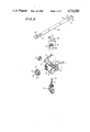
- FIG. 1 is a partially cutaway perspective view of the headrail of the invention showing a traveller of the invention
- FIG. 2 is an exploded view of the traveller of the invention
- FIG. 3 is a cross-sectional view of the traveller of the invention within a headrail
- FIG. 4 is an enlarged side view of the retainer clip of the invention.
- FIG. 5 is a top view of the spacer of the invention.
- FIG. 6 is a side view of the spacer of FIG. 5;
- FIG. 7 is a top perspective view of the bridle of the invention.
- FIG. 8 is a top view of the bridle of FIG. 7;
- FIG. 9 is an exploded view of a first end cap for the headrail, of the invention.
- FIG. 10 is a bottom perspective cutaway view of a headrail showing the bridle of FIG. 7;
- FIG. 11 is an exploded view of the second end cap of the invention showing the tilt rod rotating mechanism
- FIG. 12 is a cross-sectional view of a portion of a headrail the end cap of FIG. 9 and the end spacer of the invention.
- FIG. 13 is a cross-sectional view of a portion of a headrail, the end cap of FIG. 11 and an end spacer of the invention
- FIG. 14 is an exploded view of the pull cord weight of the invention.
- FIG. 15 is a view of the rotator cord tassel with stop
- FIG. 16 is an exploded view of the shaft, spring and mounting bracket for spring biasing the cord weight of FIG. 17;
- FIG. 17 is a cutaway view of the spring biased cord weight of the invention.
- FIG. 1 there is shown a headrail 1 having at least one traveller 2 disposed therein.
- the traveller 2 shown is an intermediate traveller.
- the lead traveller will be described below in connection with FIGS. 7 and 8.
- the traveller has a pair of wheels 3 which are mounted on shafts 4 on either side of the traveller housing 5.
- the wheels ride on ledges 6 formed within the headrail.
- the wheels 3 provide low friction movement of the traveller 2 within headrail 1.
- the traveller housing 5 is provided with a pair of cantilevered wings 7 which extend forwardly from the traveller 2, at a slightly diverging angle.
- the wings 7 engage the walls of the headrail to maintain the proper orientation of the traveller with the headrail so the traveller remains with wheel 3 resting on ledges 6 and therefor prevent cocking of the traveller relative the tilt rod which would increase the friction of motion.
- the tilting mechanism for the louvres (not shown) is contained within traveller housing 5 (FIG. 2).
- a worm wheel 8 is mounted in a known manner in a vertical cylindrical opening 9 in the traveller housing.
- the worm wheel 8 has an axial passage therethrough and a notch 10 in its side at one end.
- a slat hook 11 for holding a slat is provided with a shank 12 for insertion into the passageway, of the worm wheel 8.
- a barb 13 engages in the notch 10 to hold slat hook 11 in position relative the worm wheel 8.
- Worm wheel 8 is provided with vertical teeth 14 which engage thread 15 of traveller worm 16. Traveller worm 16 is positioned between walls 17 of traveller housing 5.
- Walls 17 define an opening 18 which is concentric with a central passage 19 of traveller worm 16.
- Tilt rod 20 is inserted through opening 18 and central passage 19 when traveller worm 16 is in position.
- the tilt rod has three slots 21 which mate with three ribs 22 extending radially inward of central passage 19 in a known manner. In this way rotation of tilt rod 20 also rotates traveller worm 16. Thread 15 engages teeth 14 of worm wheel 8 and as traveller worm 16 is rotated causes worm wheel 8 to rotate and thereby hook 11. This rotates the louvres of the blind.
- a traveller spacer 23 (FIGS. 5 and 6) provides predetermined spacing between adjacent travellers when the travellers are extended.
- the spacer 23 is an elongated thin piece of stainless steel.
- Tabs 24 are provided on either side of the spacer near one end. Tabs 24 fit in snug or frictional engagement between walls 17 of traveller housing 5.
- An Axial slot 25 is formed midway between the side edges of the spacer 23 near the tabs 24.
- At the opposite end of the spacer 23 is an inclined portion 26 which provides a guide to the end of the spacer as well as providing a back-up hooking force between spacers.
- a hook extends downwards from the spacer surface.
- the hook 27 forms a hook edge 27a which extends slightly back away from the nearest spacer end.
- a pair of crimps 28 form bumps which extend upward from the spacer 23.
- the spacer 23 from a first traveller 2 extends forward from the traveller and overlies the spacer of an adjacent traveller. Each spacer overlies the spacer of the traveller in front of it and is in turn over laid by the spacer of the traveller behind it.
- a wire retainer 29 (FIG. 4) is positioned on each traveller.
- the retainer 29 has a bottom leg 30 and two top end portions 31. Sandwiched between end portions 31 and the bottom leg 30 is the spacer of the next traveller (that is further from the lead traveller).
- the retainer wire is formed so the cantilevered end portions 31 may move resiliently.
- To hold the retainer in position one end is inserted into an opening 29a formed in the traveller housing and which is slightly smaller than the separation between the bottom leg 30 and end portion 31 of that end. In this manner bottom leg 30 and end portion 31 frictionally engage the walls of the opening.
- a lip 31a is formed to receive the wall of the opening for positive locking.
- the spacer of the next traveller slides relative the first traveller.
- hook 27 of the spacer of the next traveller slides along the upper surface of the spacer of the first traveller.
- hook 27 of the spacer of the next traveller engages slot 25 of the spacer of the first traveller.
- end portions 31 of retainer 29 engage the crimps 28 of the spacer of the next traveller. This biases the spacer downward to hold hook 27 within slot 25 as it engages the edge of the slot 25 closest to the tabs 24. This connects the two travellers and they move in unison separated by the distance determined by the position of the hook 27 and slot 25 of the spacers.
- each spacer When the travellers are retracted the hooks 27 of each spacer disengage the slots and permit the spacers to slide relative each other.
- the spacers merely stack up as the travellers become nested on retraction.
- the thin spacers permit the angle of the stacked spacers to be small thus reducing the size of the headrail.
- FIGS. 7, 8 and 10 there is shown a bridle 32 for the lead traveller.
- the pull cord for the headrail must be attached to the lead traveller.
- a left or right pull blind that is one where all the travellers move in the same direction when opening and in the opposite direction on closing, there is a single lead traveller which is attached to the cord ends.
- the bridle 32 of FIGS. 7 and 8 may be used in either situation.
- Bridle 32 has a holding portion 33 and a spacing portion 34.
- the bridle 32 slides within the headrail 1 and holds the lead traveller in holding portion 33.
- the traveller rests on support surfaces 35 and is positioned between walls 36 and 37.
- the pull cord has its ends attached to bridle 32.
- a first cord end is passed through one of the openings 38 and knotted so the cord end cannot be pulled back through the opening.
- the cord is then passed through the headrail to end cap 39 (FIG. 9).
- the cord passes around wheel 40 which is mounted to rotate about shaft 41.
- the cord then extends the length of the headrail and passes through a second end cap 42 (FIG. 11) along turning surface 43.
- the cord passes through a cord weight and back through the second end cap along a second turning surface 43.
- the cord extends back to the bridle, is passed through a second opening 38 and knotted.
- the lead traveller is moved in a first direction.
- the lead traveller is moved in the opposite direction.
- a center pull blind there are two bridles 32.
- Each of the two lead travellers (the first on one side of center and the second on the opposite side of center of the headrail) is mounted in its bridle so the spacer portions 34 face one another. When the blind is closed the two spacer portions will meet each other and provide proper spacing between the two lead travellers.
- the first lead traveller is attached to the pull cord as described above. However, the second lead traveller must be attached to the pull cord along the portion which extends through the entire length of the headrail from the first end cap to the second end cap.
- the novel bridle of the invention permits quick attachment of the bridle and cord. A loop is formed in the cord at the point of attachment.
- the loop is passed downward through one of the openings 38 and over post 44 which extends downward from the bridle 32.
- a pair of wedges 45 extend from the bottom of the bridle with their edges directed toward post 44. The wedges 45 each form a sharp edge which positively grips the cord preventing it from slipping around post 44.
- the bridle 32 of the second lead traveller grips the cord to maintain its position.
- the end caps 39 and 42 of the headrail holds wheel 40 as previously described.
- a sleeve 46 is formed in the end cap to act as a bearing for one end of tilt rod 20.
- the tilt rod 20 extends through the travellers to the second end cap 42.
- the second end cap 42 is comprised of a control cap 46 and a control housing 47.
- the control housing 47 has turning surfaces 43 for the pull cord which turn the cord at a right angle and out the bottom of the control housing.
- the tilt rod 20 extends through an opening in control housing 47 and carries a tilt gear 48 on its end.
- the tilt gear 48 has a sleeve 49 at one end with radially inwardly extending ribs so the tilt gear 48 can be mounted on the end of the tilt road 20.
- the ribs engage slots 21 so the tilt gear 48 does not rotate relative to tilt road 20.
- the end of tilt gear 48 opposite sleeve 49 is gear 50.
- Gear 50 engages tilt drive 51 which is mounted for rotation on axle 52.
- Axle 52 is mounted between control cap 46 and control housing 48.
- One end of tilt drive 51 has circumferentially disposed teeth 55 which engage beads 53 of tilt chain 54 (FIG. 15). Tilt chain 54 passes around the teeth 55 so pulling on tilt chain 54 will cause rotation of tilt drive 51.
- Rotation of tilt drive 51 causes rotation of tilt gear 48 and thereby tilt rod 20.
- the louvres are rotated as previously described.
- end spacers for spacing the end traveller from the end of the headrail.
- the end spacers operate in the same manner as the spacers described above, but are fixed to the end caps.
- End spacer 56 is mounted to end cap 39.
- the end spacer 56 has an axially extending portion 57 similar to the spacers described above.
- Axially extending portion has hook 27 and crimps 28.
- Axially extending portion 57 is supported by perpendicular portion 58.
- Perpendicular portion 58 extends between the inner top surface of the headrail and axialy extending portion 57. Perpendicular portion 58 is held in position by contact portion 59.
- Contact portion extends in face-to-face contact with the top inner surface of the headrail between the perpendicular portion 58 and the end of the headrail.
- Contact portion 59 passes through an opening defined on three sides by a notch in end cap 39 and on a fourth side by the top inner surface of the headrail.
- Contact portion 59 terminates in a u-shaped holding portion 60 which receives and grips the headrail top.
- End cap 39 is modified with an extension 61 which overlays the holding portion 60 to sandwich it between extension 61 and holding portion 60.
- the end spacer 62 of FIG. 13 is used in connection with end cap 42.
- the spacer has axially extending portion 57 as described above, however perpendicular portion 58 extends in face to face contact with an inner end wall 63 of end cap 42.
- An opening 64 is defined by end wall 63.
- a connecting portion 65 extends parallel to axially extending portion 57 and passes through opening 64 connecting perpendicular portion 58 with backing portion 66 which extends in face to face contact with the surface of end wall 63 on the opposite side from perpendicular portion 58a.
- Each of these end spacers 56 and 62 easily formed by bending a piece of stainless steel strip.
- the end spacers may quickly be inserted into the blind assembly by attaching holding portion of spacer 56 60 to the headrail prior to insertion of end cap 39 or (when space for 62 is used) inserting backing portion 66 through opening 64 in end cap 42 to seat connecting portion 65 in the opening.
- the tilt chain 54 is provided with a u-shaped stop 67.
- Stop 67 receives and holds on bead 53.
- Tassle 68 is provided at the end of chain 54.
- the tassle has the shape of a cone or pyramid with a circular opening at its pinacle. The opening is large enough to permit passage of beads 53 through the opening.
- ring 69 is mounted on the chain. Ring 69 has an opening large enough to receive the cord between beads without permitting passage of the beads 53. The ring 69 is large enough to prevent its passage through the opening at the top of the tassle.
- the tassle is mounted on the cord. Ring 69 has a split opening smaller than the cord so the opening may be expanded to snap the ring around the cord.
- the pull cord weight 70 comprises a two piece housing 71 and 72 which carries a ballast 73 and pulley 74 therein the pull cord passes around pulley 74 which is mounted for rotation. Two end collar pieces 75 snap onto the housing to hold it together.
- FIGS. 16 and 17 show a modified tensioning means of the invention.
- the tensioning means has a biasing mechanism (FIG. 16) for taking up slack in the pull cord.
- the device includes a shaft 76 having a spring stop 77 at one end and a pladdle 78 at the opposite end.
- a spring 79 surrounds the shaft and abutts the spring stop 77 at one end.
- the shaft communicates with the inner chamber of the housing 71 and 72.
- a pulley (not shown) is rotatably disposed in the housing as described above in connection with FIG. 14.
- the front half 71 and back half 72 of the housing each have an inwardly extending ledge 80.
- the shaft 76 is inserted into the spring 79 and then positioned within the housing so the second end of the spring abutts ledge 80 when the front and back halves 71 and 72 are joined.
- the paddle 78 extends out of the housing 71 and 72.
- a top collar 81 is positioned at a first end of the housing to hold the front and back halves in maring relation at that end.
- a bottom collar 82 similarly holds the opposite ends in mating relation.
- the paddle 78 is inserted into a bracket 83 having a base 84 and two spaced parallel wall 85 extending perpendicularly therefrom.
- the wall 85 face one another and are each provided with a protuberance 86 on their facing surfaces.
- the protuberances 86 are received in dimples 87 on the paddle and thereby hold the paddle 78 to the bracket.
- the tensioning means and pull cord is adjusted so the spring 79 is slightly compressed in the normal position. Any slack or togging on the pull cord is taken up by relative movement between housing 71, 72 and shaft 76.
- the spring biases the shaft into the housing to provide tension to the pull cord.
Landscapes
- Engineering & Computer Science (AREA)
- Structural Engineering (AREA)
- Architecture (AREA)
- Civil Engineering (AREA)
- Blinds (AREA)
- Load-Engaging Elements For Cranes (AREA)
- Catching Or Destruction (AREA)
- Cultivation Receptacles Or Flower-Pots, Or Pots For Seedlings (AREA)
- Operating, Guiding And Securing Of Roll- Type Closing Members (AREA)
Priority Applications (6)
| Application Number | Priority Date | Filing Date | Title |
|---|---|---|---|
| US06/853,818 US4732202A (en) | 1986-04-18 | 1986-04-18 | Vertical louvre blind traveller |
| EP87302593A EP0242071A1 (de) | 1986-04-18 | 1987-03-25 | Lamellenstore mit vertikalen Lamellen und Laufwagen dafür |
| CA000534896A CA1289053C (en) | 1986-04-18 | 1987-04-16 | Vertical louvre blind and travellers therefor |
| AU71720/87A AU7172087A (en) | 1986-04-18 | 1987-04-16 | Vertical louvre blind traveller |
| JP62094993A JPS62296085A (ja) | 1986-04-18 | 1987-04-17 | 縦形ブラインド及びトラベラ− |
| US07/154,728 US4872499A (en) | 1986-04-18 | 1988-02-11 | Vertical louvre blind traveller bridle |
Applications Claiming Priority (1)
| Application Number | Priority Date | Filing Date | Title |
|---|---|---|---|
| US06/853,818 US4732202A (en) | 1986-04-18 | 1986-04-18 | Vertical louvre blind traveller |
Related Child Applications (1)
| Application Number | Title | Priority Date | Filing Date |
|---|---|---|---|
| US07/154,728 Continuation-In-Part US4872499A (en) | 1986-04-18 | 1988-02-11 | Vertical louvre blind traveller bridle |
Publications (1)
| Publication Number | Publication Date |
|---|---|
| US4732202A true US4732202A (en) | 1988-03-22 |
Family
ID=25316988
Family Applications (1)
| Application Number | Title | Priority Date | Filing Date |
|---|---|---|---|
| US06/853,818 Expired - Fee Related US4732202A (en) | 1986-04-18 | 1986-04-18 | Vertical louvre blind traveller |
Country Status (5)
| Country | Link |
|---|---|
| US (1) | US4732202A (de) |
| EP (1) | EP0242071A1 (de) |
| JP (1) | JPS62296085A (de) |
| AU (1) | AU7172087A (de) |
| CA (1) | CA1289053C (de) |
Cited By (24)
| Publication number | Priority date | Publication date | Assignee | Title |
|---|---|---|---|---|
| US4834163A (en) * | 1988-04-18 | 1989-05-30 | Scientific Plastics, Inc. | Vertical louver assembly |
| US4869309A (en) * | 1987-11-24 | 1989-09-26 | Design 2000 Limited | Louver holder for vertical venetian blinds |
| US4872499A (en) * | 1986-04-18 | 1989-10-10 | Hunter Douglas Inc. | Vertical louvre blind traveller bridle |
| US4936370A (en) * | 1989-01-31 | 1990-06-26 | Chiang Por-Chu | Vertical blind assembly with an adjustable width |
| US4967823A (en) * | 1988-12-07 | 1990-11-06 | Groupe Plastique Moderne Inc. | Vertical blind chariot |
| US5022453A (en) * | 1989-02-17 | 1991-06-11 | 139088 Canada Ltee | Sliding link system for vertical blinds |
| US5092386A (en) * | 1988-07-29 | 1992-03-03 | Bautex Adolf Stoever Soehne Kg | Spacer for lamella carriers of vertical lamella blinds |
| US5095966A (en) * | 1990-08-29 | 1992-03-17 | Exactocraft (Proprietary) Limited | Vertical blind suspension units |
| US5289863A (en) * | 1989-12-13 | 1994-03-01 | Schon B.V. | Apparatus for suspending lamellar sun-blinds or the like |
| US5413162A (en) * | 1993-08-16 | 1995-05-09 | Micro Molds Corp. | Control unit for vertical blind assembly |
| WO1995024540A1 (en) * | 1994-03-07 | 1995-09-14 | Back Tracker, Inc. | Vertical blind retraction apparatus with spacing control |
| AU663153B2 (en) * | 1992-02-24 | 1995-09-28 | Hunter Douglas International N.V. | Vertical louver blind |
| US5845696A (en) * | 1998-05-01 | 1998-12-08 | Rainbow Industrial, Inc. | Chain and cord safety device for adjustable blinds |
| US6085824A (en) * | 1998-05-13 | 2000-07-11 | All-Teck Blinds, P.T.B. Inc. | Control cord end security device |
| USD428292S (en) * | 1999-02-16 | 2000-07-18 | Anderson Richard N | Cord tensioner for pull cords in architectural coverings |
| US6116322A (en) * | 1996-09-30 | 2000-09-12 | Hunter Douglas Inc. | Control system for a vertical vane covering for architectural openings |
| EP1057965A2 (de) | 1999-05-31 | 2000-12-06 | Hunter Douglas Industries B.V. | Träger- und Abstandshaltereinheit |
| USD436842S1 (en) | 1999-02-16 | 2001-01-30 | Richard N. Anderson | Carrier body for vertical vanes in architectural coverings |
| US6311756B1 (en) | 1996-09-30 | 2001-11-06 | Hunter Douglas Inc. | Mounting system for coverings for architectural openings |
| US6585025B2 (en) | 1999-12-14 | 2003-07-01 | Hunter Douglas Industries B.V. | Releasable end stop |
| US20040159410A1 (en) * | 2003-02-14 | 2004-08-19 | Hunter Douglas Industries Bv | Cord tensioner |
| US20050101456A1 (en) * | 2003-10-24 | 2005-05-12 | Hunter Douglas Industries Bv | Cord tensioner |
| US20060048907A1 (en) * | 2004-09-07 | 2006-03-09 | Hunter Douglas Inc. | Cord tensioner for covering for architectural openings |
| USD543404S1 (en) * | 2006-02-06 | 2007-05-29 | Comfortex Corporation | Headrail endcap set |
Families Citing this family (3)
| Publication number | Priority date | Publication date | Assignee | Title |
|---|---|---|---|---|
| HUT61071A (en) * | 1989-12-13 | 1992-11-30 | Schoen Bv | Device for hanging lamellar sun-shield curtains |
| US5269937A (en) * | 1990-10-23 | 1993-12-14 | Cetus Corporation | HPLC light scattering detector for biopolymers |
| CZ20024122A3 (cs) * | 2000-06-22 | 2003-05-14 | Mehmet Kurt | Automatický systém pro trénink koní |
Citations (4)
| Publication number | Priority date | Publication date | Assignee | Title |
|---|---|---|---|---|
| US3190346A (en) * | 1962-11-21 | 1965-06-22 | Verticals Inc | Vertical vane traverse mechanism |
| US3799236A (en) * | 1972-11-10 | 1974-03-26 | Levolor Lorentzen Inc | Venetian blind having a cord lock which is actuated upon full raising of the blind |
| NL8200515A (nl) * | 1981-02-12 | 1982-09-01 | Cornelis Melle Buhrmann | Draag- en geleidingsrol voor de vertikale lamellen van een vertikaal jaloezie. |
| US4552195A (en) * | 1981-12-07 | 1985-11-12 | K. Bratschi, Silent Gliss | Strip curtain |
Family Cites Families (1)
| Publication number | Priority date | Publication date | Assignee | Title |
|---|---|---|---|---|
| GB1072642A (en) * | 1964-07-21 | 1967-06-21 | Richard James Eldredge Jr | Vertical slat louvre blind traverse apparatus |
-
1986
- 1986-04-18 US US06/853,818 patent/US4732202A/en not_active Expired - Fee Related
-
1987
- 1987-03-25 EP EP87302593A patent/EP0242071A1/de not_active Withdrawn
- 1987-04-16 CA CA000534896A patent/CA1289053C/en not_active Expired - Lifetime
- 1987-04-16 AU AU71720/87A patent/AU7172087A/en not_active Abandoned
- 1987-04-17 JP JP62094993A patent/JPS62296085A/ja active Pending
Patent Citations (4)
| Publication number | Priority date | Publication date | Assignee | Title |
|---|---|---|---|---|
| US3190346A (en) * | 1962-11-21 | 1965-06-22 | Verticals Inc | Vertical vane traverse mechanism |
| US3799236A (en) * | 1972-11-10 | 1974-03-26 | Levolor Lorentzen Inc | Venetian blind having a cord lock which is actuated upon full raising of the blind |
| NL8200515A (nl) * | 1981-02-12 | 1982-09-01 | Cornelis Melle Buhrmann | Draag- en geleidingsrol voor de vertikale lamellen van een vertikaal jaloezie. |
| US4552195A (en) * | 1981-12-07 | 1985-11-12 | K. Bratschi, Silent Gliss | Strip curtain |
Cited By (35)
| Publication number | Priority date | Publication date | Assignee | Title |
|---|---|---|---|---|
| US4872499A (en) * | 1986-04-18 | 1989-10-10 | Hunter Douglas Inc. | Vertical louvre blind traveller bridle |
| US4869309A (en) * | 1987-11-24 | 1989-09-26 | Design 2000 Limited | Louver holder for vertical venetian blinds |
| US4834163A (en) * | 1988-04-18 | 1989-05-30 | Scientific Plastics, Inc. | Vertical louver assembly |
| US5092386A (en) * | 1988-07-29 | 1992-03-03 | Bautex Adolf Stoever Soehne Kg | Spacer for lamella carriers of vertical lamella blinds |
| US4967823A (en) * | 1988-12-07 | 1990-11-06 | Groupe Plastique Moderne Inc. | Vertical blind chariot |
| US4936370A (en) * | 1989-01-31 | 1990-06-26 | Chiang Por-Chu | Vertical blind assembly with an adjustable width |
| US5022453A (en) * | 1989-02-17 | 1991-06-11 | 139088 Canada Ltee | Sliding link system for vertical blinds |
| US5289863A (en) * | 1989-12-13 | 1994-03-01 | Schon B.V. | Apparatus for suspending lamellar sun-blinds or the like |
| US5095966A (en) * | 1990-08-29 | 1992-03-17 | Exactocraft (Proprietary) Limited | Vertical blind suspension units |
| AU663153B2 (en) * | 1992-02-24 | 1995-09-28 | Hunter Douglas International N.V. | Vertical louver blind |
| US5413162A (en) * | 1993-08-16 | 1995-05-09 | Micro Molds Corp. | Control unit for vertical blind assembly |
| WO1995024540A1 (en) * | 1994-03-07 | 1995-09-14 | Back Tracker, Inc. | Vertical blind retraction apparatus with spacing control |
| US5524692A (en) * | 1994-03-07 | 1996-06-11 | Back Tracker, Inc. | Vertical blind retraction apparatus with spacing control |
| US6073672A (en) * | 1994-03-07 | 2000-06-13 | John; Mark W. | Vertical blind retraction apparatus with spacing control |
| US6311756B1 (en) | 1996-09-30 | 2001-11-06 | Hunter Douglas Inc. | Mounting system for coverings for architectural openings |
| US6116322A (en) * | 1996-09-30 | 2000-09-12 | Hunter Douglas Inc. | Control system for a vertical vane covering for architectural openings |
| US6983784B2 (en) | 1996-09-30 | 2006-01-10 | Hunter Douglas Inc. | Control system for a vertical vane covering for architectural openings |
| US6408924B1 (en) | 1996-09-30 | 2002-06-25 | Hunter Douglas Inc. | Control system for a vertical vane covering for architectural openings |
| US5845696A (en) * | 1998-05-01 | 1998-12-08 | Rainbow Industrial, Inc. | Chain and cord safety device for adjustable blinds |
| US6085824A (en) * | 1998-05-13 | 2000-07-11 | All-Teck Blinds, P.T.B. Inc. | Control cord end security device |
| USD428292S (en) * | 1999-02-16 | 2000-07-18 | Anderson Richard N | Cord tensioner for pull cords in architectural coverings |
| USD436842S1 (en) | 1999-02-16 | 2001-01-30 | Richard N. Anderson | Carrier body for vertical vanes in architectural coverings |
| EP1057965A2 (de) | 1999-05-31 | 2000-12-06 | Hunter Douglas Industries B.V. | Träger- und Abstandshaltereinheit |
| US6394169B1 (en) | 1999-05-31 | 2002-05-28 | Hunter Douglas Industries B.V. | Carrier and spacer assembly |
| US6543517B2 (en) | 1999-05-31 | 2003-04-08 | Hunter Douglas Industries B.V. | Carrier and spacer assembly |
| EP1057965A3 (de) * | 1999-05-31 | 2003-07-16 | Hunter Douglas Industries B.V. | Träger- und Abstandshaltereinheit |
| KR20010014962A (ko) * | 1999-05-31 | 2001-02-26 | 헌터 더글라스 인더스트리즈 비 브이 | 운반기 및 스페이서 조립체 |
| US6585025B2 (en) | 1999-12-14 | 2003-07-01 | Hunter Douglas Industries B.V. | Releasable end stop |
| US20040159410A1 (en) * | 2003-02-14 | 2004-08-19 | Hunter Douglas Industries Bv | Cord tensioner |
| US7108038B2 (en) | 2003-02-14 | 2006-09-19 | Hunter Douglas Industries Bv | Cord tensioner |
| US20050101456A1 (en) * | 2003-10-24 | 2005-05-12 | Hunter Douglas Industries Bv | Cord tensioner |
| US7216687B2 (en) | 2003-10-24 | 2007-05-15 | Hunter Douglas Industries Bv | Cord tensioner |
| US20060048907A1 (en) * | 2004-09-07 | 2006-03-09 | Hunter Douglas Inc. | Cord tensioner for covering for architectural openings |
| US7114544B2 (en) | 2004-09-07 | 2006-10-03 | Hunter Douglas Inc. | Cord tensioner for covering for architectural openings |
| USD543404S1 (en) * | 2006-02-06 | 2007-05-29 | Comfortex Corporation | Headrail endcap set |
Also Published As
| Publication number | Publication date |
|---|---|
| CA1289053C (en) | 1991-09-17 |
| JPS62296085A (ja) | 1987-12-23 |
| AU7172087A (en) | 1987-10-22 |
| EP0242071A1 (de) | 1987-10-21 |
Similar Documents
| Publication | Publication Date | Title |
|---|---|---|
| US4732202A (en) | Vertical louvre blind traveller | |
| US8496040B2 (en) | Method and apparatus for fixing the length of a pull cord | |
| US6644373B2 (en) | Cordless blind | |
| US6983784B2 (en) | Control system for a vertical vane covering for architectural openings | |
| US8225840B2 (en) | Child safe cord lock | |
| US6725897B2 (en) | Variable friction device for a cordless blind | |
| US4635698A (en) | Cord equalizer for locking together a plurality of cords of a blind assembly | |
| US2824608A (en) | Venetian blind | |
| US4940070A (en) | Bifold privacy miniblind | |
| US4834163A (en) | Vertical louver assembly | |
| EP0123226A1 (de) | Bewegliche Schattierungsvorrichtung | |
| KR20090050017A (ko) | 건축물 개구부들의 커버링을 위한 리프트 시스템용 제어 유닛 | |
| GB2137269A (en) | Verticle louvre blind | |
| US6591889B2 (en) | Fly screen with a quick-release mechanism for hooking and unhooking the handle | |
| US7159636B2 (en) | Slat control mechanism for venetian blinds | |
| US4872499A (en) | Vertical louvre blind traveller bridle | |
| US5992495A (en) | Concealed-wand control for a vertical blind | |
| US4444243A (en) | Shutter for windows or the like | |
| US7100664B2 (en) | Blind slat control mechanism | |
| EP0562711A2 (de) | Vertikaler Lamellenvorhang | |
| AU606282B2 (en) | Roller blind assembly | |
| US2796927A (en) | Venetian blind | |
| US20110120965A1 (en) | Roll-up closure | |
| US6311756B1 (en) | Mounting system for coverings for architectural openings | |
| US5887636A (en) | Venetian blind |
Legal Events
| Date | Code | Title | Description |
|---|---|---|---|
| AS | Assignment |
Owner name: HUNTER DOUGLAS INC., 20 CAMPUS ROAD, TOTOWA, NJ., Free format text: ASSIGNMENT OF ASSIGNORS INTEREST.;ASSIGNOR:ANDERSON, RICHARD N.;REEL/FRAME:004579/0112 Effective date: 19860508 |
|
| FEPP | Fee payment procedure |
Free format text: PAYOR NUMBER ASSIGNED (ORIGINAL EVENT CODE: ASPN); ENTITY STATUS OF PATENT OWNER: LARGE ENTITY |
|
| REMI | Maintenance fee reminder mailed | ||
| LAPS | Lapse for failure to pay maintenance fees | ||
| FP | Lapsed due to failure to pay maintenance fee |
Effective date: 19920322 |
|
| STCH | Information on status: patent discontinuation |
Free format text: PATENT EXPIRED DUE TO NONPAYMENT OF MAINTENANCE FEES UNDER 37 CFR 1.362 |