US4737726A - Charged particle beam storage and circulation apparatus - Google Patents
Charged particle beam storage and circulation apparatus Download PDFInfo
- Publication number
- US4737726A US4737726A US06/887,769 US88776986A US4737726A US 4737726 A US4737726 A US 4737726A US 88776986 A US88776986 A US 88776986A US 4737726 A US4737726 A US 4737726A
- Authority
- US
- United States
- Prior art keywords
- equilibrium orbit
- orbit
- inflectors
- electron beam
- disposed
- Prior art date
- Legal status (The legal status is an assumption and is not a legal conclusion. Google has not performed a legal analysis and makes no representation as to the accuracy of the status listed.)
- Expired - Lifetime
Links
Images

Classifications
-
- H—ELECTRICITY
- H05—ELECTRIC TECHNIQUES NOT OTHERWISE PROVIDED FOR
- H05H—PLASMA TECHNIQUE; PRODUCTION OF ACCELERATED ELECTRICALLY-CHARGED PARTICLES OR OF NEUTRONS; PRODUCTION OR ACCELERATION OF NEUTRAL MOLECULAR OR ATOMIC BEAMS
- H05H7/00—Details of devices of the types covered by groups H05H9/00, H05H11/00, H05H13/00
- H05H7/06—Two-beam arrangements; Multi-beam arrangements storage rings; Electron rings
-
- H—ELECTRICITY
- H05—ELECTRIC TECHNIQUES NOT OTHERWISE PROVIDED FOR
- H05H—PLASMA TECHNIQUE; PRODUCTION OF ACCELERATED ELECTRICALLY-CHARGED PARTICLES OR OF NEUTRONS; PRODUCTION OR ACCELERATION OF NEUTRAL MOLECULAR OR ATOMIC BEAMS
- H05H7/00—Details of devices of the types covered by groups H05H9/00, H05H11/00, H05H13/00
- H05H7/08—Arrangements for injecting particles into orbits
Definitions
- This invention relates to a charged particle apparatus including synchrotrons and storage rings for accelerating charged particle beams such as electron beams.
- the charged particle apparatus according to the present invention can be applied to both synchrotrons and storage rings.
- the following description will be given taking a storage ring into consideration, and electron beams are chosen as an example for the representative charged particle beams.
- a conventional storage ring plural pairs of quadrupole electromagnets for focusing electrons, plural bending electromagnets for deflecting the electrons, bump electromagnets for generating a fast-pulse magnetic field and radio frequency cavities for generating a radio frequency electric field are disposed along an equilibrium orbit which passes through inflectors located at the electron injection site.
- the storage ring thus constructed causes an electron beam of high energy to run along the equilibrium orbit and enables the high-energy electron beam to maintain its kinetic energy for several hours to several tens of hours.
- VLSIs very large scale integrated circuits
- a linear accelerator or a synchrotron of the known kind is provided on the upstream side of the storage ring.
- the electron beam is fed from the accelerator through inflectors disposed in part of the straight sections of the storage ring. These straight sections are free from any magnetic fields or electric fields, and in which the inflectors, bump electromagnets and radio frequency cavities having the following functions are disposed.
- the electron beam of high energy circulating in the storage ring runs along the equilibrium orbit having a weak focusing magnetic field distribution.
- the electron beam injected from the accelerator into the storage ring has a fixed angle with respect to the straight section of the orbit.
- the electron beam passing through the inflector having its center of curvature located directly opposite to that of the bending electromagnets runs parallel with the orbit and is then injected from the inflector into the storage ring.
- the deflection of the electron beam is performed by an electric field produced between the negative and positive electrodes of the inflector, whose center of curvature is located opposite to that of the storage ring.
- the electron beam injected from the inflector runs parallel with the equilibrium orbit, its center has a certain amount of deviation from the center of the orbit; the sectional center of the electron beam thus oscillates around the equilibrium orbit and collides with a vacuum tank containing the electron beam to cause the partial loss of the beam.
- the amplitude of the oscillation is equal to the deviation of the electron beam. Because of this the electron beam, after passing through the inflector, tends to have a reduced central amplitude and intersects with the orbit. If the angle between the electron beam and the orbit at this first intersection made after the injection can be made zero, the loss in the electron beam can be minimized.
- the bump electromagnet is disposed at this intersection to achieve this purpose.
- the time requirement of its high speed pulse magnetic field is determined by the speed at which the magnetic field of the bump electromagnet becomes zero before the electron beam completes one whole circle after passing the intersection.
- the electron beam fed into the equilibrium orbit loses its kinetic energy due to the braking action of the six bending electromagnets when synchrotron orbital radiation is emitted.
- the radio frequency cavities are provided to compensate for this kinetic energy loss. That is, the electron beam maintains its position on the orbit by obtaining kinetic energy from an accelerating electric field produced within the radio frequency cavities.
- the path for the electron beam is contained within the vacuum tank, and the inflector as well as the bump electromagnet are also usually installed within the tank.
- this construction requires straight sections for installing the inflectors, the quadrupole electromagnets, the radio frequency cavities and the like, which makes it difficult to provide a sufficiently compact apparatus.
- a main object of the present invention to provide an improved charged particle apparatus in which the use of straight sections in the conventional apparatus is omitted and thus the structure is made more compact.
- This object is accomplished by providing a charged particle apparatus comprising a circular equilibrium orbit having a weak focusing electromagnetic field for circulating charged particles and a plurality of inflectors disposed along the introducing area of the charged particles in such a way that their centers of curvature progress inwardly toward the center of the equilibrium orbit.
- Another object of the present invention is to provide an improved charged particle apparatus capable of circulating an electron beam for a long period of time by removing positive ions produced through collisions between the electron beam and gas contained inside the equilibrium orbit envelope which is kept at a vacuum. This object is accomplished by providing plural pairs of alternating positive and negative electrodes disposed flanking the equilibrium orbit.
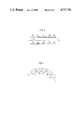
- FIG. 1 is a schematic plan view of a charged particle apparatus embodying features of the present invention
- FIG. 2 is a diagram illustrating the arrangement and magnetic field intensity distribution of air-core coils in the embodiment of FIG. 1;
- FIG. 3 is a schematic side view in section of another embodiment derived from the modification of the charged particle apparatus shown in FIG. 1;
- FIG. 4 is a schematic plan view of FIG. 3.
- FIG. 1 there is shown a storage ring 10 which is used as a light source for exposing work in the manufacture of very large scale integrated circuits (VLSIs), embodying the present invention.
- VLSIs very large scale integrated circuits
- a train of inflectors starting from a first inflector 2a through a seventh inflector 2g are arranged in sequence in an approximate circular arc in the area of introduction of electron beam 1 so that a round equilibrium orbit 3 for the electron beam is formed.
- the centers of curvature of the inflectors are located progressively inwardly toward the center of the equilibrium orbit 3.
- the introducing area is also provided with a rectangular bump electromagnet 6a, and first and second radio frequency cavities 7a, 7b are disposed along the equilibrium orbit 3 together with a fine adjustment bump electromagnet 6b.
- a point 9 on the magnetic field boundary 4 of the storage ring 10 touches a tangent line 5, with respect to which the electron beam 1 runs at a fixed angle ⁇ and passes through point 9 in the direction of a radius vector 8.
- Synchrotron orbital radiation emitted from part of the circular equilibrium orbit 3 passes through the gap between the fourth and fifth inflectors 2d, 2e, for example, to be utilized as intended.
- the electron beam 1 which is fed from an accelerator located upstream from the storage ring 10 is introduced at a fixed angle ⁇ , 30 degrees for example, with respect to the tangent line 5 and fed through the first to the seventh inflectors 2a-2g. It is further passed through the rectangular bump electromagnet 6a to render it parallel with the equilibrium orbit 3.
- the sectional center of the electron beam 1 then tends to slowly oscillate around the center of the equilibrium orbit 3. This oscillation is eliminated by the bump electromagnet 6b which reduces any angular deviation between the electron beam 1 and the equilibrium orbit 3 to zero. This occurs at the point where the center of the electron beam 1 initially crosses the equilibrium orbit 3; at a point having a weak focusing electromagnetic field distribution.
- the radiation loss of a synchrotron depends on the kinetic energy of the electron beam 1. Where it is about 800 MeV with the circular equilibrium orbit having a diameter of about 1.6 m, the loss will be approximately 45 KeV. To lengthen a quantum life sufficiently with such a high radiation loss it is necessary to produce a higher accelerating voltage in radio frequency cavities. This is sometimes difficult to achieve with a single radio frequency cavity. Taking this into consideration, the present embodiment utilizes the two such cavities 7a and 7b. Of course, there are cases in which a single cavity will perform the intended purposes.
- FIG. 2 shows the magnetic field distribution 17 of the storage ring 10 thus constructed and an example of the coil arrangement to form such field distribution.
- the abscissa 11 starting from the origin 13 coincides with the radius vector 8 and indicates the lateral position of the equilibrium orbit 3.
- the ordinate 12 represents the relative positional dimensions of the coils and the relative magnetic field intensity 17.
- the magnetic field of the storage ring 10 is built up of air-core coils, which can be replaced with either superconducting coils or normal conducting coils according to the required magnetic field strength and the diameter of the orbit 3.
- a positive magnetic field is formed inside the magnetic field boundary 4 shown in FIG. 1. It provides a weak focusing magnetic field of the known kind near the equilibrium orbit to prevent the horizontal and vertical dissipation of the electron beam, which serves a function equivalent to the quadrupole electromagnets in the conventional apparatus.
- the magnetic intensity is reduced to a negligible level by an appropriate magnetic shelter.
- the first through the seventh inflectors 2a-2g are, in contrast to conventional ones, disposed to form an approximate circular arc such that their centers of curvature are located progressively inwardly toward the center of the circular equilibrium orbit.
- the inflectors 2a through 2g shown in FIG. 1 are located within the magnetic field encompassing the center of the storage ring.
- the electric field applied by these inflectors formed by applying voltage between negative and positive electrodes, however, is oriented in a direction to increase the radius of curvature of the electron beam 1 on comparing with in case of no existing of inflectors. In this way the inflectors according to the present invention have the same function as that of the conventional inflectors.
- the beam 1 introduced at point 9 can be fed into the equilibrium orbit without an excessive bending by the magnetic field.
- the number of the inflectors will be selected depending upon the magnetic intensity of the storage ring 10 and the kinetic energy of the electron beam. Electron flux steadily circulating along the equilibrium orbit 3 will run for several hours to several tens of hours while emitting synchrotron orbital radiation (not shown) and with having lost energy consumed by the synchrotron radiation supplied through the first and second radio frequency cavities 7a and 7b.
- the electron beam thus circulating the orbit is under a vacuum of 10 -9 to 10 -11 torrs.
- FIGS. 3 and 4 show another embodiment in the concerned portion of the present invention which solves this problem.
- first pair of negative and positive electrodes 18a and 18b are disposed vertically flanking the equilibrium orbit 3 to remove the positive electrons from the beam running along the orbit.
- second through fifth pairs of negative and positive electrodes 19a and 19b to 22a and 22b are disposed in sequence.
- the construction of this embodiment is identical to the embodiment shown in FIG. 1 other than the provision of the electrode pairs. The operation of the modified embodiment will now be explained with reference to the first pair of electrodes 18a and 18b.
- first negative electrode 18a and the first positive electrode 18b a voltage of several kV for example is applied to form an electric field between them.
- positively charged particles will be accelerated toward the negative electrode 18a and negatively charged particles will be accelerated toward the positive electrode 18b.
- positive ions existing between the electrodes 18a and 18b in the electron flux have low kinetic energy, they are accelerated toward the first negative electrode 18a with their speed and direction depending on the distance between the electrodes 18a and 18b as well as their length. They then collide with the electrode 18a and are neutralized.
- the kinetic energy of each electron in the beam running between the electrodes 18a and 18b is very large compared with the energy the electrons obtain from the electric field formed by the electrodes 18a and 18b.
- the pair of negative and positive electrodes 18a and 18b installed along the orbit 3 will not adversely affect the stable movement of the electron beam but will be effective in removing the positive ions.
- plural pairs of negative and positive electrodes are required as shown in the figures for removing a considerable amount of ions accumulated in tens of thousands of electron beam circulations along the equilibrium orbit, however, the cumulative effect of the plural pairs of electrodes cannot be ignored.
- adjacent pairs of negative and positive electrodes are disposed in reversed polarity to each other.
- the second positive electrode 19b is disposed next to the first negative electrode 18a and the second negative electrode 19a is disposed next to the first positive electrode 18b; a stable electron beam circulation along the equilibrium orbit 3 is thus effected for a considerable number of cycles.
- the negative and positive electrodes in the above-mentioned embodiment may be composed of flat conductors, curved conductors, or plates in which insulated conductors are installed.
- electrodes having a mesh structure can be used as shown schematically for a portion of electrode 20a in FIG. 4.
- the inflectors 2a through 2g for introducing the electron beam 1 gradually into the equilibrium orbit 3 using an electric field have been described for the aforesaid embodiments, a system using a magnetic field such as generated by the bump electromagnet 6a can also be utilized.
- the number of inflectors is not limited to seven, and an inflector using an electric field can be used in place of the bump electromagnet 6a.
- the magnetic field for a storage ring formed by air-core coils as described can be replaced with iron-core electromagnets in the area near the equilibrium orbit 3 as is well known. Therefore, the present invention is not limited to a system using air-core coils.
- the storage ring can be equipped to implement both synchrotron and storage ring functions, in which case the intended purposes can be achieved with a lesser number of inflectors since the kinetic energy of an injected electron beam can be made much lower than the energy stored in the ring.
Landscapes
- Physics & Mathematics (AREA)
- Engineering & Computer Science (AREA)
- Plasma & Fusion (AREA)
- Spectroscopy & Molecular Physics (AREA)
- Particle Accelerators (AREA)
Applications Claiming Priority (4)
| Application Number | Priority Date | Filing Date | Title |
|---|---|---|---|
| JP60-158086 | 1985-07-19 | ||
| JP15808685A JPS6220300A (ja) | 1985-07-19 | 1985-07-19 | 荷電粒子装置 |
| JP60-163905 | 1985-07-26 | ||
| JP16390585A JPS6226797A (ja) | 1985-07-26 | 1985-07-26 | 荷電粒子装置 |
Publications (1)
| Publication Number | Publication Date |
|---|---|
| US4737726A true US4737726A (en) | 1988-04-12 |
Family
ID=26485333
Family Applications (1)
| Application Number | Title | Priority Date | Filing Date |
|---|---|---|---|
| US06/887,769 Expired - Lifetime US4737726A (en) | 1985-07-19 | 1986-07-21 | Charged particle beam storage and circulation apparatus |
Country Status (3)
| Country | Link |
|---|---|
| US (1) | US4737726A (de) |
| EP (1) | EP0209398B1 (de) |
| DE (1) | DE3681841D1 (de) |
Cited By (3)
| Publication number | Priority date | Publication date | Assignee | Title |
|---|---|---|---|---|
| US5587632A (en) * | 1994-09-05 | 1996-12-24 | National Laboratory For High Energy Physics | Injection apparatus both for positive and negative ions |
| RU2179379C2 (ru) * | 1999-07-12 | 2002-02-10 | Зубарев Андрей Вячеславович | Инфлектор |
| WO2011104079A1 (de) * | 2010-02-24 | 2011-09-01 | Siemens Aktiengesellschaft | Hf-resonatorkavität und beschleuniger |
Families Citing this family (2)
| Publication number | Priority date | Publication date | Assignee | Title |
|---|---|---|---|---|
| DE3938628C2 (de) * | 1988-11-24 | 1999-02-18 | Mitsubishi Electric Corp | Vorrichtung zum Speichern von geladenen Teilchen |
| JP2796071B2 (ja) * | 1994-11-16 | 1998-09-10 | 科学技術振興事業団 | 電子蓄積リングを用いた放射線発生方法及び電子蓄積リング |
Citations (1)
| Publication number | Priority date | Publication date | Assignee | Title |
|---|---|---|---|---|
| US3328708A (en) * | 1965-03-04 | 1967-06-27 | Bob H Smith | Method and apparatus for accelerating ions of any mass |
Family Cites Families (1)
| Publication number | Priority date | Publication date | Assignee | Title |
|---|---|---|---|---|
| DE3148100A1 (de) * | 1981-12-04 | 1983-06-09 | Uwe Hanno Dr. 8050 Freising Trinks | "synchrotron-roentgenstrahlungsquelle" |
-
1986
- 1986-07-18 DE DE8686305569T patent/DE3681841D1/de not_active Expired - Lifetime
- 1986-07-18 EP EP86305569A patent/EP0209398B1/de not_active Expired
- 1986-07-21 US US06/887,769 patent/US4737726A/en not_active Expired - Lifetime
Patent Citations (1)
| Publication number | Priority date | Publication date | Assignee | Title |
|---|---|---|---|---|
| US3328708A (en) * | 1965-03-04 | 1967-06-27 | Bob H Smith | Method and apparatus for accelerating ions of any mass |
Non-Patent Citations (2)
| Title |
|---|
| "Sor-Ring-An Electron Storage Ring Dedicated to Spectroscopy", by T. Miyahara et al, Particle Accelerators, vol. 7, No. 3, pp. 163-175, 1976. |
| Sor Ring An Electron Storage Ring Dedicated to Spectroscopy , by T. Miyahara et al, Particle Accelerators, vol. 7, No. 3, pp. 163 175, 1976. * |
Cited By (3)
| Publication number | Priority date | Publication date | Assignee | Title |
|---|---|---|---|---|
| US5587632A (en) * | 1994-09-05 | 1996-12-24 | National Laboratory For High Energy Physics | Injection apparatus both for positive and negative ions |
| RU2179379C2 (ru) * | 1999-07-12 | 2002-02-10 | Зубарев Андрей Вячеславович | Инфлектор |
| WO2011104079A1 (de) * | 2010-02-24 | 2011-09-01 | Siemens Aktiengesellschaft | Hf-resonatorkavität und beschleuniger |
Also Published As
| Publication number | Publication date |
|---|---|
| EP0209398B1 (de) | 1991-10-09 |
| DE3681841D1 (de) | 1991-11-14 |
| EP0209398A3 (en) | 1988-07-06 |
| EP0209398A2 (de) | 1987-01-21 |
Similar Documents
| Publication | Publication Date | Title |
|---|---|---|
| US3571642A (en) | Method and apparatus for interleaved charged particle acceleration | |
| CA1308808C (en) | Proton source | |
| US7466085B2 (en) | Cyclotron having permanent magnets | |
| US5117212A (en) | Electromagnet for charged-particle apparatus | |
| JPH11513528A (ja) | アイソクロナスサイクロトロンから荷電粒子を抽出する方法及びこの方法を応用する装置 | |
| KR19990022825A (ko) | 중첩 정적 및 시변자계를 생성하는 시스템 및 방법 | |
| KR20230111236A (ko) | 공진기, 선형 가속기 구성 및 토로이드형 공진기를갖는 이온 주입 시스템 | |
| TW463534B (en) | Method and system of reducing axial beam focusing | |
| US4694457A (en) | Methods of steering and focusing ion and electron beams | |
| US4737726A (en) | Charged particle beam storage and circulation apparatus | |
| EP0426861A1 (de) | Verfahren zur kühlung eines strahles geladener teilchen | |
| Dubniuk et al. | Radiation complex on the basis of helium ions linac | |
| US3459988A (en) | Cyclotron having charged particle and electron beams | |
| JP2004513495A (ja) | イオン注入装置のビームラインにおける中性子放射を抑止するための機構 | |
| US12096548B2 (en) | Drift tube electrode arrangement having direct current optics | |
| US6653640B2 (en) | Multichannel linear induction accelerator of charged particles | |
| US2904720A (en) | Ion accelerator | |
| JPH0552639B2 (de) | ||
| WO2018096648A1 (ja) | 加速器および粒子線照射装置 | |
| Adegun | Improvement of the efficiency and beam quality of the TRIUMF Charge State Booster | |
| KR102767673B1 (ko) | 양성자 이온원을 이용한 감마선 발생 장치 | |
| SU1011032A1 (ru) | Ионна ускорительна трубка | |
| JP2001052896A (ja) | 粒子加速・蓄積装置 | |
| US3492531A (en) | Non-uniform magnetic field type electron current generating device | |
| US3239707A (en) | Cyclotron ion source |
Legal Events
| Date | Code | Title | Description |
|---|---|---|---|
| AS | Assignment |
Owner name: MITSUBISHI DENKI KABUSHIKI KAISHA, 2-3, MARUNOUCHI Free format text: ASSIGNMENT OF ASSIGNORS INTEREST.;ASSIGNORS:UEDA, KOJU;MIZOTA, MANABU;NAKAMURA, SHIRO;AND OTHERS;REEL/FRAME:004823/0870 Effective date: 19860807 Owner name: MITSUBISHI DENKI KABUSHIKI KAISHA,JAPAN Free format text: ASSIGNMENT OF ASSIGNORS INTEREST;ASSIGNORS:UEDA, KOJU;MIZOTA, MANABU;NAKAMURA, SHIRO;AND OTHERS;REEL/FRAME:004823/0870 Effective date: 19860807 |
|
| STCF | Information on status: patent grant |
Free format text: PATENTED CASE |
|
| FPAY | Fee payment |
Year of fee payment: 4 |
|
| FEPP | Fee payment procedure |
Free format text: PAYOR NUMBER ASSIGNED (ORIGINAL EVENT CODE: ASPN); ENTITY STATUS OF PATENT OWNER: LARGE ENTITY |
|
| FPAY | Fee payment |
Year of fee payment: 8 |
|
| FPAY | Fee payment |
Year of fee payment: 12 |