US4741675A - Flow control system for a hydraulic pump - Google Patents
Flow control system for a hydraulic pump Download PDFInfo
- Publication number
- US4741675A US4741675A US06/892,555 US89255586A US4741675A US 4741675 A US4741675 A US 4741675A US 89255586 A US89255586 A US 89255586A US 4741675 A US4741675 A US 4741675A
- Authority
- US
- United States
- Prior art keywords
- fluid
- valve
- pump
- hydraulic
- control system
- Prior art date
- Legal status (The legal status is an assumption and is not a legal conclusion. Google has not performed a legal analysis and makes no representation as to the accuracy of the status listed.)
- Expired - Fee Related
Links
Images




Classifications
-
- F—MECHANICAL ENGINEERING; LIGHTING; HEATING; WEAPONS; BLASTING
- F04—POSITIVE - DISPLACEMENT MACHINES FOR LIQUIDS; PUMPS FOR LIQUIDS OR ELASTIC FLUIDS
- F04B—POSITIVE-DISPLACEMENT MACHINES FOR LIQUIDS; PUMPS
- F04B49/00—Control, e.g. of pump delivery, or pump pressure of, or safety measures for, machines, pumps, or pumping installations, not otherwise provided for, or of interest apart from, groups F04B1/00 - F04B47/00
- F04B49/22—Control, e.g. of pump delivery, or pump pressure of, or safety measures for, machines, pumps, or pumping installations, not otherwise provided for, or of interest apart from, groups F04B1/00 - F04B47/00 by means of valves
- F04B49/225—Control, e.g. of pump delivery, or pump pressure of, or safety measures for, machines, pumps, or pumping installations, not otherwise provided for, or of interest apart from, groups F04B1/00 - F04B47/00 by means of valves with throttling valves or valves varying the pump inlet opening or the outlet opening
Definitions
- the present invention relates generally to a hydraulic control system for delivering fluid to one or more fluid actuated devices and more particularly to a hydraulic control system for controlling the flow from a fixed displacement pump to provide the desired amount of output flow when the system is in its working mode and to provide only a minimal amount of lubricating flow when the system is in its non-working mode.
- a fixed displacement hydraulic pump is mounted on mobile equipment and is driven by the same prime mover which provides the power for the piece of mobile equipment.
- the fixed displacement pump provides hydraulic fluid under pressure to various fluid actuated devices which are typically utilized only a small portion of the time that the vehicle prime mover, which is typically an internal combustion engine, is operating. It is well known that unless means are provided for disengaging a pump from the vehicle engine two undesirable effects occur. First, engine power is wasted resulting in less economical operation of the engine and, second, the hydraulic circuit becomes a source of significant noise, especially at high engine speeds.
- a hydraulic control system having a supply of low pressure hydraulic fluid and a hydraulic pump having a fluid inlet and a fluid outlet through which fluid is delivered at a high operating pressure when the pump is pumping at its capacity.
- a valve is placed in fluid communication with the supply of hydraulic fluid and the pump fluid inlet for permitting fluid communication between the supply of hydraulic fluid and the pump fluid inlet when in one mode of operation and for substantially preventing fluid communication between the supply of hydraulic fluid and the pump fluid when in a second mode of operation a control means prevents the valve from assuming its second mode of operation until the magnitude of the pressure at the pump fluid outlet is below a predetermined pressure.
- the predetermined pressure is set to be substantially below the pump operating pressure.
- the valve mounted in the fluid inlet is adapted to rotate therein from a first position in which fluid is free to flow through the fluid inlet to a second position in which the valve substantially prevents the flow of fluid through the inlet.
- Hydraulically controlled means are provided for rotating the valve back and forth between the first and second positions.
- An object of the present invention is the provision of a hydraulic control system for switching the output of a hydraulic pump between a first mode in which the system operates at a low level of flow and pressure to a second mode in which the system operates at maximum flow and pressure levels.
- Another object of the present invention is the provision of a hydraulic control system for controlling the output of a hydraulic pump in a quiet and efficient manner.
- a further object of the present invention is the provision of a hydraulic control system for controlling the output flow of a hydraulic pump which is compactly designed so as to occupy a minimum amount of space.
- Another object of the present invention is the provision of a hydraulic control system for controlling the output flow of a hydraulic pump which results in improved component life.
- Yet another object of the present invention is the provision of a hydraulic control system for controlling the output flow of a hydraulic pump which is relatively easy and inexpensive to manufacture.
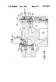
- FIG. 1 is a graphic diagram of the hydraulic control system of the present invention
- FIG. 2 shows a side view of the hydraulic control system of the present invention
- FIG. 3A shows a partial cross-sectional view taken along Line 3--3 of FIG. 2;
- FIG. 3B shows one form of gear pump mechanism suitable for use with the hydraulic control system of the present invention taken in partial cross-section along Line 3B--3B of FIG. 3A.
- FIG. 3C shows a second embodiment of the hydraulic control system shown in FIG. 3A;
- FIG. 3D shows a third embodiment of the hydraulic control system shown in FIG. 3A;
- FIG. 4 shows a partial cross-sectional view taken along Line 4--4 of FIG. 3A.
- FIG. 5 shows a partial cross-sectional view taken along Line 5--5 of FIG. 3A.
- a hydraulic control system 10 for delivering fluid to one or more fluid actuated devices (not shown).
- the system includes a pump 12, which is preferably a gear pump, having a fluid inlet adapted to be placed in fluid communication with a supply of low pressure hydraulic fluid such as a reservoir 14.
- the pump 12 is designed to deliver fluid through its fluid outlet at a high operating pressure when the pump is pumping fluid at its capacity.
- a two position valve 16 is connected in fluid communication with the reservoir 14 and the pump fluid inlet and is preferably located in the pump fluid inlet.
- the valve 16 is normally spring biased to a first position 18 in which the valve 16 substantially prevents fluid communication between the reservoir 14 and the inlet of pump 12 since the amount of flow is limited by an orifice or restriction 20.
- valve 16 In response to a control pressure signal on line 22 having a magnitude above a predetermined pressure, the valve 16 overcomes its spring bias and is shifted into position 24 permitting unrestricted fluid communication between the reservoir 14 and the fluid inlet of pump 12.
- a line 26 places the pump bearings and seals in fluid communication with the reservoir 14 and also assures that the portion of the valve 16 which is spring biased to the closed position is maintained at reservoir pressure.
- variable orifice 28 The output of pump 12 flows through a variable orifice 28 and a check valve 30 to a fluid outlet port 32 adapted to be connected to one or more fluid actuated devices.
- the variable orifice 28 is preferably in the form of a needle type valve and the check valve 30 is designed to introduce a small pressure drop into the system as will be more particularly described in connection with FIG. 3. In the event that the hydraulic circuitry downstream of port 32 provides an adequate amount of back pressure, the check valve 30 may be eliminated from the circuit.
- the variable orifice 28 is part of a control circuit for generating a control pressure signal as will be discussed further herein.
- the control circuit includes a signal line 34 connected to the low pressure side of the orifice 28.
- the signal line 34 then passes through a fixed orifice 36 to be distributed to three points in the system.
- Signal line 22 applies the control pressure signal thus derived, to the valve 16 to overcome the spring bias of that valve and permit fluid communication between the reservoir 14 and the fluid inlet of pump 12 when the magnitude of the control pressure signal exceeds a predetermined pressure.
- the valve 16 is spring biased to the closed position wherein fluid communication between the reservoir 14 and the fluid inlet of pump 12 is substantially prevented since it is limited to the amount of flow through orifice 20.
- Signal line 34 is also in communication with a signal line 38 delivered to valve 40 which is typically actuated by the operator.
- the valve 40 is preferably electrically actuated but could also be actuated pneumatically, hydraulically or manually.
- the valve 40 is a two position valve which is normally spring biased to an open position 42 which permits the flow of fluid in signal line 38 to pass through the valve 40 to a line 44 in communication with reservoir 14.
- a signal line 48 is in fluid communication with the signal line 34, the signal line 38, the signal line 22 and a bypass valve 50.
- the bypass valve 50 is in fluid communication with the fluid outlet of pump 12 and the reservoir 14 and is responsive to the difference between the magnitudes of the pressures of the fluid in the pump fluid outlet and the signal line 48 for diverting the flow of fluid from the pump fluid outlet to the reservoir.
- the system also includes an over pressure relief valve 52 located downstream of the check valve 30 for placing the output of pump 12 and any fluid actuated devices connected to port 32 in fluid communication with reservoir 14 in the event the pressure at port 32 exceeds a predetermined limit.
- the service port 32 is connected to at least one fluid actuated device (not shown).
- the electrically actuated valve 40 is unenergized and is therefore spring biased to the open position 42 shown in FIG. 1.
- the pump 12 is mechanically connected by an input shaft 54 to a prime mover, usually an internal combustion engine (also not shown). Since the signal line 22 is in fluid communication with the reservoir 14, the inlet valve 16 is spring biased to its closed position 18. Likewise the signal on line 48 is in fluid communication with reservoir 14, but since the output from pump 12 is quite small with the inlet valve 16 in its closed position, the bypass valve 50 is also spring biased to its closed position.
- the relatively small amount of oil drawn by the pump 12 through the inlet orifice 20 in valve 16 is pumped through the pump fluid outlet through variable orifice 28 and along line 34 through fixed orifice 36, signal line 38, position 42 of valve 40 and line 44 to reservoir 14.
- This small amount of pump flow is utilized as cooling and lubricating flow for the pump when no fluid is required for the fluid actuated device or devices coupled to port 32.
- This low level of flow through the system at low pressure results in relatively quiet operation.
- valve 40 When it is desired to provide output fluid at port 32, the operator energizes valve 40 causing it to overcome its spring bias and be placed in the closed position 46.
- the low level of flow from pump 12 is now directed to check valve 30 which is designed to introduce a sufficient amount of back pressure into the system before opening to raise the pressure on signal line 22 to a sufficient level to cause valve 16 to overcome its spring bias and be forced into the open position 24. If check valve 30 is not utilized in the system, there must be sufficient back pressure inherent in the circuit beyond port 32 to provide this effect. It should be noted that valve 16 thus opens while the system is operating at relatively low pressures.
- the pump 12 is now placed in full fluid communication with reservoir 14 which permits the pump to assume its full flow capacity.
- valve 40 When it is desired to discontinue activation of the fluid actuated device or devices connected to port 32, the operator deenergizes valve 40 which then once again assumes its open position 42.
- the flow path from pump 12 through variable orifice 28, line 34, fixed orifice 36, line 38, valve 40 and line 44 to reservoir 14 is now once again reopened.
- the flow across variable orifice 28 and fixed orifice 36 creates a significant differential pressure between signal line 48 and the pump output pressure.
- This differential pressure is sensed by bypass valve 50 which is now biased to its open position placing the output from pump 12 in direct fluid communication with reservoir 14 thereby reducing the discharge pressure at the output of pump 12.
- This relatively low pressure for opening and closing valve 16 should be contrasted to the normal operating pressure of a typical system of 2000 to 3000 pounds per square inch.
- the bypass valve 50 will be biased to its open position when the differential pressure between signal line 48 and the output of pump 12 exceeds 40 pounds per square inch.
- the bypass valve 50 will open prior to the pressure in signal lines 48 and 22 declining to the threshold pressure of approximately 25 pounds per square inch necessary to close valve 16.
- valve 16 will be prevented from closing until the pump output pressure drops below approximately 65 pounds per square inch.
- the pressure in control signal line 22 rises with the pump output pressure and opens valve 16 before the pump output pressure exceeds the threshold pressure of approximately 25 pounds per square inch.
- the pump output pressure is limited to less than the threshold pressure of approximately 25 pounds per square inch. Further, it should be noted that if a check valve 30 is provided as shown, it should be designed to introduce a back pressure of 30 pounds per square inch into the system before opening in order to produce the necessary control signal on line 22.
- a housing 60 includes a cavity 62 therein for receiving a pumping mechanism 64.
- the pumping mechanism 64 is preferably of the gear pump type and includes a pair of rotating shafts 54 and 68, with shaft 54 coupled to a prime mover to drive the pumping mechanism.
- the gear pump mechanism includes a plurality of bearings 70 supporting the rotating shafts 54 and 68.
- the housing 60 has a fluid inlet 72 and a fluid outlet 74 contained therein. The fluid inlet and fluid outlet are separated from each other in a known fashion by the use of seals (not shown) and by the gear mechanism shown in FIG.
- the fluid inlet 72 includes a portion 76 having a circular cross-section.
- the valve 16 is mounted in the fluid inlet and is adapted to rotate therein from a first position in which fluid is free to flow through the fluid inlet to a second position in which the valve 16 substantially prevents the flow of fluid through the fluid inlet.
- the valve 16 is preferably a butterfly type valve having a disc shaped valve member 78 having a sufficient diameter to substantially prevent the flow of fluid through the portion of the inlet 76 when the valve 16 is in its closed position.
- the desired amount of cooling and lubricating flow through the pump 12 may be obtained by merely providing a sufficient amount of clearance between the outside edge of the disc shaped member 78 and the walls of portion 76 to provide the desired amount of flow.
- An alternative way of providing the desired amount of lubricating flow is shown in FIG. 3C wherein one or more orifices 20 are provided in the disc shaped member 78 in addition to or instead of providing clearance around the edge of the member 78.
- the housing 60 is further provided with a bearing and seal drain cavity 80 in fluid communication with the inlet by means of passageways 82 and 84 and a bore 86 to establish the aforementioned drain line 16.
- the housing 60 may include an orifice 88 located downstream of the valve 16 for placing the drain passageway 82 in fluid communication with the inlet 72. This alternative embodiment is shown in FIG. 3D.
- the valve 16 further includes a pivot rod 90 extending diametrically across the inlet portion 76 and adapted to rotate therein.
- the pivot rod 90 includes a flattened portion 92 to which the disc shaped valve member 78 is affixed, preferably by means of machine screws 94.
- the housing 60 further includes a passageway 22 for delivering the control pressure signal mentioned in connection with the description of FIG. 1.
- a linear actuator 100 is adapted to reciprocate in a linear direction in bore 86 in response to the magnitude of the control signal received from passageway 22.
- Motion translating means 102 are connected to the valve 16 for converting the linear movement of the linear actuator 100 to rotational movement thereby causing the valve 16 to rotate to its open and closed positions in response to the magnitude of the control signal.
- the motion translating means includes a bore 104 in the end of the linear actuator 100 facing the pivot rod 90.
- the linear actuator 100 is spring biased away from the end of pivot rod 90 by a spring 106 seated at one end against the housing 60 in the bottom of bore 86 and at the other end against shoulder 108 on linear actuator 100.
- the bore 104 includes a pair of helical guides preferably in the form of helical slots 110 in the wall thereof, with each of the helical guides being spaced 180° apart.
- the pivot rod 90 includes a pair of projections 112 spaced 180° apart on one end thereof, preferably formed by inserting a pin through a hole in the end of rod 90.
- the projections 112 are adapted to ride in the helical slots 110 as the linear actuator 100 reciprocates to thereby impart rotational motion to the pivot rod 90 to open and close valve 16.
- the linear actuator 100 acts as a piston assembly which is generally cylindrical in shape and is substantially symmetrical about a central axis 114.
- the piston includes a second small bore 116 in its other end.
- the bore 116 is parallel to but displaced from the central axis 114.
- a plug 118 closes the bore 86 and a pin 120 is affixed to the plug 118 and extends therefrom into the bore 116.
- the diameter of the pin 120 is slightly smaller than the diameter of the bore 116 to thereby enable the pin to slide freely in the bore 116 as the piston assembly reciprocates.
- the action of the pin 120 prevents the linear actuator 100 from rotating within bore 86.
- the control passageway 22 intersects the bore 86 to thereby provide fluid communication between the passageway 22 and the bore 86 providing hydraulically controlled means for rotating the valve 16 between its open and closed positions.
- the fluid outlet passageway 74 of pump 12 intersects a passageway 122 of reduced diameter which in combination with a needle valve 123 forms a variable orifice 28.
- the needle valve 123 includes a body portion 124 and a conical nose 126 whose position may be adjusted by means of a threaded rod 128 attached to the body portion of the valve 123.
- the threaded rod 128 is typically set at a given position to obtain a desired differential pressure between fluid outlet 74 and signal line 34 when the pump is operating at its capacity.
- a cap 130 is then fitted over the rod 128 to prevent inadvertent adjustment of the rod 128.
- the check valve 30 is spring biased by a spring 132 and is in sliding engagement with the needle valve 123 so as to be free to reciprocate thereon.
- the port 32 is in turn connected to a passageway 134 which is separated from passageway 44 to tank by relief valve 52 as is clearly shown in FIG. 5.
- variable orifice 28 also downstream of variable orifice 28 is passageway 34 leading to a restricted passageway 36 which forms the fixed orifice referred to earlier.
- passageway 48 Connected to the fixed orifice 36 is a passageway 48 leading to bypass valve 50 and passageway 38 in turn connected to electrically actuated valve 40.
- valve 16 opens and closes at relatively low pressures and opens and closes gradually because of its rotating action results in a quiet and efficiently operating system.
- the valve 16 fits neatly within the system housing without significantly adding to the housing size resulting in a compact design occupying a minimum amount of space. Additionally, the smooth operation of the valve 16 will contribute to improved component life. Finally, the system of the present invention is relatively easy and inexpensive to manufacture.
Landscapes
- Engineering & Computer Science (AREA)
- Mechanical Engineering (AREA)
- General Engineering & Computer Science (AREA)
- Details And Applications Of Rotary Liquid Pumps (AREA)
- Control Of Positive-Displacement Pumps (AREA)
- Fluid-Pressure Circuits (AREA)
Priority Applications (2)
| Application Number | Priority Date | Filing Date | Title |
|---|---|---|---|
| US06/892,555 US4741675A (en) | 1986-08-04 | 1986-08-04 | Flow control system for a hydraulic pump |
| EP87110878A EP0255681A3 (de) | 1986-08-04 | 1987-07-27 | Förderstromregelungssystem für eine hydraulische Pumpe |
Applications Claiming Priority (1)
| Application Number | Priority Date | Filing Date | Title |
|---|---|---|---|
| US06/892,555 US4741675A (en) | 1986-08-04 | 1986-08-04 | Flow control system for a hydraulic pump |
Publications (1)
| Publication Number | Publication Date |
|---|---|
| US4741675A true US4741675A (en) | 1988-05-03 |
Family
ID=25400125
Family Applications (1)
| Application Number | Title | Priority Date | Filing Date |
|---|---|---|---|
| US06/892,555 Expired - Fee Related US4741675A (en) | 1986-08-04 | 1986-08-04 | Flow control system for a hydraulic pump |
Country Status (2)
| Country | Link |
|---|---|
| US (1) | US4741675A (de) |
| EP (1) | EP0255681A3 (de) |
Cited By (15)
| Publication number | Priority date | Publication date | Assignee | Title |
|---|---|---|---|---|
| US4898333A (en) * | 1988-08-30 | 1990-02-06 | H.Y.O., Inc. | Hydraulic system for use with snow-ice removal vehicles |
| USRE33835E (en) * | 1988-08-30 | 1992-03-03 | H.Y.O., Inc. | Hydraulic system for use with snow-ice removal vehicles |
| US5192196A (en) * | 1991-03-11 | 1993-03-09 | Ford Motor Company | Flow control orifice for parallel flow fluid supply to power steering gear |
| US5363649A (en) * | 1989-12-18 | 1994-11-15 | Dana Corporation | Hydraulic dry valve control apparatus |
| US6099264A (en) * | 1998-08-27 | 2000-08-08 | Itt Manufacturing Enterprises, Inc. | Pump controller |
| US6390072B1 (en) | 2000-05-30 | 2002-05-21 | Robert H. Breeden | Pump assembly |
| US6427663B1 (en) | 2000-12-08 | 2002-08-06 | Robert H. Breeden | Inlet throttle pump assembly for diesel engine and method |
| US6622706B2 (en) | 2000-05-30 | 2003-09-23 | Robert H. Breeden | Pump, pump components and method |
| US6679741B2 (en) * | 2000-05-09 | 2004-01-20 | Bombardier Motor Corporation Of America | Propulsion system having means dedicated for driving accessories in a boat |
| US20040101420A1 (en) * | 2002-11-18 | 2004-05-27 | Breeden Robert H. | Solenoid regulated pump assembly |
| US6755625B2 (en) | 2002-10-07 | 2004-06-29 | Robert H. Breeden | Inlet throttle valve |
| US7025044B1 (en) | 2003-07-16 | 2006-04-11 | R. H. Sheppard Co., Inc. | Pump assembly and method |
| US20130081718A1 (en) * | 2011-10-03 | 2013-04-04 | Fernando Ubidia | Dosing pump system |
| US10913648B2 (en) | 2016-01-04 | 2021-02-09 | Micro Infinity Flow, Llc | Motor and pump system |
| US20220403848A1 (en) * | 2021-06-18 | 2022-12-22 | Eaton Intelligent Power Limited | Safeguard for fuel pump |
Families Citing this family (4)
| Publication number | Priority date | Publication date | Assignee | Title |
|---|---|---|---|---|
| DE58901878D1 (de) * | 1988-03-08 | 1992-08-27 | Teves Gmbh Alfred | Bremsanlage. |
| DE3935325C1 (de) * | 1989-10-24 | 1991-05-23 | Mercedes-Benz Aktiengesellschaft, 7000 Stuttgart, De | |
| EP1914614B1 (de) * | 2006-09-28 | 2012-08-15 | Taichi Inada | Proportional-Druckregelventil |
| US10933186B2 (en) | 2016-11-22 | 2021-03-02 | Bayer Healthcare Llc | System and method for delivering a fluid with a consistent total volumetric flowrate |
Citations (22)
| Publication number | Priority date | Publication date | Assignee | Title |
|---|---|---|---|---|
| US822276A (en) * | 1902-11-29 | 1906-06-05 | Gen Electric | Pressure-regulated supply-valve. |
| US1345902A (en) * | 1917-09-07 | 1920-07-06 | Packard Motor Car Co | Pump for motor-vehicles |
| US1663647A (en) * | 1927-02-07 | 1928-03-27 | Alanson P Brush | Energy-storage unit |
| CA336303A (en) * | 1933-10-10 | The Heil Co. | Hoist mechanism | |
| US2118180A (en) * | 1936-02-05 | 1938-05-24 | Ferguson Henry George | Tractor for agricultural implements |
| US2433220A (en) * | 1944-10-20 | 1947-12-23 | New York Air Brake Co | Pressure control for pumps |
| CA529652A (en) * | 1956-08-28 | G. Kopp Lester | Tractor hydraulic systems | |
| CA622244A (en) * | 1961-06-20 | Czarnocki Witold | Hydraulic systems for tractors | |
| US3050004A (en) * | 1956-03-19 | 1962-08-21 | Bochumer Eisen Heintzmann | Valve gear for fluid pressure pumps |
| US3449911A (en) * | 1966-09-06 | 1969-06-17 | Paul W Schlosser | Power transfer system |
| US3482768A (en) * | 1968-02-28 | 1969-12-09 | Gardner Denver Co | Compressor control system |
| GB1232757A (de) * | 1968-09-13 | 1971-05-19 | ||
| GB1259167A (de) * | 1968-02-03 | 1972-01-05 | ||
| US3864059A (en) * | 1972-07-24 | 1975-02-04 | Sargent Industries | Noise reduction apparatus and method |
| US3873239A (en) * | 1971-10-22 | 1975-03-25 | Arthur A Jamieson | Compressor control |
| US3935917A (en) * | 1974-10-18 | 1976-02-03 | Tyrone Hydraulics, Inc. | Hydraulic pump control system |
| US4118149A (en) * | 1976-02-05 | 1978-10-03 | Hytec Ab | Output regulation in hydraulic and hydropneumatic systems |
| US4138204A (en) * | 1976-02-10 | 1979-02-06 | Bendiberica S.A. | Gear pump |
| US4171188A (en) * | 1976-08-03 | 1979-10-16 | Chicago Pneumatic Tool Company | Rotary air compressors with intake valve control and lubrication system |
| US4237926A (en) * | 1979-01-29 | 1980-12-09 | Caterpillar Tractor Co. | Fluid flow shutoff valve |
| US4345881A (en) * | 1980-01-31 | 1982-08-24 | Sundins Fabriker Ab | Close-off valve for suction pipes in hydraulic pumps |
| US4406589A (en) * | 1980-02-29 | 1983-09-27 | Tokico Ltd. | Compressor |
Family Cites Families (1)
| Publication number | Priority date | Publication date | Assignee | Title |
|---|---|---|---|---|
| DE3509856A1 (de) * | 1984-03-29 | 1985-10-10 | Zahnradfabrik Friedrichshafen Ag, 7990 Friedrichshafen | Hydraulikanlage fuer fahrzeuge |
-
1986
- 1986-08-04 US US06/892,555 patent/US4741675A/en not_active Expired - Fee Related
-
1987
- 1987-07-27 EP EP87110878A patent/EP0255681A3/de not_active Withdrawn
Patent Citations (24)
| Publication number | Priority date | Publication date | Assignee | Title |
|---|---|---|---|---|
| CA336303A (en) * | 1933-10-10 | The Heil Co. | Hoist mechanism | |
| CA529652A (en) * | 1956-08-28 | G. Kopp Lester | Tractor hydraulic systems | |
| CA622244A (en) * | 1961-06-20 | Czarnocki Witold | Hydraulic systems for tractors | |
| US822276A (en) * | 1902-11-29 | 1906-06-05 | Gen Electric | Pressure-regulated supply-valve. |
| US1345902A (en) * | 1917-09-07 | 1920-07-06 | Packard Motor Car Co | Pump for motor-vehicles |
| US1663647A (en) * | 1927-02-07 | 1928-03-27 | Alanson P Brush | Energy-storage unit |
| US2118180A (en) * | 1936-02-05 | 1938-05-24 | Ferguson Henry George | Tractor for agricultural implements |
| US2433220A (en) * | 1944-10-20 | 1947-12-23 | New York Air Brake Co | Pressure control for pumps |
| US3050004A (en) * | 1956-03-19 | 1962-08-21 | Bochumer Eisen Heintzmann | Valve gear for fluid pressure pumps |
| US3449911A (en) * | 1966-09-06 | 1969-06-17 | Paul W Schlosser | Power transfer system |
| US3449911B1 (de) * | 1966-09-06 | 1986-10-14 | ||
| GB1259167A (de) * | 1968-02-03 | 1972-01-05 | ||
| US3482768A (en) * | 1968-02-28 | 1969-12-09 | Gardner Denver Co | Compressor control system |
| GB1232757A (de) * | 1968-09-13 | 1971-05-19 | ||
| US3873239A (en) * | 1971-10-22 | 1975-03-25 | Arthur A Jamieson | Compressor control |
| US3864059A (en) * | 1972-07-24 | 1975-02-04 | Sargent Industries | Noise reduction apparatus and method |
| US3935917A (en) * | 1974-10-18 | 1976-02-03 | Tyrone Hydraulics, Inc. | Hydraulic pump control system |
| US3935917B1 (de) * | 1974-10-18 | 1987-06-09 | ||
| US4118149A (en) * | 1976-02-05 | 1978-10-03 | Hytec Ab | Output regulation in hydraulic and hydropneumatic systems |
| US4138204A (en) * | 1976-02-10 | 1979-02-06 | Bendiberica S.A. | Gear pump |
| US4171188A (en) * | 1976-08-03 | 1979-10-16 | Chicago Pneumatic Tool Company | Rotary air compressors with intake valve control and lubrication system |
| US4237926A (en) * | 1979-01-29 | 1980-12-09 | Caterpillar Tractor Co. | Fluid flow shutoff valve |
| US4345881A (en) * | 1980-01-31 | 1982-08-24 | Sundins Fabriker Ab | Close-off valve for suction pipes in hydraulic pumps |
| US4406589A (en) * | 1980-02-29 | 1983-09-27 | Tokico Ltd. | Compressor |
Cited By (20)
| Publication number | Priority date | Publication date | Assignee | Title |
|---|---|---|---|---|
| USRE33835E (en) * | 1988-08-30 | 1992-03-03 | H.Y.O., Inc. | Hydraulic system for use with snow-ice removal vehicles |
| US4898333A (en) * | 1988-08-30 | 1990-02-06 | H.Y.O., Inc. | Hydraulic system for use with snow-ice removal vehicles |
| US5363649A (en) * | 1989-12-18 | 1994-11-15 | Dana Corporation | Hydraulic dry valve control apparatus |
| US5192196A (en) * | 1991-03-11 | 1993-03-09 | Ford Motor Company | Flow control orifice for parallel flow fluid supply to power steering gear |
| US6099264A (en) * | 1998-08-27 | 2000-08-08 | Itt Manufacturing Enterprises, Inc. | Pump controller |
| US6679741B2 (en) * | 2000-05-09 | 2004-01-20 | Bombardier Motor Corporation Of America | Propulsion system having means dedicated for driving accessories in a boat |
| US6390072B1 (en) | 2000-05-30 | 2002-05-21 | Robert H. Breeden | Pump assembly |
| US6460510B1 (en) | 2000-05-30 | 2002-10-08 | Robert H. Breeden | Pump assembly and method |
| US6622706B2 (en) | 2000-05-30 | 2003-09-23 | Robert H. Breeden | Pump, pump components and method |
| US6662784B1 (en) | 2000-05-30 | 2003-12-16 | Robert H. Breeden | Pump assembly, valve and method |
| US6427663B1 (en) | 2000-12-08 | 2002-08-06 | Robert H. Breeden | Inlet throttle pump assembly for diesel engine and method |
| US6755625B2 (en) | 2002-10-07 | 2004-06-29 | Robert H. Breeden | Inlet throttle valve |
| US20040101420A1 (en) * | 2002-11-18 | 2004-05-27 | Breeden Robert H. | Solenoid regulated pump assembly |
| US7025044B1 (en) | 2003-07-16 | 2006-04-11 | R. H. Sheppard Co., Inc. | Pump assembly and method |
| US20130081718A1 (en) * | 2011-10-03 | 2013-04-04 | Fernando Ubidia | Dosing pump system |
| US9234512B2 (en) * | 2011-10-03 | 2016-01-12 | Tandem Technologies, Llc | Dosing pump system |
| US11965496B2 (en) | 2011-10-03 | 2024-04-23 | Fernando A. Ubidia | Dosing pump system |
| US10913648B2 (en) | 2016-01-04 | 2021-02-09 | Micro Infinity Flow, Llc | Motor and pump system |
| US12139389B2 (en) | 2016-01-04 | 2024-11-12 | Micro Infinity Flow Llc | Motor and pump system |
| US20220403848A1 (en) * | 2021-06-18 | 2022-12-22 | Eaton Intelligent Power Limited | Safeguard for fuel pump |
Also Published As
| Publication number | Publication date |
|---|---|
| EP0255681A2 (de) | 1988-02-10 |
| EP0255681A3 (de) | 1990-02-07 |
Similar Documents
| Publication | Publication Date | Title |
|---|---|---|
| EP0255681A2 (de) | Förderstromregelungssystem für eine hydraulische Pumpe | |
| US4403924A (en) | Method and device for regulating the output of diaphragm pumps | |
| US3694105A (en) | Fluid pressure system | |
| US4276960A (en) | Oil distributing means | |
| JPH01257712A (ja) | 液圧駆動式冷却ファンの制御装置 | |
| KR20120006977A (ko) | 직접 제어 선형 가변 베인펌프 | |
| JP3032550B2 (ja) | トランスミッションのオイル液位を制御する装置と潤滑装置 | |
| US3935917A (en) | Hydraulic pump control system | |
| US4013093A (en) | Hydraulic valves | |
| US3753627A (en) | Pump bypass liquid control | |
| US5609474A (en) | Gear pump | |
| US3288166A (en) | Accumulator system | |
| US2918826A (en) | Control device | |
| US3650643A (en) | Fluid pump and delivery system | |
| KR100278186B1 (ko) | 유압 펌프용 유동 제어 장치 | |
| US4746276A (en) | Gear pump having conditional dry valve closure structure | |
| US5133186A (en) | Device for controlling the pressure in a hydraulic pressure system | |
| GB1171707A (en) | Improved Multiple Pump Assembly | |
| US3901032A (en) | Reversible hydrostatic transmission | |
| US5013220A (en) | Oil pump having regulator valve isolated from dynamic pressure of pumped oil | |
| US3496875A (en) | Hydraulic pump | |
| US20060254269A1 (en) | Power regulating device | |
| US2992532A (en) | Control device | |
| JPS62135691A (ja) | 冷却または加熱ポンプ装置用の調整装置 | |
| US3241746A (en) | Compressor lubricant equalizing pump |
Legal Events
| Date | Code | Title | Description |
|---|---|---|---|
| AS | Assignment |
Owner name: GENERAL SIGNAL CORPORATION, A CORP OF NY. Free format text: ASSIGNMENT OF ASSIGNORS INTEREST.;ASSIGNOR:BOWDEN, CHARLES J.;REEL/FRAME:004601/0865 Effective date: 19860728 Owner name: GENERAL SIGNAL CORPORATION, A CORP OF NY., STATELE Free format text: ASSIGNMENT OF ASSIGNORS INTEREST;ASSIGNOR:BOWDEN, CHARLES J.;REEL/FRAME:004601/0865 Effective date: 19860728 |
|
| AS | Assignment |
Owner name: CONTINENTAL ILLINOIS NATIONAL BANK AND TRUST COMPA Free format text: SECURITY INTEREST;ASSIGNOR:ICM ACQUISITIONS, INC., A CORP. OF DE;REEL/FRAME:005156/0501 Effective date: 19870911 |
|
| AS | Assignment |
Owner name: ICM ACQUISITIONS, INC., A DE. CORP. Free format text: ASSIGNMENT OF ASSIGNORS INTEREST.;ASSIGNOR:GENERAL SIGNAL CORPORATION, A NY CORP.;REEL/FRAME:004855/0124 Effective date: 19870911 Owner name: HYDRECO, INC. Free format text: CHANGE OF NAME;ASSIGNOR:ICM ACQUISTIONS INC.;REEL/FRAME:004854/0821 Effective date: 19870910 |
|
| REMI | Maintenance fee reminder mailed | ||
| LAPS | Lapse for failure to pay maintenance fees | ||
| AS | Assignment |
Owner name: MAGNA-POW'R, INC., A CORPORATION OF IA, ILLINOIS Free format text: ASSIGNMENT OF ASSIGNORS INTEREST.;ASSIGNOR:HYDRECO, INC., A DE CORP.;REEL/FRAME:006101/0598 Effective date: 19920430 Owner name: MAGNA-POW'R, INC., A CORPORATION OF IA, ILLINOIS Free format text: ASSIGNMENT OF ASSIGNORS INTEREST.;ASSIGNOR:CONTINENTAL BANK N.A.;REEL/FRAME:006101/0604 Effective date: 19920430 |
|
| AS | Assignment |
Owner name: MAGNA-POW'R, INC. Free format text: ASSIGNMENT OF ASSIGNORS INTEREST.;ASSIGNOR:HYDRECO, INC.;REEL/FRAME:006298/0715 Effective date: 19920430 Owner name: MAGNA-POW'R, INC. Free format text: ASSIGNMENT OF ASSIGNORS INTEREST.;ASSIGNOR:CONTINENTAL BANK N.A.;REEL/FRAME:006298/0721 Effective date: 19920430 Owner name: CONTINENTAL BANK N.A. Free format text: SECURITY INTEREST;ASSIGNOR:MAGNA-POW'R, INC.;REEL/FRAME:006298/0727 Effective date: 19920430 |
|
| AS | Assignment |
Owner name: CONTINENTAL BANK N.A. Free format text: AMENDMENT TO SECURITY AGREEMENT;ASSIGNOR:MAGNA-POW'R, INC. A CORP. OF IA;REEL/FRAME:006167/0524 Effective date: 19920624 |
|
| FP | Lapsed due to failure to pay maintenance fee |
Effective date: 19920503 |
|
| AS | Assignment |
Owner name: LASALLE NATIONAL BANK, ILLINOIS Free format text: PATENT, TRADEMARK AND MORTGAGE LICENSE;ASSIGNOR:MAGNA-POW'ER, INC.;REEL/FRAME:008098/0419 Effective date: 19950427 |
|
| STCH | Information on status: patent discontinuation |
Free format text: PATENT EXPIRED DUE TO NONPAYMENT OF MAINTENANCE FEES UNDER 37 CFR 1.362 |