US4743124A - Anti-friction bearing - Google Patents
Anti-friction bearing Download PDFInfo
- Publication number
- US4743124A US4743124A US06/893,195 US89319586A US4743124A US 4743124 A US4743124 A US 4743124A US 89319586 A US89319586 A US 89319586A US 4743124 A US4743124 A US 4743124A
- Authority
- US
- United States
- Prior art keywords
- bearing
- bearing member
- load
- main body
- rows
- Prior art date
- Legal status (The legal status is an assumption and is not a legal conclusion. Google has not performed a legal analysis and makes no representation as to the accuracy of the status listed.)
- Expired - Lifetime
Links
- 239000000314 lubricant Substances 0.000 claims description 52
- 238000007789 sealing Methods 0.000 claims description 43
- 238000009826 distribution Methods 0.000 claims description 23
- 239000000463 material Substances 0.000 claims description 15
- 125000006850 spacer group Chemical group 0.000 claims description 9
- 230000002093 peripheral effect Effects 0.000 claims description 6
- 230000001154 acute effect Effects 0.000 claims description 3
- 230000004323 axial length Effects 0.000 claims 9
- 238000010276 construction Methods 0.000 description 14
- 239000004033 plastic Substances 0.000 description 14
- 229920003023 plastic Polymers 0.000 description 14
- 238000004519 manufacturing process Methods 0.000 description 11
- 238000003754 machining Methods 0.000 description 6
- 230000007704 transition Effects 0.000 description 6
- 230000008901 benefit Effects 0.000 description 4
- 238000005096 rolling process Methods 0.000 description 4
- 230000000694 effects Effects 0.000 description 3
- 238000001746 injection moulding Methods 0.000 description 3
- 230000001050 lubricating effect Effects 0.000 description 3
- 238000005461 lubrication Methods 0.000 description 3
- 238000007373 indentation Methods 0.000 description 2
- 239000002184 metal Substances 0.000 description 2
- 230000004048 modification Effects 0.000 description 2
- 238000012986 modification Methods 0.000 description 2
- 230000035515 penetration Effects 0.000 description 2
- 238000003892 spreading Methods 0.000 description 2
- 230000007480 spreading Effects 0.000 description 2
- 210000002105 tongue Anatomy 0.000 description 2
- 238000005452 bending Methods 0.000 description 1
- 230000008859 change Effects 0.000 description 1
- 230000007547 defect Effects 0.000 description 1
- 238000005553 drilling Methods 0.000 description 1
- 230000002349 favourable effect Effects 0.000 description 1
- 230000001771 impaired effect Effects 0.000 description 1
- 238000009434 installation Methods 0.000 description 1
- 238000000034 method Methods 0.000 description 1
- 230000009467 reduction Effects 0.000 description 1
- 239000012858 resilient material Substances 0.000 description 1
Images


Classifications
-
- F—MECHANICAL ENGINEERING; LIGHTING; HEATING; WEAPONS; BLASTING
- F16—ENGINEERING ELEMENTS AND UNITS; GENERAL MEASURES FOR PRODUCING AND MAINTAINING EFFECTIVE FUNCTIONING OF MACHINES OR INSTALLATIONS; THERMAL INSULATION IN GENERAL
- F16C—SHAFTS; FLEXIBLE SHAFTS; ELEMENTS OR CRANKSHAFT MECHANISMS; ROTARY BODIES OTHER THAN GEARING ELEMENTS; BEARINGS
- F16C29/00—Bearings for parts moving only linearly
- F16C29/04—Ball or roller bearings
- F16C29/06—Ball or roller bearings in which the rolling bodies circulate partly without carrying load
- F16C29/0633—Ball or roller bearings in which the rolling bodies circulate partly without carrying load with a bearing body defining a U-shaped carriage, i.e. surrounding a guide rail or track on three sides
- F16C29/0635—Ball or roller bearings in which the rolling bodies circulate partly without carrying load with a bearing body defining a U-shaped carriage, i.e. surrounding a guide rail or track on three sides whereby the return paths are provided as bores in a main body of the U-shaped carriage, e.g. the main body of the U-shaped carriage is a single part with end caps provided at each end
- F16C29/0638—Ball or roller bearings in which the rolling bodies circulate partly without carrying load with a bearing body defining a U-shaped carriage, i.e. surrounding a guide rail or track on three sides whereby the return paths are provided as bores in a main body of the U-shaped carriage, e.g. the main body of the U-shaped carriage is a single part with end caps provided at each end with balls
- F16C29/0642—Ball or roller bearings in which the rolling bodies circulate partly without carrying load with a bearing body defining a U-shaped carriage, i.e. surrounding a guide rail or track on three sides whereby the return paths are provided as bores in a main body of the U-shaped carriage, e.g. the main body of the U-shaped carriage is a single part with end caps provided at each end with balls with four rows of balls
- F16C29/0645—Ball or roller bearings in which the rolling bodies circulate partly without carrying load with a bearing body defining a U-shaped carriage, i.e. surrounding a guide rail or track on three sides whereby the return paths are provided as bores in a main body of the U-shaped carriage, e.g. the main body of the U-shaped carriage is a single part with end caps provided at each end with balls with four rows of balls with load directions in O-arrangement
-
- F—MECHANICAL ENGINEERING; LIGHTING; HEATING; WEAPONS; BLASTING
- F16—ENGINEERING ELEMENTS AND UNITS; GENERAL MEASURES FOR PRODUCING AND MAINTAINING EFFECTIVE FUNCTIONING OF MACHINES OR INSTALLATIONS; THERMAL INSULATION IN GENERAL
- F16C—SHAFTS; FLEXIBLE SHAFTS; ELEMENTS OR CRANKSHAFT MECHANISMS; ROTARY BODIES OTHER THAN GEARING ELEMENTS; BEARINGS
- F16C29/00—Bearings for parts moving only linearly
- F16C29/04—Ball or roller bearings
- F16C29/06—Ball or roller bearings in which the rolling bodies circulate partly without carrying load
- F16C29/0602—Details of the bearing body or carriage or parts thereof, e.g. methods for manufacturing or assembly
- F16C29/0609—Details of the bearing body or carriage or parts thereof, e.g. methods for manufacturing or assembly of the ends of the bearing body or carriage where the rolling elements change direction, e.g. end caps
-
- F—MECHANICAL ENGINEERING; LIGHTING; HEATING; WEAPONS; BLASTING
- F16—ENGINEERING ELEMENTS AND UNITS; GENERAL MEASURES FOR PRODUCING AND MAINTAINING EFFECTIVE FUNCTIONING OF MACHINES OR INSTALLATIONS; THERMAL INSULATION IN GENERAL
- F16C—SHAFTS; FLEXIBLE SHAFTS; ELEMENTS OR CRANKSHAFT MECHANISMS; ROTARY BODIES OTHER THAN GEARING ELEMENTS; BEARINGS
- F16C29/00—Bearings for parts moving only linearly
- F16C29/04—Ball or roller bearings
- F16C29/06—Ball or roller bearings in which the rolling bodies circulate partly without carrying load
- F16C29/0633—Ball or roller bearings in which the rolling bodies circulate partly without carrying load with a bearing body defining a U-shaped carriage, i.e. surrounding a guide rail or track on three sides
- F16C29/0635—Ball or roller bearings in which the rolling bodies circulate partly without carrying load with a bearing body defining a U-shaped carriage, i.e. surrounding a guide rail or track on three sides whereby the return paths are provided as bores in a main body of the U-shaped carriage, e.g. the main body of the U-shaped carriage is a single part with end caps provided at each end
- F16C29/065—Ball or roller bearings in which the rolling bodies circulate partly without carrying load with a bearing body defining a U-shaped carriage, i.e. surrounding a guide rail or track on three sides whereby the return paths are provided as bores in a main body of the U-shaped carriage, e.g. the main body of the U-shaped carriage is a single part with end caps provided at each end with rollers
-
- F—MECHANICAL ENGINEERING; LIGHTING; HEATING; WEAPONS; BLASTING
- F16—ENGINEERING ELEMENTS AND UNITS; GENERAL MEASURES FOR PRODUCING AND MAINTAINING EFFECTIVE FUNCTIONING OF MACHINES OR INSTALLATIONS; THERMAL INSULATION IN GENERAL
- F16C—SHAFTS; FLEXIBLE SHAFTS; ELEMENTS OR CRANKSHAFT MECHANISMS; ROTARY BODIES OTHER THAN GEARING ELEMENTS; BEARINGS
- F16C29/00—Bearings for parts moving only linearly
- F16C29/08—Arrangements for covering or protecting the ways
- F16C29/084—Arrangements for covering or protecting the ways fixed to the carriage or bearing body movable along the guide rail or track
- F16C29/086—Seals being essentially U-shaped, e.g. for a U-shaped carriage
-
- F—MECHANICAL ENGINEERING; LIGHTING; HEATING; WEAPONS; BLASTING
- F16—ENGINEERING ELEMENTS AND UNITS; GENERAL MEASURES FOR PRODUCING AND MAINTAINING EFFECTIVE FUNCTIONING OF MACHINES OR INSTALLATIONS; THERMAL INSULATION IN GENERAL
- F16C—SHAFTS; FLEXIBLE SHAFTS; ELEMENTS OR CRANKSHAFT MECHANISMS; ROTARY BODIES OTHER THAN GEARING ELEMENTS; BEARINGS
- F16C29/00—Bearings for parts moving only linearly
- F16C29/08—Arrangements for covering or protecting the ways
- F16C29/084—Arrangements for covering or protecting the ways fixed to the carriage or bearing body movable along the guide rail or track
- F16C29/088—Seals extending in the longitudinal direction of the carriage or bearing body
-
- F—MECHANICAL ENGINEERING; LIGHTING; HEATING; WEAPONS; BLASTING
- F16—ENGINEERING ELEMENTS AND UNITS; GENERAL MEASURES FOR PRODUCING AND MAINTAINING EFFECTIVE FUNCTIONING OF MACHINES OR INSTALLATIONS; THERMAL INSULATION IN GENERAL
- F16C—SHAFTS; FLEXIBLE SHAFTS; ELEMENTS OR CRANKSHAFT MECHANISMS; ROTARY BODIES OTHER THAN GEARING ELEMENTS; BEARINGS
- F16C33/00—Parts of bearings; Special methods for making bearings or parts thereof
- F16C33/30—Parts of ball or roller bearings
- F16C33/37—Loose spacing bodies
-
- F—MECHANICAL ENGINEERING; LIGHTING; HEATING; WEAPONS; BLASTING
- F16—ENGINEERING ELEMENTS AND UNITS; GENERAL MEASURES FOR PRODUCING AND MAINTAINING EFFECTIVE FUNCTIONING OF MACHINES OR INSTALLATIONS; THERMAL INSULATION IN GENERAL
- F16C—SHAFTS; FLEXIBLE SHAFTS; ELEMENTS OR CRANKSHAFT MECHANISMS; ROTARY BODIES OTHER THAN GEARING ELEMENTS; BEARINGS
- F16C33/00—Parts of bearings; Special methods for making bearings or parts thereof
- F16C33/30—Parts of ball or roller bearings
- F16C33/66—Special parts or details in view of lubrication
- F16C33/6603—Special parts or details in view of lubrication with grease as lubricant
- F16C33/6622—Details of supply and/or removal of the grease, e.g. purging grease
Definitions
- the invention relates to an anti-friction bearing.
- An anti-friction bearing comprising a bearing main body which is mounted for axial movement on a rail and has two end faces which are spaced in the axial direction of the rail and are substantially normal to the axis.
- the bearing main body has at least one pair of bearing member circuits, each one of which has a rectilinear, load-transmitting bearing member row in engagement with an axially parallel, load-absorbing track of the bearing main body.
- Each load-transmitting bearing member row is also in engagement with an axially parallel, load-absorbing track of the rail.
- Each bearing member circuit has a bearing member row running in the reverse direction and there are two curved bearing member rows between the latter and the respective load-transmitting bearing member row.
- the bearing member rows which run in the reverse direction are guided in the bearing main body by return channels approximately parallel to the axis.
- End plates are attached to the said end faces of the bearing main body, the end plates having deflection surfaces for curved bearing member rows.
- the end plates are made with axially parallel retaining webs which are located in alignment with one another and abut at their ends. The retaining webs secure the load-transmitting bearing member rows in engagement with the load-absorbing tracks of the bearing main body.
- the known anti-friction bearings have cages (end plates and half webs) of plastics material.
- a bearing whose plastics cage is divided in two perpendicular to the axial plane.
- Each portion of the cage comprises an end plate having incorporated ball return recesses and five integrally molded retaining webs.
- the disadvantage of this construction is the high number of retaining webs for the guidance of the four loaded ball rows since this construction requires a complicated and therefore uneconomical injection molding die and uses a great deal of material.
- a ball sliding bearing having two plastics cage halves is known from the German Offenlegungsschrift No. 3,303,831.
- the construction disclosed in the latter involves remachining the bearing main body and also involves the use of a complicated injection molding die so that the construction can produce the necessary deflection. Moreover, no subsequent lubrication and sealing is possible. In addition, the loading capacity of this bearing is limited, because the shaft cannot be continuously supported.
- the basis of this embodiment is not a bearing block which can be screwed directly over a flat contact surface, but a sleeve-like element which is located by a housing bore.
- a cage for an open rail guide having two ball rows is described in French Patent Specification No. 2,523,669.
- the device can be made from metal or plastics and has features such as the cages described above.
- FIGS. 4 and 5 of French Patent Specification No. 2,523,669 the end plate and the ball guide for the two raceways of the two cage halves are in one piece. The balls are deflected in the end plate. Remachining is necessary to achieve a good transition and therefore a low wear and smooth cycle at the ball inlet and outlet. Nevertheless, it is not possible as above described in connection with the constructions of German Offenlegungsschrift No. 3,227,902 and German Offenlegungsschrift No. 3,148,333, to achieve any satisfactory cycle. Additionally, the manufacture of the end area "outer deflection radius", in conjunction with the return bore, produces considerable problems. Means of subsequent lubrication and seals are also lacking in this case.
- bearing elements for longitudinal guides are also known in which considerable remachining of the loaded raceway ends of the bearing main body is no longer necessary and nevertheless a good ball transition and smooth ball running is achieved.
- this is achieved by semi-cylindrical deflection pieces, the radius of which corresponds to half the ball diameter.
- the deflection pieces are inserted in recesses between the end plate and the end face of the bearing main body and therefore guide the balls from inside.
- the outer ball guidance is assumed by the known U-shaped recesses in the side plate.
- the object of the invention is to provide an anti-friction bearing which can be easily manufactured especially in relation to the manufacture of the bearing main body, end plates and the retaining webs.
- an anti-friction bearing comprising a rail: a bearing main body which is mounted on and adapted to be moved axially along the rail; at least one pair of bearing member circuits which are formed in the bearing main body and in the rail, each bearing member circuit of the pair having a rectilinear, load-transmitting bearing member row in engagement with an axially parallel, load-absorbing track of the bearing main body and with an axially parallel, load-absorbing track of the rail, a bearing member row running in the reverse direction and two curved bearing member rows therebetween; end plates having deflection surfaces for the curved bearing member rows and the end plates being made with axially parallel retaining webs which are located in alignment with one another and which abut at their ends, the retaining webs securing the load-transmitting bearing member rows in engagement with the load-absorbing tracks of the bearing main body; the two load-transmitting bearing member rows of the two bearing member circuits of the pair being secured in engagement with the respective track of the bearing main body by
- the cage parts which consist in each case of an end plate and a retaining web for, in each case, two bearing member circuits, can be manufactured in particular from plastics in the simplest manner either by pouring or injecting, with machining either being completely avoided or reduced to a minimum.
- the retaining webs have retaining grooves for the load-transmitting bearing member rows.
- the retaining webs be supported on the bearing main body by a tongue-and-groove connection or a similar connection, in particular having a dovetail section.
- end faces of the bearing main body are arranged at the transition point from the rectilinear, load-transmitting bearing member rows to the curved bearing member rows, and that a curved bearing member row be guided by an outer deflection surface, i.e. one further from the bearing main body, mounted in a contact surface of the end plate and by an inner deflection surface, i.e. on nearer the bearing main body, the inner deflection surface being formed on at least one deflection piece which is received in a deflection piece holder in the contact surface of the end plate.
- a reliable lubrication of the anti-friction bearing which nevertheless requires very minor additional measures during manufacture, can be obtained by providing a lubricant supply channel in the contact surface of at least one end plate.
- the lubricant supply channel may be connected to a lubricant inlet of the end plate, may lead to the deflection-piece holder and may supply one or two bearing member circuits with lubricant by a lubricant distribution system within each deflection-piece holder. All the bearing member circuits are preferably supplied with lubricant from one lubricant supply channel. If it is assumed that the end plate is produced by pouring or injecting plastics material, the lubricant supply channel can be manufactured during the pouring or injecting operation without requiring any special machining.
- the lubricant distribution system can be formed within the deflection-piece holder by a longitudinal distribution channel in a rear surface of the deflection piece, the rear surface facing away from the inner deflection surface.
- the lubricant distribution system may also comprise a transverse bore which connects the longitudinal distribution channel with the inner deflection surface of the respective curved bearing member row.
- the lubricant distribution system is disposed in the deflection piece, which can be made independently of the end plate by injection molding without further machining.
- the lubricant inlet be fastened to a front face of the end plate which is parallel to the contact surface of the end plate, and that this be done in such a way that a lubricating device arranged adjacent the lubricant inlet exerts pressure on the end plate perpendicular to the contact surface.
- the anti-friction bearing according to the present invention may have a bearing main body which comprises two oppositely disposed pairs of bearing member circuits which receive the rail between them. This may be used in association with a rail of approximately rectangular cross-section, with recesses being arranged in the two side faces located opposite one another, to the edges of which recesses the tracks of the rail are attached. The retaining webs are disposed in the space between these tracks.
- the bearing member circuits may be arranged in the U-legs of the bearing main body parallel to the U-web of the bearing main body.
- parts of bearing main bodies can be manufactured as standard parts which can be arranged at various distances for various rail widths, the parts being either connected to one another by appropriate connecting pieces or being directly attached individually to the machine part to be guided in each case.
- the running rail can also be made up of two profiled parts having load-absorbing tracks and at least one intermediate piece. This results in the possibility of making up tracks of different widths from standard parts which can be manufactured correspondingly inexpensively in large quantities.
- sealing plates may be attached to the end plates on their front faces facing away from the bearing main body.
- the sealing plates may have a sealing edge which at least approximately follows the profile of the rail at least on a portion of its periphery.
- the sealing edge may of course be formed in such a way that it can adapt as tightly as possible to the profiled periphery of the rail. So as to protect the sealing plate on the one hand and so as not to impair the pleasing appearance of the bearing main body and the end plates on the other hand, the sealing plates can be located in recesses of the end faces and substantially flush with the latter. This also results in a reduction in the structural length in comparison with that of known bearings having attached sealing plates.
- the sealing plates can be fixed on the end plates by snap connections.
- the snap connections can be designed like push buttons and formed, for example, by interlocking C-sections and bulbous sections.
- sealing strips which are parallel to the load-transmitting bearing member rows can be attached to the bearing main body, and if necessary also to the end plates, on both sides of the load-transmitting bearing member rows of a pair of bearing member circuits, the sealing strips being slidably mounted against the rail.
- the bearing main body is made U-shaped in cross-section and there is a loading situation in which the web of the U cross-section attempts to lift from the rail, this loading situation will produce a spreading effect on the U-legs.
- the stability of the U cross-section against such a spreading effect can be improved by arranging that the U-web of the bearing main body has a contact surface, remote from the rail, for contact on a machining part, and that the U-web is connected to the machine part by bolted connections, or the like, which are arranged close to the U-legs and also, if desired, approximately centrally between the U-legs.
- An embodiment of the invention described below is particularly suitable for such an arrangement of bolted connections between the U-legs, because cage parts are lacking in the area of the U-web.
- the present invention may therefore have a bearing main body which is simple to produce and a plastics cage which makes possible smooth bearing member deflection with a smooth cycle and low wear.
- the bearing may have means for distributing lubricant and locating the bearing seal.
- the entire bearing element can be constructed from only a few parts, which can be manufactured economically, without further machining being necessary on the bearing main body for the ball deflection.
- the bearing member circuits can be ball circuits.
- the construction is preferably such that, on one side of a plane containing the axes of the two load-transmitting ball rows of the pair, the load-transmitting ball rows of the pair of ball circuits adjoin the tracks of the bearing main body. On the other side of this plane, their peripheral areas which face each other adjoin the retaining webs and their peripheral areas remote from each other adjoin the tracks of the rail.
- adjacent curved ball rows of the ball circuits of the pair are provided with a common, semi-cylindrical deflection piece, which is received by a common, semi-cylindrical deflection piece receiving channel.
- the bearing member circuits may also be appropriate for the bearing member circuits to be roller circuits, for the load-transmitting bearing member rows to be load-transmitting roller rows, for bearing member rows running in the reverse direction to be roller rows running in the reverse direction, and for the curved bearing member rows to be curved roller rows.
- the design of the anti-friction bearing with rollers is as a rule more complicated than with balls, especially if, when seen in a section perpendicular to the rail axis, there is only a limited amount of space for accommodating the roller circuits.
- a first possibility for nevertheless accommodating roller circuits in a tight space consists in arranging paired roller circuits in intersecting planes, the lines of intersection of these planes lying parallel to the rail axis. It may also be arranged that the curved roller rows of the paired roller circuits, which rows have one and the same end plate, are spaced out so as to intersect in the axial direction of the rail. Moreover, in the load-carrying roller row rollers, the rollers of the roller rows running in the reverse direction and the curved roller row rollers may be arranged axially parallel to each other in each of the roller circuits.
- the deflection surfaces of the intersecting curved roller rows be formed on the respective end plate and on deflection pieces mounted in this end plate.
- These deflection pieces may comprise an outer deflection piece, i.e. one further from the bearing main body, and an inner deflection piece, i.e. one nearer the bearing main body.
- an embodiment which has shown itself to be particularly advantageous is characterised in that, of two intersecting curved roller rows, the outer curved roller row, i.e. the one further from the bearing main body, comprises an outer deflection surface formed on a countersunk portion in the end plate and an inner deflection surface formed by the outer deflection piece and the inner deflection piece.
- the inner curved roller row i.e. the one nearer the bearing main body, may comprise an outer deflection surface, which is formed partly from the outer deflection piece and partly from the countersunk portion of the end plate, and an inner deflection surface, which is formed by the inner deflection piece.
- the paired roller circuits have approximately the same length in the axial direction of the rail, one of the roller circuits forming the inner curved roller row in the region of one of the end plates and the outer curved roller row in the region of the other end plate.
- a further embodiment employing rollers is constructed as follows. Two paired roller circuits are arranged in substantially parallel planes or in planes which intersect at an acute angle beyond the roller circuits and have lines of intersection parallel to the axial direction of the rail. In each roller circuit, the load-transmitting roller row rollers on the one hand and the rollers of the roller row running in the reverse direction on the other hand are arranged with their roller axes in common planes inclined towards each other, and the rollers of the curved roller row are arranged with their axes on a tapered surface.
- a design may be selected in which a curved roller row comprises an outer deflection surface, i.e. one further from the bearing main body, which surface is formed by a countersunk portion of the respective end plate and consists of two outer partial deflection surfaces, namely a first conical partial deflection surface adjacent the circumferential surfaces of the rollers and a second outer conical partial deflection surface adjacent an end face of the rollers of the curved roller row.
- Each curved roller row also comprises an inner deflection surface, i.e.
- lubricant can be supplied via the deflection piece holder or the deflection piece itself.
- the two paired roller circuits be provided with a common deflection piece.
- the rollers can be constructed as cylindrical rollers, barrel-type rollers or cylindrical needles.
- roller bearing embodiments it is possible for the rollers to run separately, so that it is unnecessary to connect the rollers together by a chain or belt, as is known for example from European Patent No. 138,360.
- the possibility of connecting the rollers together by such a chain or belt is not ruled out, however.
- rollers run over conical deflection surfaces and spaces are provided in the region of the curved roller rows between the rollers at each end of the rollers, it could also be advantageous to provide individual spacers between the rollers.
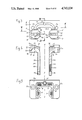
- FIG. 1 shows an overall perspective view of an anti-friction bearing according to the present invention
- FIG. 2a shows an end view in half section of a rail guide with installed retaining webs which forms part of the bearing of FIG. 1,
- FIG. 2b shows a side view of the said rail guide
- FIG. 2c shows an end view similar to FIG. 2a but illustrating another embodiment
- FIG. 2d shows a side view similar to FIG. 2b but illustrating the said other embodiment
- FIG. 2e is an enlarged sectional view showing load-transmitting ball rows of the bearing
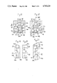
- FIG. 3 shows a view of end plates of the bearing, seen from the inside
- FIG. 4 shows a section on the line IV--IV of FIG. 3,
- FIG. 5 shows a view of the end plates, seen from outside
- FIG. 6 is an enlarged view of a retaining web shown at VI in FIG. 3,
- FIG. 7 is an enlarged view of a snap connection shown at VII in FIG. 4,
- FIG. 8 is a section taken on the line VIII--VIII of FIG. 3,
- FIG. 9 shows a deflection piece in an installed condition
- FIG. 9a is a section taken on the line IXa--IXa of FIG. 9,
- FIG. 10 shows a side view of a flat side of a semi-cylindrical deflection piece
- FIG. 10a is a section taken on the line Xa--Xa of FIG. 10,
- FIG. 11 is a plan view of the deflection piece shown in FIG. 10,
- FIG. 12 is an outside view of a sealing plate
- FIG. 13 is a section taken on the line XIII--XIII of FIG. 12,
- FIG. 14 shows a further embodiment of a bearing according to the present invention
- FIG. 15 is a view of a contact surface of an end plate forming part of an embodiment of the bearing of the present invention having intersecting roller circulation channels,
- FIG. 16 shows a section taken on the line XVI--XVI of FIG. 15,
- FIG. 17 shows a section taken on the line XVII--XVII of FIG. 15,
- FIG. 18 shows a section taken on the line XVIII--XVIII of FIG. 15,
- FIG. 19 is an exploded view of inner and outer deflection pieces forming part of the embodiment of FIGS. 15 to 18,
- FIG. 20 is an exploded view of the said inner and outer deflection pieces when turned round through 90°
- FIG. 21 is a perspective exploded view of the structure shown in FIGS. 19 and 20,
- FIG. 22 shows a modification of the structure of FIG. 15 in which securing members are provided for the rollers
- FIG. 23 is a view, corresponding to FIG. 15, of the contact surface of an end plate in another embodiment of a bearing according to the present invention.
- FIG. 24 shows a section taken on the line XXIV--XXIV of FIG. 23,
- FIG. 25 is a perspective view of a deflection piece forming part of the embodiment of FIG. 23,
- FIG. 26 is a view of the deflection piece according to FIG. 25 looking in the direction of arrow XXVI of FIG. 25,
- FIG. 27 is a view looking in the direction of arrow XXVII of FIG. 25,
- FIG. 28 is a view of a spacer between two successive rollers in the region of a curved rolling member row of a further embodiment of a bearing according to the present invention.
- FIG. 29 is a plan view of a spacer according to FIG. 28 between two successive rollers which are axially parallel to each other, i.e. located in the area of a load-transmitting rolling member row or a row of rolling members running in the reverse direction.
- FIGS. 1, 2a and 2b there is shown an anti-friction bearing according to the present invention.
- a bearing main body 1 is mounted on and adapted to be moved axially along a rail 2.
- the bearing main body 1 has four ball circulation channels or circuits A, B, C and D (FIG. 2a) and is thus provided with axially running, load-carrying ball rows A1, B1 . . . , which are associated with four load-absorbing tracks A12, B12, C12 and D12 (FIG. 1) incorporated in the rail 2.
- This enables parts which can be displaced relative to one another to be moved longitudinally even when the bearing main body 1 or the rail 2 is acted upon simultaneously by a torque.
- Ball rows A2 and B2 (FIG.
- the bearing main body 1 is fixed together by bolted connections having through bores 15 which, with respect to the plane S--S of symmetry, are located in the outer area of the bearing main body 1 and in its plane S--S of symmetry, namely at 15a.
- threaded bores 16 and 16a can also be provided instead of the through bores 15a.
- FIGS. 3 and 4 show an inside view and a section of a half of a plastics cage divided in two in a plane normal to the axis.
- Each said half consists of an end plate 18 having a contact surface 19 (FIG. 1) and two axially extending retaining webs 20a and 20b which are made integrally with the end plate 18.
- the webs 20a, 20b are provided to guide the load-transmitting ball rows A1, B1 . . . in the bearing main body 1 during the motion cycle. That is to say, the purpose of the webs 20a, 20b is to hold the said ball rows by means of retaining grooves A14, B14 . . .
- FIG. 2e where the peripheral areas of the load-transmitting ball rows A1, B1 . . . , which peripheral areas engage the tracks and retaining grooves A11, B11 . . . ; A12, B12, . . . ; A14, B14 . . . , are designated as ⁇ , ⁇ and ⁇ respectively.
- the sum ⁇ + ⁇ of the angles is greater than 180°.
- Corresponding semi-cylindrical deflection pieces 36 are placed in the deflection-piece locating channels 25 during assembly.
- a lubricant supply channel 26 (FIG. 3) having a semi-cylindrical cross-section extends in continuation of the deflection-piece locating channels 25 up to the axis S--S of symmetry of the end plate 18, where a lubricating bore or connection 27 having a threaded connection ensures that the four ball circulation channels A, B, C and D are supplied with lubricant.
- the plastics cage halves 18, 20a and 20b are fixed on the bearing main body 1 of the bearing element via two bores 27a in the end plate 18 of the cage.
- a recess 28 (FIG. 5) enables a sealing plate 29 (FIGS. 2a and 2c) to be incorporated.
- the sealing plate 29 is anchored via a plurality of snap connections 30 and 39 (FIGS. 4, 7, 12, 13).
- the sealing plate 29 which is incorporated in the plastics cage, by virtue of its sealing edge 29a (FIG. 12) which follows the profile of the rail 2, at least prevents the penetration of dirt. Additionally inserted sealing strips 40 and 41 (FIG. 2a), which are attached to the bearing main body 1 directly above (40) or below (41) the load-transmitting ball rows A1 and B1 and to the end plates 18, and which reach as far as the sealing plates 29, ensure that no dirt which may have reached the bearing main body 1 via the central bores 17 reaches the balls or the contact zone with the rail 2. Thus a substantially hermetic sealing of the rolling-contact area is made possible.
- the recess 28 for receiving the sealing plate 29 is clearly shown in FIG. 5, and the position of the snap elements 30 and 39 is clearly shown in FIGS. 5, 7, 12 and 13.
- FIG. 6 shows a retaining web 20b, as illustrated in FIG. 3, on a larger scale.
- two retaining grooves A14 and B14 are integrally formed on the retaining web 20b.
- the retaining web 20b is secured over its entire length against bending by a spring 32b which extends into a corresponding groove 32a (FIG. 2e) in the bearing main body 1.
- the retaining webs 20a and 20b of the two cage halves are connected to one another by pins 33a inserted into a bore 33b.
- FIG. 7 shows the construction of a C-shaped section 30 of the snap connection 39 with which the sealing plate 29 is fixed to the end plate 18.
- Two resilient tongues 34 curved in an arch shape, together with a cavity 35, form a C-section.
- a correspondingly formed bulbous section 39 (FIG. 13) on the sealing plate 29 is adapted to be snapped into the C-section by the resilient tongues 34 being deflected aside.
- the section VIII--VIII indicated in FIG. 3 is shown in FIG. 8.
- the symmetrical lubricant supply channel 26 (see FIG. 3), which is U-shaped, has a semi-cylindrical cross-section.
- the semi-cylindrical deflection piece 36 shown in FIGS. 9, 9a, 10, 10a and 11, on its flat rear side 36b, has a longitudinal distribution channel 26a as a continuation of the lubricant supply channel 26 which has the same cross-section.
- Two transverse bores 37 in the deflection piece 36 connect the longitudinal distribution channel 26a to the curved ball rows A3, B3 . . .
- the transverse bores 37 communicate with the inner deflection surfaces 36a which are integrally formed on the deflection pieces 36.
- the inner deflection surfaces 36a is provided for the inner guidance of the curved ball rows A3, B3 . . . and ensures a smooth ball movement.
- FIGS. 12 and 13 show the outer and inner contours of the sealing plate 29 and in the shape of its sealing lip 29a.
- the sealing plate 29 is fixed via the snap connections which fix the sealing plate 29 to the plastics cage halves 18, 20a and 20b.
- the sealing plate 29 is made of relatively soft plastics or rubber material.
- FIG. 14 shows one way of using a bearing according to the present invention.
- the bearing main body 1 For special installation cases, it can be advantageous to divide the bearing main body 1 to enable, for example, a wider rail 2 to be assembled.
- the bearing main body 1 and the cage 2 As a result of the position of the ball circulation channels and the cage design resulting therefrom having only one group of aligned retaining webs 20a and 20b for two load-transmitting ball rows, it is possible to divide the bearing main body 1 and the cage 2 at relatively low expense along the plane S--S of symmetry.
- the seal is maintained. Only the lubricant supply has to be modified, so that the two parts 40a and 40b of the bearing main body 1, which parts arise from the division of the latter, can be lubricated individually.
- the rail 2 is also divided, namely into two profiled parts 42a and 42b and possibly an intermediate piece 42c, the range of the bearing application is increased still further. In principle, longitudinal guides of any width can therefore be achieved, the intermediate piece 42c being
- the lubricant connection 27 is mounted in the end plate 18 on the front surface 19a thereof. If means are added for raising the lubricant pressure so as to force lubricant into the lubricant supply channel 26, then the force with which the lubricant is pressed against the end plate 18 balances the force which is built up by the pressure of the lubricant in the lubricant supply channel 26. In this way, the end plate 18, which consists of plastics material, is prevented from lifting away from the adjacent end surface 1d of the bearing main body 1. In this way also, the lubricant is prevented from escaping between the end face 1d and the front surface 19 of the end plate 18 and thereby prematurely giving the impression that all parts of the bearing to be lubricated have already been sufficiently lubricated.
- FIGS. 15 to 22 show an embodiment of the present invention in which the balls are replaced by rollers. Analogous parts have the same reference numerals as in FIGS. 1 to 14 but increased by 100.
- FIG. 15 shows an end plate 118 whose contact surface 119 faces the bearing main body (not shown).
- the end plate 118 contains a lubricant supply channel 126.
- Two pairs of roller bearings are shown on each side of the rail (not marked), it being sufficient to describe the left hand half of FIG. 15, in which it is possible to see roller circulation channels or circuits A, B.
- the roller circulation circuits A,B are arranged in intersecting planes 145, 146.
- the planes 145, 146 intersect along a line of intersection E, which is parallel to the longitudinal axis of the rail (not marked) and the bearing main body.
- the load-transmitting roller rows are indicated as A1 and B1, the roller rows running in the reverse direction being indicated as B2 and A2.
- the load-transmitting roller rows A1, B1 are adapted to rest against load-absorbing tracks B12, A12 of the rail.
- the roller rows A2, B2 running in the reverse direction are guided in return channels A21, B21 of square cross section.
- the apices of the curved roller rows B3, A3 are staggered in the axial direction of the rail and intersect each other.
- the curved roller row B3 further from the bearing main body is designated the outer curved roller row, and the curved roller row A3 nearer the bearing main body is designated the inner curved roller row.
- the outer curved roller row B3 comprises an outer deflection surface 147 which is formed by an indentation or countersunk portion 148 in the end plate 118.
- the curved roller row B3 also comprises an inner deflection surface 149 which is formed partially, i.e. at 149a from an outer deflection piece 150 and partially, i.e. at 149b, from an inner deflection piece 151.
- the inner curved roller row A3 comprises an outer deflection surface 152 which is formed partially, i.e. at 152a, from the outer deflection piece 150 and partially, i.e. at 152b, from the indentation 148.
- the inner curved roller row A3 also comprises an inner deflection surface 163, which is formed from the inner deflection piece 151.
- the deflection pieces 150, 151 are arranged to abut each other in the countersunk portion 148.
- the arrangement is such that the section 149a of the inner deflection surface 149 of the outer curved roller row B3 is connected to sections 149b of the deflection surface 149 of the outer curved roller row B3.
- the arrangement is also such that the section 152a of the outer deflection surface 152 of the inner curved roller row is connected to sections 152b of the outer deflection surface 152 of the inner curved roller row A3.
- the inner deflection piece 151 comprises a rear face 151b (FIG. 18) which is positioned flush with the contact surface 119 of the end plate 118.
- a longitudinal distributing channel 126a is formed in the rear face 151b of the inner deflection piece 151, the distribution channel 126a being joined to the lubricant supply channel 126 and connected via a transverse bore 137 to the inner curved roller row A3.
- Retaining webs 120b and 120a are formed on the end plate 118 and hold the load-transmitting roller rows A1 and B1 in engagement with the tracks (not shown) of the bearing main body.
- the end plates 118 at the two ends of the bearing main body are identical to each other, such that only one mould is used to produce the end plates.
- the curved roller row A3, belonging to the roller circulation channel or circuit A, of the opposite end plate is an outer curved roller row and that the curved roller row B3, belonging to the opposite end plate, of the roller circuit circulation channel or B is an inner curved roller row.
- the roller circulation channels or circuits A and B are the same length and the end plates are the same shape. In this way also it is ensured that each roller circulating channel or circuit A, B can be lubricated as shown in FIGS. 17 and 18.
- FIG. 22 it is further indicated how the load-carrying roller rows A1, B1 can be secured against falling out of the bearing by projections 154 on the end plate or bearing main body.
- Corresponding projections can also be attached to the retaining webs 120a, 120b. Since the retaining webs 120a, 120b can consist of relatively soft resilient material, as can the end plates 118 also, it is possible without further modifications to press the rollers past the projections 154 into their working position inside the load-carrying roller rows A1, B1.
- the rollers are preferably fixed in the plane separating the two retaining webs 120a, the two cage halves 118 being separated from each other during assembly by the diameter of the rollers. The possibility of this kind of assembly also exists for the other embodiments, even those with balls.
- the construction of the linear bearing with rollers has the advantage that even greater loads can be carried.
- the rollers can be constructed as cylindrical rollers, as shown in FIGS. 15 to 21. However, they can also be constructed as barrels, i.e. as cambered rollers, or even with a substantially smaller diameter, in which case they are called needles.
- FIGS. 15 to 21 has the advantage that the two roller circulation channels or circuits A, B, as seen in FIG. 15, can be accommodated in relatively little space.
- the disadvantage has to be accepted that the two roller circulation channels or circuits need to be staggered in the longitudinal direction of the rail.
- this disadvantage entails only a relatively slight extension of the bearing. The load-carrying capacity of the bearing in relation to torque is also maintained practically without change.
- FIGS. 23 to 27 show a further embodiment with rollers. Analogous parts are given the same reference numerals as in the embodiment of FIGS. 1 to 14, but each increased by 200.
- roller circulation channels or circuits A, B are arranged with the load-carrying roller rows A1, B1 respectively and the roller rows A2, B2 respectively, which run in the reverse direction, being disposed in parallel planes F, G.
- the planes F, G could also be inclined at an acute angle to each other, so that they intersect at a position beyond the roller circulation channels or circuits A, B.
- the load-carrying roller rows A1, B1 roll over the tracks A12, B12 respectively of the rail, which is otherwise not shown.
- the roller rows A2 and B2 running in the reverse direction are guided in return channels A21 and B21 of the bearing main body, which channels are not shown per se in FIG. 23 and extend upwards at right angles to the plane of the drawing.
- a countersunk portion 248 (FIG. 24) is formed in the end plate 218 and forms an outer deflection surface 255.
- the outer deflection surface 255 is assembled from two outer partial deflection surfaces 255a and 255b. Both partial deflection surfaces 255a and 255b are conical around an axis H.
- the rollers of curved roller row A3 roll with their circumferential surfaces against the partial deflection surface 255a.
- One of the end faces of the rollers of the curved roller row A3 slides against the partial deflection surface 255b.
- a deflection piece 256 comprising an inner deflection surface 257 (FIG. 25).
- the inner deflection surface 257 is assembled from two partial deflection surfaces 257a and 257b.
- the partial deflection surface 257a aids the rolling of the circumferential surfaces of the rollers of curved roller row A3, while the other end faces of the rollers adjoin the partial deflection surface 257b.
- the partial deflection surfaces 257a and 257b are also conical surfaces around the axis H.
- a rear surface 258 of the deflection piece 256 lies flush with the contact surface 219 of the end plate 218.
- this rear surface 258 there is formed a longitudinal distribution channel 226a which is connected to the lubricant supply channel in the end plate 218.
- a transverse bore 237 leads from the longitudinal distribution channel 226a to the inner deflection surface 257.
- the inner deflection surfaces for the curved roller rows A3 and B3 of the two roller circulation channels or circuits A, B are formed on the deflection piece 256.
- FIGS. 23 to 27 has, as does the embodiment of FIGS. 15 to 21, the advantage that the two circulation channels or circuits A, B, as seen in FIGS. 23, can be accommodated in a small space. It is not necessary for the curved roller rows to intersect.
- the longitudinal extension of the two circulation channels or circuits A, B inside the bearing main body and the end plates is identical.
- the problems resulting from the arrangement of the curved roller rows A3, B3 with roller axes inclined towards each other can be simply solved by the design of the deflection surfaces, especially if the end plates and the deflection surfaces consist of plastics material favourable to sliding.
- spacers 270 can be provided between successive rollers, which spacers, when viewed in a plane determined by the axes of two successive rollers (FIG. 28) are double-trapezoidal in form and, as the enlarged plan view of FIG. 29 shows, have grooves 271 in their circumferential surfaces to receive successive rollers. The movement of the rollers in the curved roller rows is substantially improved by these spacers.
- the load-carrying roller rows A1, B1 can be secured in the same way as in FIG. 22 by the projections 154.
- the retaining webs 220a and 220b can also be formed on the end plates 218.
- the two end plates 218 can be identical in shape.
- the retaining webs can also be separate from the end plates, so that four parts may be needed for the construction of each cage, i.e. two end plates and two retaining webs, the retaining webs engaging with both ends in the end plates and being held there preferably unrotatably.
Landscapes
- Engineering & Computer Science (AREA)
- General Engineering & Computer Science (AREA)
- Mechanical Engineering (AREA)
- Bearings For Parts Moving Linearly (AREA)
- Rolling Contact Bearings (AREA)
Applications Claiming Priority (4)
| Application Number | Priority Date | Filing Date | Title |
|---|---|---|---|
| DE3527886 | 1985-08-02 | ||
| DE19853527886 DE3527886A1 (de) | 1985-08-02 | 1985-08-02 | Waelzlager fuer linearbewegungen |
| DE3620571 | 1986-06-19 | ||
| DE19863620571 DE3620571C2 (de) | 1986-06-19 | 1986-06-19 | Linearrollenlager |
Publications (1)
| Publication Number | Publication Date |
|---|---|
| US4743124A true US4743124A (en) | 1988-05-10 |
Family
ID=25834706
Family Applications (1)
| Application Number | Title | Priority Date | Filing Date |
|---|---|---|---|
| US06/893,195 Expired - Lifetime US4743124A (en) | 1985-08-02 | 1986-08-04 | Anti-friction bearing |
Country Status (5)
| Country | Link |
|---|---|
| US (1) | US4743124A (fr) |
| EP (1) | EP0211243B1 (fr) |
| DD (2) | DD302032A7 (fr) |
| DE (1) | DE3668672D1 (fr) |
| ES (1) | ES2000826A6 (fr) |
Cited By (26)
| Publication number | Priority date | Publication date | Assignee | Title |
|---|---|---|---|---|
| US4799804A (en) * | 1987-12-28 | 1989-01-24 | Nippon Thompson Co., Ltd. | Four track-type endless rectilinear motion guide unit |
| US4799805A (en) * | 1987-12-28 | 1989-01-24 | Nippon Thompson Co. Ltd. | Four track-type endless rectilinear motion guide unit |
| US4869600A (en) * | 1987-11-30 | 1989-09-26 | Tsubakimoto Precision Products Co., Ltd. | Linear motion ball bearing |
| US4932067A (en) * | 1989-05-30 | 1990-06-05 | Thomson Industries, Inc. | Linear motion bearing |
| US5033870A (en) * | 1989-09-20 | 1991-07-23 | Deutsche Star Gmbh | Linear guide |
| US5176454A (en) * | 1990-10-16 | 1993-01-05 | Deutsche Star Gmbh | Elastic bearing block for a linear guide |
| WO1993020363A1 (fr) * | 1992-03-28 | 1993-10-14 | Ina Wälzlager Schaeffler Kg | Roulement pour mouvement rectiligne |
| US5295748A (en) * | 1992-10-15 | 1994-03-22 | Nippon Bearing Co., Ltd. | Ball bearing for rectilinear sliding |
| DE4301435A1 (de) * | 1993-01-20 | 1994-07-21 | Star Gmbh | Verfahren zur Anbringung einer Linearführungsschiene auf einer Basiseinheit |
| US5509736A (en) * | 1993-09-10 | 1996-04-23 | Deutsche Star Gmbh | Linear guiding device |
| US5584581A (en) * | 1993-09-10 | 1996-12-17 | Deutsche Star Gmbh | Linear guiding device |
| EP1013950A2 (fr) | 1998-12-23 | 2000-06-28 | Rexroth Star GmbH | Unité de guidage |
| US6203199B1 (en) | 1998-07-06 | 2001-03-20 | Deutsche Star Gmbh | Linear guide device |
| US6443619B1 (en) | 1998-12-23 | 2002-09-03 | Rexroth Star Gmbh | Guide unit |
| US6461046B2 (en) * | 2000-04-04 | 2002-10-08 | Helmut Kahl | System for adjusting play in a linear guide |
| EP1342929A1 (fr) * | 2002-02-28 | 2003-09-10 | NSK Ltd. | Guide linéaire |
| US6619845B2 (en) * | 2000-03-21 | 2003-09-16 | Thk Co., Ltd. | Roller retainer, direct-acting guide device and roller screw using the roller retainer |
| US20060201782A1 (en) * | 2005-03-10 | 2006-09-14 | Thk Co., Ltd, | Guide apparatus |
| US20080037914A1 (en) * | 2004-09-06 | 2008-02-14 | Thk Co., Ltd. | Motion Guide Device |
| DE102007056862A1 (de) * | 2007-11-26 | 2009-05-28 | Robert Bosch Gmbh | Linearrollenlager mit Umlenkstück |
| DE202009014395U1 (de) | 2009-10-24 | 2011-03-10 | Robert Bosch Gmbh | Linearführungsvorrichtung mit geschützter Dichtlippe |
| US20130315515A1 (en) * | 2012-05-23 | 2013-11-28 | Chieftek Precision Co., Ltd. | Circulation maintaining device for linear slide assembly |
| US20140376838A1 (en) * | 2013-06-19 | 2014-12-25 | Chieftek Precision Co., Ltd. | Slider assembly |
| US10364841B2 (en) * | 2015-09-18 | 2019-07-30 | Nsk Ltd. | Linear motion guide device and end cap for linear motion guide device |
| CN110173508A (zh) * | 2019-06-11 | 2019-08-27 | 海盐博友五金制造有限责任公司 | 一种承载效果好的耐磨损直线导轨 |
| US11305406B2 (en) * | 2019-02-19 | 2022-04-19 | Makita Corporation | Power tool having hammer mechanism |
Families Citing this family (11)
| Publication number | Priority date | Publication date | Assignee | Title |
|---|---|---|---|---|
| US4832508A (en) * | 1986-09-09 | 1989-05-23 | Hiroshi Teramachi | Rectilinear slide ball bearing |
| GB2203804B (en) * | 1987-03-20 | 1991-10-16 | Hiroshi Teramachi | Angular contact-linear slide bearing |
| DE3910457A1 (de) * | 1989-03-31 | 1990-10-04 | Star Gmbh | Linearkugelbuechse |
| US4927272A (en) * | 1989-05-22 | 1990-05-22 | The Warner & Swasey Company | Linear bearing with improved lubrication system and method |
| US5672011A (en) * | 1991-09-06 | 1997-09-30 | Ina Walzlager Schaeffler Kg | Rolling bearing for linear movements |
| DE4209824A1 (de) * | 1991-09-06 | 1993-03-11 | Schaeffler Waelzlager Kg | Waelzlager fuer linearbewegungen |
| DE4141038A1 (de) * | 1991-12-12 | 1993-06-17 | Schaeffler Waelzlager Kg | Abstreifereinheit fuer ein lagerelement |
| DE4415704B4 (de) * | 1994-05-04 | 2005-01-27 | Ina-Schaeffler Kg | Linearwälzlager |
| DE19613626A1 (de) * | 1996-04-04 | 1997-10-09 | Star Gmbh | Linearführungseinrichtung |
| DE19647173C2 (de) * | 1996-11-14 | 2001-06-13 | Rexroth Star Gmbh | Schraubverankerung für einen Schmierstoffanschlußteil an einem Linearführungswagen |
| CN111720715A (zh) * | 2020-06-19 | 2020-09-29 | 杭州职业技术学院 | 一种计算机主板加工用负压除尘装置 |
Citations (17)
| Publication number | Priority date | Publication date | Assignee | Title |
|---|---|---|---|---|
| DE1425966A1 (de) * | 1964-07-22 | 1969-04-10 | Ionow Walentin W | Waelzlager fuer geradlinige Bewegung |
| DE3005579A1 (de) * | 1979-02-14 | 1980-08-28 | Hiroshi Teramachi | Lineare kugellagereinheit |
| DE3148331A1 (de) * | 1981-02-23 | 1982-11-11 | Hiroshi Teramachi | Linearkugellager |
| DE3227902A1 (de) * | 1981-08-11 | 1983-03-10 | Hiroshi Teramachi | Linearkugellagereinheit |
| DE3238980A1 (de) * | 1981-11-18 | 1983-05-26 | Nippon Seiko Kk | Gleitbahnlager |
| DE3303831A1 (de) * | 1982-02-12 | 1983-08-25 | Hiroshi Teramachi | Kugelschiebelager- und schiebewellen-anordnung |
| FR2523669A1 (fr) * | 1982-03-16 | 1983-09-23 | Teramachi Hiroshi | Ensemble combine de palier lineaire a recirculation de billes et de rail de guidage |
| DE3304895A1 (de) * | 1982-02-13 | 1983-10-06 | Hiroshi Teramachi | Endloslinearkugellager |
| DE3313575A1 (de) * | 1982-04-14 | 1983-10-20 | Nippon Seiko Kk | Fuehrungsbahnlager |
| DE3224282A1 (de) * | 1982-06-28 | 1983-12-29 | Hiroshi Teramachi | Linearkugellagereinheit |
| DE3400849A1 (de) * | 1983-02-15 | 1984-08-16 | Nippon Thompson Co Ltd | Umlenkweg eines rollenlagers fuer eine endlose linearbewegung |
| EP0120093A1 (fr) * | 1982-09-24 | 1984-10-03 | Tsubakimoto Precision Products Co., Ltd. | Palier a billes a fonctionnement lineaire |
| DE3313129A1 (de) * | 1983-04-12 | 1984-10-18 | Neff Gewindespindeln | Linearlageranordnung zur geradlinigen fuehrung eines schlittens laengs einer fuehrungsschiene |
| DE3324840A1 (de) * | 1983-04-18 | 1984-10-25 | Schneeberger Ag Maschf | Waelzkoerperumlauflager |
| DE3333754A1 (de) * | 1983-09-19 | 1985-04-04 | Helmut 6232 Bad Soden Kremer | Pneumatischer basslautsprecher |
| EP0138360A2 (fr) * | 1983-10-14 | 1985-04-24 | Ichiro Katayama | Ensemble de palier pour dispositif coulissant |
| EP0197150A1 (fr) * | 1984-10-11 | 1986-10-15 | Tsubakimoto Precision Products Co., Ltd. | Roulement a billes pour parties en mouvement lineaire |
-
1986
- 1986-07-03 EP EP86109116A patent/EP0211243B1/fr not_active Expired - Lifetime
- 1986-07-03 DE DE8686109116T patent/DE3668672D1/de not_active Expired - Lifetime
- 1986-07-31 DD DD34442786A patent/DD302032A7/de active IP Right Grant
- 1986-07-31 DD DD29332186A patent/DD248850B5/de active IP Right Maintenance
- 1986-08-01 ES ES8600826A patent/ES2000826A6/es not_active Expired
- 1986-08-04 US US06/893,195 patent/US4743124A/en not_active Expired - Lifetime
Patent Citations (18)
| Publication number | Priority date | Publication date | Assignee | Title |
|---|---|---|---|---|
| DE1425966A1 (de) * | 1964-07-22 | 1969-04-10 | Ionow Walentin W | Waelzlager fuer geradlinige Bewegung |
| DE3005579A1 (de) * | 1979-02-14 | 1980-08-28 | Hiroshi Teramachi | Lineare kugellagereinheit |
| DE3148331A1 (de) * | 1981-02-23 | 1982-11-11 | Hiroshi Teramachi | Linearkugellager |
| DE3227902A1 (de) * | 1981-08-11 | 1983-03-10 | Hiroshi Teramachi | Linearkugellagereinheit |
| US4502737A (en) * | 1981-11-18 | 1985-03-05 | Nippon Seiko Kabushiki Kaisha | Slide way bearing |
| DE3238980A1 (de) * | 1981-11-18 | 1983-05-26 | Nippon Seiko Kk | Gleitbahnlager |
| DE3303831A1 (de) * | 1982-02-12 | 1983-08-25 | Hiroshi Teramachi | Kugelschiebelager- und schiebewellen-anordnung |
| DE3304895A1 (de) * | 1982-02-13 | 1983-10-06 | Hiroshi Teramachi | Endloslinearkugellager |
| FR2523669A1 (fr) * | 1982-03-16 | 1983-09-23 | Teramachi Hiroshi | Ensemble combine de palier lineaire a recirculation de billes et de rail de guidage |
| DE3313575A1 (de) * | 1982-04-14 | 1983-10-20 | Nippon Seiko Kk | Fuehrungsbahnlager |
| DE3224282A1 (de) * | 1982-06-28 | 1983-12-29 | Hiroshi Teramachi | Linearkugellagereinheit |
| EP0120093A1 (fr) * | 1982-09-24 | 1984-10-03 | Tsubakimoto Precision Products Co., Ltd. | Palier a billes a fonctionnement lineaire |
| DE3400849A1 (de) * | 1983-02-15 | 1984-08-16 | Nippon Thompson Co Ltd | Umlenkweg eines rollenlagers fuer eine endlose linearbewegung |
| DE3313129A1 (de) * | 1983-04-12 | 1984-10-18 | Neff Gewindespindeln | Linearlageranordnung zur geradlinigen fuehrung eines schlittens laengs einer fuehrungsschiene |
| DE3324840A1 (de) * | 1983-04-18 | 1984-10-25 | Schneeberger Ag Maschf | Waelzkoerperumlauflager |
| DE3333754A1 (de) * | 1983-09-19 | 1985-04-04 | Helmut 6232 Bad Soden Kremer | Pneumatischer basslautsprecher |
| EP0138360A2 (fr) * | 1983-10-14 | 1985-04-24 | Ichiro Katayama | Ensemble de palier pour dispositif coulissant |
| EP0197150A1 (fr) * | 1984-10-11 | 1986-10-15 | Tsubakimoto Precision Products Co., Ltd. | Roulement a billes pour parties en mouvement lineaire |
Non-Patent Citations (4)
| Title |
|---|
| Catalog NR. 41 2G, THK Bearings of THK Co., Ltd. (no date). * |
| Catalog NR. 41-2G, "THK Bearings" of THK Co., Ltd. (no date). |
| Patent Abstracts of Japan, Ser. M 434, Nov. 30, 1985, No. 303 Roller Type Bearing for Linear Motion. * |
| Patent Abstracts of Japan, Ser. M-434, Nov. 30, 1985, No. 303--Roller Type Bearing for Linear Motion. |
Cited By (37)
| Publication number | Priority date | Publication date | Assignee | Title |
|---|---|---|---|---|
| US4869600A (en) * | 1987-11-30 | 1989-09-26 | Tsubakimoto Precision Products Co., Ltd. | Linear motion ball bearing |
| US4799805A (en) * | 1987-12-28 | 1989-01-24 | Nippon Thompson Co. Ltd. | Four track-type endless rectilinear motion guide unit |
| US4799804A (en) * | 1987-12-28 | 1989-01-24 | Nippon Thompson Co., Ltd. | Four track-type endless rectilinear motion guide unit |
| US4932067A (en) * | 1989-05-30 | 1990-06-05 | Thomson Industries, Inc. | Linear motion bearing |
| US5033870A (en) * | 1989-09-20 | 1991-07-23 | Deutsche Star Gmbh | Linear guide |
| US5176454A (en) * | 1990-10-16 | 1993-01-05 | Deutsche Star Gmbh | Elastic bearing block for a linear guide |
| US5445455A (en) * | 1992-03-28 | 1995-08-29 | Ina Walzlager Schaeffler Kg | Rolling bearing for linear movement |
| WO1993020363A1 (fr) * | 1992-03-28 | 1993-10-14 | Ina Wälzlager Schaeffler Kg | Roulement pour mouvement rectiligne |
| US5295748A (en) * | 1992-10-15 | 1994-03-22 | Nippon Bearing Co., Ltd. | Ball bearing for rectilinear sliding |
| DE4301435A1 (de) * | 1993-01-20 | 1994-07-21 | Star Gmbh | Verfahren zur Anbringung einer Linearführungsschiene auf einer Basiseinheit |
| US5509736A (en) * | 1993-09-10 | 1996-04-23 | Deutsche Star Gmbh | Linear guiding device |
| US5584581A (en) * | 1993-09-10 | 1996-12-17 | Deutsche Star Gmbh | Linear guiding device |
| DE4330772B4 (de) * | 1993-09-10 | 2013-02-14 | Robert Bosch Gmbh | Linearführungseinrichtung |
| US6203199B1 (en) | 1998-07-06 | 2001-03-20 | Deutsche Star Gmbh | Linear guide device |
| EP1013950A2 (fr) | 1998-12-23 | 2000-06-28 | Rexroth Star GmbH | Unité de guidage |
| US6443619B1 (en) | 1998-12-23 | 2002-09-03 | Rexroth Star Gmbh | Guide unit |
| US6619845B2 (en) * | 2000-03-21 | 2003-09-16 | Thk Co., Ltd. | Roller retainer, direct-acting guide device and roller screw using the roller retainer |
| US6779923B2 (en) | 2000-03-21 | 2004-08-24 | Thk Co., Ltd. | Roller retainer, direct-acting guide device and roller screw using the roller retainer |
| US6461046B2 (en) * | 2000-04-04 | 2002-10-08 | Helmut Kahl | System for adjusting play in a linear guide |
| US20040020067A1 (en) * | 2002-02-28 | 2004-02-05 | Nsk Ltd. | Linear guide apparatus |
| US6807746B2 (en) | 2002-02-28 | 2004-10-26 | Nsk Ltd. | Linear guide apparatus |
| EP1342929A1 (fr) * | 2002-02-28 | 2003-09-10 | NSK Ltd. | Guide linéaire |
| US8251588B2 (en) * | 2004-09-06 | 2012-08-28 | Thk Co., Ltd. | Motion guide device having direction changing passages that cross each other three-dimensionally and a method of assembling the same |
| US20080037914A1 (en) * | 2004-09-06 | 2008-02-14 | Thk Co., Ltd. | Motion Guide Device |
| US20060201782A1 (en) * | 2005-03-10 | 2006-09-14 | Thk Co., Ltd, | Guide apparatus |
| US7290647B2 (en) * | 2005-03-10 | 2007-11-06 | Thk Co., Ltd. | Guide apparatus |
| DE102007056862A1 (de) * | 2007-11-26 | 2009-05-28 | Robert Bosch Gmbh | Linearrollenlager mit Umlenkstück |
| US8057099B2 (en) | 2007-11-26 | 2011-11-15 | Robert Bosch Gmbh | Linear roller bearing with deflection piece |
| DE102007056862B4 (de) | 2007-11-26 | 2023-01-26 | Robert Bosch Gmbh | Linearrollenlager mit Umlenkstück |
| DE202009014395U1 (de) | 2009-10-24 | 2011-03-10 | Robert Bosch Gmbh | Linearführungsvorrichtung mit geschützter Dichtlippe |
| US20130315515A1 (en) * | 2012-05-23 | 2013-11-28 | Chieftek Precision Co., Ltd. | Circulation maintaining device for linear slide assembly |
| US8858082B2 (en) * | 2012-05-23 | 2014-10-14 | Chieftek Precision Co., Ltd. | Circulation maintaining device for linear slide assembly |
| US20140376838A1 (en) * | 2013-06-19 | 2014-12-25 | Chieftek Precision Co., Ltd. | Slider assembly |
| US8967862B2 (en) * | 2013-06-19 | 2015-03-03 | Chieftek Precision Co., Ltd. | Slider assembly |
| US10364841B2 (en) * | 2015-09-18 | 2019-07-30 | Nsk Ltd. | Linear motion guide device and end cap for linear motion guide device |
| US11305406B2 (en) * | 2019-02-19 | 2022-04-19 | Makita Corporation | Power tool having hammer mechanism |
| CN110173508A (zh) * | 2019-06-11 | 2019-08-27 | 海盐博友五金制造有限责任公司 | 一种承载效果好的耐磨损直线导轨 |
Also Published As
| Publication number | Publication date |
|---|---|
| DE3668672D1 (de) | 1990-03-08 |
| ES2000826A6 (es) | 1988-03-16 |
| EP0211243A3 (en) | 1987-05-20 |
| DD302032A7 (de) | 1996-06-27 |
| DD248850B5 (de) | 1994-07-21 |
| EP0211243B1 (fr) | 1990-01-31 |
| EP0211243A2 (fr) | 1987-02-25 |
Similar Documents
| Publication | Publication Date | Title |
|---|---|---|
| US4743124A (en) | Anti-friction bearing | |
| US4302059A (en) | Linear guide slide bearing unit | |
| JP4331820B2 (ja) | 直線運動装置用スペーサおよびそのスペーサを用いた直線運動装置 | |
| US5800064A (en) | Linear motion guide unit with elastic deformable sleeves | |
| US4595244A (en) | Recirculating-ball linear bearing | |
| US7066650B2 (en) | Linear motion guide unit | |
| KR19990044158A (ko) | 미끄럼운동 안내장치 및 그의 유단부 전동체 체인 | |
| US2681836A (en) | Block bearing | |
| US6276830B1 (en) | Linear guide assembly with positively guided cage | |
| GB2118638A (en) | Recirculating-ball linear bearing | |
| US20030231812A1 (en) | Linear rolling bearing | |
| JPH0366531B2 (fr) | ||
| CN115789086B (zh) | 一种带镶件的高刚性高负荷滚柱滑块 | |
| US3044835A (en) | Lineal anti-friction bearing | |
| KR102662273B1 (ko) | 슬라이딩 테이블 | |
| DE3905986C1 (en) | Live ring | |
| US6155719A (en) | Linear guide assembly with positively guided cage | |
| DE3620571A1 (de) | Waelzlager fuer linearbewegungen | |
| DE19941926A1 (de) | Linearwälzlager | |
| US7465094B2 (en) | Linear guide apparatus | |
| US3467447A (en) | Ball way package | |
| US3975064A (en) | Ball bushing | |
| EP0471340A2 (fr) | Palier linéaire | |
| US6709158B2 (en) | Linear motion guide unit with separator between any two adjoining rollers | |
| US4576422A (en) | Roller shoe structure |
Legal Events
| Date | Code | Title | Description |
|---|---|---|---|
| AS | Assignment |
Owner name: DEUTSCHE STAR GMBH, ERNST-SACHS-STRABE 90, D-8720 Free format text: ASSIGNMENT OF ASSIGNORS INTEREST.;ASSIGNOR:BLAUROCK, GUNTER;REEL/FRAME:004610/0214 Effective date: 19860728 Owner name: DEUTSCHE STAR GMBH, ERNST-SACHS-STRABE 90, D-8720 Free format text: ASSIGNMENT OF ASSIGNORS INTEREST;ASSIGNOR:BLAUROCK, GUNTER;REEL/FRAME:004610/0214 Effective date: 19860728 |
|
| STCF | Information on status: patent grant |
Free format text: PATENTED CASE |
|
| FEPP | Fee payment procedure |
Free format text: PAYOR NUMBER ASSIGNED (ORIGINAL EVENT CODE: ASPN); ENTITY STATUS OF PATENT OWNER: LARGE ENTITY |
|
| REMI | Maintenance fee reminder mailed | ||
| FPAY | Fee payment |
Year of fee payment: 4 |
|
| SULP | Surcharge for late payment | ||
| FPAY | Fee payment |
Year of fee payment: 8 |
|
| FEPP | Fee payment procedure |
Free format text: PAYER NUMBER DE-ASSIGNED (ORIGINAL EVENT CODE: RMPN); ENTITY STATUS OF PATENT OWNER: LARGE ENTITY |
|
| FPAY | Fee payment |
Year of fee payment: 12 |