US4757797A - Apparatus in ignition systems - Google Patents
Apparatus in ignition systems Download PDFInfo
- Publication number
- US4757797A US4757797A US07/030,157 US3015787A US4757797A US 4757797 A US4757797 A US 4757797A US 3015787 A US3015787 A US 3015787A US 4757797 A US4757797 A US 4757797A
- Authority
- US
- United States
- Prior art keywords
- voltage
- circuit
- transistor
- control circuit
- electronic switch
- Prior art date
- Legal status (The legal status is an assumption and is not a legal conclusion. Google has not performed a legal analysis and makes no representation as to the accuracy of the status listed.)
- Expired - Lifetime
Links
- 230000001939 inductive effect Effects 0.000 claims abstract description 4
- 238000004804 winding Methods 0.000 claims description 28
- 239000003990 capacitor Substances 0.000 claims description 21
- 239000004020 conductor Substances 0.000 description 2
- 230000015572 biosynthetic process Effects 0.000 description 1
- 238000010586 diagram Methods 0.000 description 1
- 230000004907 flux Effects 0.000 description 1
- 239000000696 magnetic material Substances 0.000 description 1
- 238000004519 manufacturing process Methods 0.000 description 1
- 230000035939 shock Effects 0.000 description 1
- 230000001052 transient effect Effects 0.000 description 1
Images

Classifications
-
- F—MECHANICAL ENGINEERING; LIGHTING; HEATING; WEAPONS; BLASTING
- F02—COMBUSTION ENGINES; HOT-GAS OR COMBUSTION-PRODUCT ENGINE PLANTS
- F02P—IGNITION, OTHER THAN COMPRESSION IGNITION, FOR INTERNAL-COMBUSTION ENGINES; TESTING OF IGNITION TIMING IN COMPRESSION-IGNITION ENGINES
- F02P1/00—Installations having electric ignition energy generated by magneto- or dynamo- electric generators without subsequent storage
- F02P1/08—Layout of circuits
- F02P1/086—Layout of circuits for generating sparks by discharging a capacitor into a coil circuit
-
- F—MECHANICAL ENGINEERING; LIGHTING; HEATING; WEAPONS; BLASTING
- F02—COMBUSTION ENGINES; HOT-GAS OR COMBUSTION-PRODUCT ENGINE PLANTS
- F02P—IGNITION, OTHER THAN COMPRESSION IGNITION, FOR INTERNAL-COMBUSTION ENGINES; TESTING OF IGNITION TIMING IN COMPRESSION-IGNITION ENGINES
- F02P3/00—Other installations
- F02P3/06—Other installations having capacitive energy storage
- F02P3/08—Layout of circuits
- F02P3/0807—Closing the discharge circuit of the storage capacitor with electronic switching means
- F02P3/0838—Closing the discharge circuit of the storage capacitor with electronic switching means with semiconductor devices
- F02P3/0846—Closing the discharge circuit of the storage capacitor with electronic switching means with semiconductor devices using digital techniques
Definitions
- flywheel magneto systems are being adapted for generating supply current to electronic apparatus connected thereto as well as conventional lighting current.
- Spark generating systems are in general use today, which work on the discharge of a capacitor by an ignition transformer, these being known as capacitive ignition systems.
- capacitive ignition systems Such systems are electrically very simple to handle and have great reliability.
- triggering capacitor ignition systems can easily be performed with the aid of pulses from a computer.
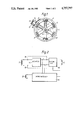
- FIG. 1 schematically illustrates a flywheel generator for use in connection with the embodiment in accordance with the invention.
- FIG. 2 is a basic circuit for an ignition system coacting with the flywheel magneto according to FIG. 1.
- FIG. 3 is a circuit diagram of the embodiment in accordance with the invention.
- the apparatus illustrated in FIG. 1 comprises a flywheel 1 mounted on a shaft 2 and including six magnets 3 uniformly distributed along the inside of the flywheel. The radially outmost faces of the magnets are magnetically connected to each other by an annular yoke 4 of magnetically conductive material. Centrally about the shaft there is a core 5 of magnetically conductive material from which there project six core legs 6. Each core leg is provided with a generator winding 7, the windings being electrically connected to form a voltage source. Different types of windings can of course be arranged on the core legs, e.g. a winding as the one 7 illustrated for use as a generator winding for electronic apparatus, and a further winding (not shown) intended for lighting.
- a magnetic tab 8 is mounted on the circumference of the flywheel 1 and has a length equivalent to an arc of about 30°. This tab is arranged to co-act magnetically with a magnetic circuit comprising two legs 9,10 of magnetic material, which are connected to each other by a permanent magnet 11. A winding 12 is mounted on one leg 10. This winding is intended to serve as a trigger winding, i.e. to provide a trigger voltage for the spark function.
- the flywheel is intended to rotate in the direction illustrated by the arrow 13.
- the windings 7 are here represented by a single winding connected to the input on a rectifier 14.
- the latter is the voltage source for a microprocessor 15 connected to the system, the trigger winding 12 being connected to the input of the processor, which has its output controlling triggering in a capacitive ignition circuit 16 connected to the system. Connections to a spark plug 17 depart from the capacitive ignition circuit.
- the generator windings 7 can be connected directly to the capacitive ignition circuit 16. When the flywheel 1 rotates, a voltage is generated in the windings 7 which accordingly energizes the microprocessor 15.
- the circuit according to FIG. 3 is assumed to be directly connected to the generator windings 7 via the lines 18,19.
- One end of the illustrated winding 7 is connected via the line 18 to a rectifier 20, which is in communication via a line 21 with a further similarly poled rectifier 22.
- a charge capacitor 24 is connected in series with the rectifier 22 by a line 23.
- the capacitor 24 is connected in series with the primary winding 27 of an ignition transformer 26 via line 25, the other end of the primary winding 27 being in turn connected to the line 19.
- the secondary winding 28 of the ignition transformer 26 is conventionally connected to the spark plug 17.
- a triac 29 is inserted between the lines 23 and 19, the control electrode 30 of the triac 29 being connected to the control output of the microprocessor 15.
- a voltage balancing resistor 31 is connected between lines 19 and 30.
- a Darlington transistor 32 is connected between the lines 21 and 19 via a low-ohmic resistor 33.
- a resistor 34 is connected between the resistor 33 and the Darlington transistor 32, the resistor 34 being connected in turn to the base of a transistor 36 via a line 35, the emitter-collector current path of the transistor 36 being connected between the lines 21 and 19 via a voltage divider comprising two resistors 37 and 38.
- a series circuit comprising a resistor 40 and a capacitor 41 is connected in parallel with a resistor 39 between the line 21 and the line 35.
- a further transistor 42 is coupled between the line 35 and the output 43 between the resistors 37 and 38.
- the base of the transistor 42 is connected to a point 44 in the connection between the resistor 37 and collector of the transistor 36. From this point 44 there is a connection via a varistor 45 to the line 23.
- An RC circuit comprising a resistor 46 and a capacitor 47 is connected to a line 48 which, via a diode 49, is connected to the output point 43 between the resistors 37 and 38.
- the line 48 is connected to the base of a further transistor 50, the emitter-collector path of which is coupled into a series circuit between the lines 21 and 19 via a further transistor 51 with a line 52 and a resistor 53 to the line 19.
- the line 52 is in direct communication with the base of the Darlington transistor 32.
- a voltage divider circuit comprising two resistors 54 and 55, the tap point 56 between these resistors being in communication with the base of the transistor 51.
- a further circuit is connected into the system, this circuit comprising a thyristor 57 coupled between the lines 24 and 19.
- the control electrode 58 of the thyristor is connected to the connection point between a capacitor 59 and a resistor 60 forming a series circuit between the lines 23 and 19.
- the illustrated circuit functions in the following manner. It is assumed that a positive voltage half-wave is being built up in the line 18.
- the Darlington transistor 32 is in a conductive state, resulting in that current begins to flow through the rectifier 20 and line 21 through the resistor 33, Darlington transistor 32 and once again through the line 19.
- the voltage tends to increase, but due to the conductive state of the Darlington transistor a current shock will be built up in the mentioned current path.
- a small voltage drop now occurs across the low-ohmic resistor 33, this voltage drop increasing with the current increase and finally forming a sufficient control voltage for the base in the transistor 36.
- This transistor will then be conductive, whereon current flows through the voltage divider 37,38 and consequently applies control voltage to the base of the transistor 42.
- the voltage at the point 43 thus increases, signifying that the current path which was previously present through the resistor 46, diode 49 and resistor 38 ceases, current to the base of the transistor 50 also ceasing, thus taking the transistor 50 out of its conductive state.
- the base current to the transistor 32 thus ceases and the transistor comes into its non-conductive state. This sudden condition results in a considerable voltage increase between the lines 21 and 19, signifying that current will now flow through the rectifier 22 via the line 23 to supply the capacitor 24.
- the thyristor 57 is arranged to avoid this, the RC link comprising capacitor 59 and resistor 40 forming a control circuit for controlling the thyristor 57 so that if there is an overvoltage, the thyristor 57 is caused to come into its conductive state, thus shunting the primary winding 27 and forming a bypass line for it.
- connection including the varistor 45 between the line 23 and take-off point 44. If voltages should become too high, pulses will be applied to the take-off point 44, signifying a voltage increase across the voltage divider 37,38 such that base current to the transistor 42 is generated, which in turn results in that the self-holding of the transistors 36 and 42 is achieved, resulting in that the Darlington transistor 32 will remain non-conductive.
- the previously mentioned RC networks 40,41 and 46,47, respectively, are connected to the associated transistor system circuits.
- an apparatus in accordance with the invention an extremely efficient circuit, which may provide the necessary voltages for charging the capacitor in the associated capacitive ignition system. Since the same voltage source can be used for both microprocessor and ignition means, a great deal is won from the point of view of manufacture, since the generator winding side can be formed very simply and robustly, which is particularly necessary with regard to use in motorcycles. It may be mentioned that in practice the generator includes more poles than the six illustrated, e.g. twelve, thus obtaining more flux changes and consequently pulses for each revolution.
Landscapes
- Engineering & Computer Science (AREA)
- Chemical & Material Sciences (AREA)
- Combustion & Propulsion (AREA)
- Mechanical Engineering (AREA)
- General Engineering & Computer Science (AREA)
- Ignition Installations For Internal Combustion Engines (AREA)
Applications Claiming Priority (2)
| Application Number | Priority Date | Filing Date | Title |
|---|---|---|---|
| SE8601442 | 1986-03-27 | ||
| SE8601442A SE454529B (sv) | 1986-03-27 | 1986-03-27 | Anordning for alstrande av laddspenning vid kondensatortendsystem |
Publications (1)
| Publication Number | Publication Date |
|---|---|
| US4757797A true US4757797A (en) | 1988-07-19 |
Family
ID=20363997
Family Applications (1)
| Application Number | Title | Priority Date | Filing Date |
|---|---|---|---|
| US07/030,157 Expired - Lifetime US4757797A (en) | 1986-03-27 | 1987-03-24 | Apparatus in ignition systems |
Country Status (3)
| Country | Link |
|---|---|
| US (1) | US4757797A (de) |
| EP (1) | EP0243330A3 (de) |
| SE (1) | SE454529B (de) |
Cited By (5)
| Publication number | Priority date | Publication date | Assignee | Title |
|---|---|---|---|---|
| US5283516A (en) * | 1993-02-24 | 1994-02-01 | Pass & Seymour Legrand | Low voltage dimmer with no load protection |
| US5392753A (en) * | 1993-11-22 | 1995-02-28 | R. E. Phelon Company, Inc. | Microprocessor controlled capacitor discharge ignition system |
| US5443055A (en) * | 1991-12-07 | 1995-08-22 | Robert Bosch Gmbh | Ignition system for internal combustion engines |
| US20030178005A1 (en) * | 2002-03-12 | 2003-09-25 | Fewell Roy J. | Processor controlled discharge ignition with fixed firing angle at startup |
| US20090272354A1 (en) * | 2006-08-11 | 2009-11-05 | Kokusan Denki Co., Ltd. | Capacitor discharge ignition device for engine |
Families Citing this family (1)
| Publication number | Priority date | Publication date | Assignee | Title |
|---|---|---|---|---|
| SE529860C2 (sv) | 2006-04-03 | 2007-12-11 | Sem Ab | Metod och anordning för att höja gnistenergin i kapacitiva tändsystem |
Citations (7)
| Publication number | Priority date | Publication date | Assignee | Title |
|---|---|---|---|---|
| US4404940A (en) * | 1980-04-30 | 1983-09-20 | Allied Corporation | Engine speed limiting circuit |
| US4436076A (en) * | 1981-09-25 | 1984-03-13 | R. E. Phelon Company, Inc. | Electronic speed control for capacitor discharge ignition system |
| US4462363A (en) * | 1980-10-14 | 1984-07-31 | Kokusan Denki Co., Ltd. | Ignition system for internal combustion engine |
| US4611569A (en) * | 1984-06-11 | 1986-09-16 | Kioritz Corporation | Ignition system |
| US4612899A (en) * | 1984-01-31 | 1986-09-23 | Mitsubishi Denki Kabushiki Kaisha | Ignition timing control apparatus |
| US4624234A (en) * | 1984-03-21 | 1986-11-25 | Nippondenso Co., Ltd. | Electronic ignition timing adjusting system for internal combustion engines |
| US4644927A (en) * | 1984-06-29 | 1987-02-24 | Mitsubishi Denki Kabushiki Kaisha | Engine ignition timing control device |
Family Cites Families (3)
| Publication number | Priority date | Publication date | Assignee | Title |
|---|---|---|---|---|
| US3584929A (en) * | 1969-12-29 | 1971-06-15 | Motorola Inc | Spark duration for capacitor discharge ignition systems |
| US4216756A (en) * | 1978-07-17 | 1980-08-12 | Outboard Marine Corporation | Voltage regulated magneto powered capacitive discharge ignition system |
| US4537174A (en) * | 1982-04-02 | 1985-08-27 | Nippondenso Co., Ltd. | Output supply control apparatus for internal combustion engine magneto generator |
-
1986
- 1986-03-27 SE SE8601442A patent/SE454529B/sv not_active IP Right Cessation
-
1987
- 1987-03-19 EP EP87850094A patent/EP0243330A3/de not_active Withdrawn
- 1987-03-24 US US07/030,157 patent/US4757797A/en not_active Expired - Lifetime
Patent Citations (7)
| Publication number | Priority date | Publication date | Assignee | Title |
|---|---|---|---|---|
| US4404940A (en) * | 1980-04-30 | 1983-09-20 | Allied Corporation | Engine speed limiting circuit |
| US4462363A (en) * | 1980-10-14 | 1984-07-31 | Kokusan Denki Co., Ltd. | Ignition system for internal combustion engine |
| US4436076A (en) * | 1981-09-25 | 1984-03-13 | R. E. Phelon Company, Inc. | Electronic speed control for capacitor discharge ignition system |
| US4612899A (en) * | 1984-01-31 | 1986-09-23 | Mitsubishi Denki Kabushiki Kaisha | Ignition timing control apparatus |
| US4624234A (en) * | 1984-03-21 | 1986-11-25 | Nippondenso Co., Ltd. | Electronic ignition timing adjusting system for internal combustion engines |
| US4611569A (en) * | 1984-06-11 | 1986-09-16 | Kioritz Corporation | Ignition system |
| US4644927A (en) * | 1984-06-29 | 1987-02-24 | Mitsubishi Denki Kabushiki Kaisha | Engine ignition timing control device |
Cited By (7)
| Publication number | Priority date | Publication date | Assignee | Title |
|---|---|---|---|---|
| US5443055A (en) * | 1991-12-07 | 1995-08-22 | Robert Bosch Gmbh | Ignition system for internal combustion engines |
| US5283516A (en) * | 1993-02-24 | 1994-02-01 | Pass & Seymour Legrand | Low voltage dimmer with no load protection |
| US5392753A (en) * | 1993-11-22 | 1995-02-28 | R. E. Phelon Company, Inc. | Microprocessor controlled capacitor discharge ignition system |
| US20030178005A1 (en) * | 2002-03-12 | 2003-09-25 | Fewell Roy J. | Processor controlled discharge ignition with fixed firing angle at startup |
| US6799557B2 (en) | 2002-03-12 | 2004-10-05 | R. E. Phelon Company, Inc. | Processor controlled discharge ignition with fixed firing angle at startup |
| US20090272354A1 (en) * | 2006-08-11 | 2009-11-05 | Kokusan Denki Co., Ltd. | Capacitor discharge ignition device for engine |
| US7631633B2 (en) * | 2006-08-11 | 2009-12-15 | Kokusan Denki Co., Ltd. | Capacitor discharge ignition device for engine |
Also Published As
| Publication number | Publication date |
|---|---|
| SE454529B (sv) | 1988-05-09 |
| EP0243330A3 (de) | 1988-03-09 |
| SE8601442L (sv) | 1987-09-28 |
| SE8601442D0 (sv) | 1986-03-27 |
| EP0243330A2 (de) | 1987-10-28 |
Similar Documents
| Publication | Publication Date | Title |
|---|---|---|
| US3500809A (en) | Ignition arrangement for internal combustion engines | |
| US3910247A (en) | Method and apparatus for distributorless ignition | |
| SE448391B (sv) | Tendanleggning for forbrenningsmotor med en varvtalsbegrensande koppling | |
| US3878824A (en) | Internal combustion engine magneto ignition system of the shunt switch type | |
| US3383556A (en) | Capacitor discharge ignition system | |
| US3504373A (en) | Breakerless ignition system with magneto supply and transistor controls | |
| US4478200A (en) | Electronic ignition system for internal combustion engine capable of supplying electric power to auxiliary unit | |
| US4757797A (en) | Apparatus in ignition systems | |
| US4401096A (en) | Magneto ignition system for an internal combustion engine | |
| JPH04121458A (ja) | 内燃機関用スピード・リミター | |
| US3864621A (en) | Transistorized control circuit for magneto motor ignition systems | |
| US4141331A (en) | Breakerless capacitive discharge ignition system | |
| US4038951A (en) | Device for limiting the speed of internal-combustion engine | |
| US4531500A (en) | Fail safe ignition cut-off system | |
| US2380707A (en) | Ignition means | |
| US3791363A (en) | Electronically controlled reversal-proof magneto ignition system | |
| SE442658B (sv) | Kontaktfri tendanleggning for forbrenningsmotor med magnetgenerator | |
| US4167170A (en) | Turn-off protected ignition system for internal combustion engines | |
| US3974816A (en) | Electronic ignition system with combined output from multiple coils | |
| CA1310356C (en) | Ignition system | |
| GB2049813A (en) | Ignition system for an internal combustion engine incorporating a magneto generator | |
| US5025498A (en) | Apparatus for controlling the trigger sequence in ignition systems | |
| US4565179A (en) | Apparatus in magneto ignition systems for providing time-separated sequences for charging and triggering in co-phased charging and triggering voltage sequences, including inhibition of the ignition sequence in such apparatus | |
| US3885542A (en) | Engine ignition system adapted to prevent engine rotation in the wrong direction | |
| JPS5836187B2 (ja) | ナイネンキカンヨウテンカソウチ |
Legal Events
| Date | Code | Title | Description |
|---|---|---|---|
| AS | Assignment |
Owner name: AB SVENSKA ELEKTROMAGNETER, BOX 30, S-662 00 AMAL, Free format text: ASSIGNMENT OF ASSIGNORS INTEREST.;ASSIGNOR:BENGTSSON, JORGEN;REEL/FRAME:004847/0575 Effective date: 19880316 Owner name: AB SVENSKA ELEKTROMAGNETER,SWEDEN Free format text: ASSIGNMENT OF ASSIGNORS INTEREST;ASSIGNOR:BENGTSSON, JORGEN;REEL/FRAME:004847/0575 Effective date: 19880316 |
|
| STCF | Information on status: patent grant |
Free format text: PATENTED CASE |
|
| FPAY | Fee payment |
Year of fee payment: 4 |
|
| FPAY | Fee payment |
Year of fee payment: 8 |
|
| FEPP | Fee payment procedure |
Free format text: PAYOR NUMBER ASSIGNED (ORIGINAL EVENT CODE: ASPN); ENTITY STATUS OF PATENT OWNER: LARGE ENTITY |
|
| FPAY | Fee payment |
Year of fee payment: 12 |