US4758393A - Process for casting elements in reinforced concrete - Google Patents
Process for casting elements in reinforced concrete Download PDFInfo
- Publication number
- US4758393A US4758393A US06/946,125 US94612586A US4758393A US 4758393 A US4758393 A US 4758393A US 94612586 A US94612586 A US 94612586A US 4758393 A US4758393 A US 4758393A
- Authority
- US
- United States
- Prior art keywords
- frame
- impression
- concrete
- reinforcements
- mould
- Prior art date
- Legal status (The legal status is an assumption and is not a legal conclusion. Google has not performed a legal analysis and makes no representation as to the accuracy of the status listed.)
- Expired - Fee Related
Links
Images


Classifications
-
- B—PERFORMING OPERATIONS; TRANSPORTING
- B28—WORKING CEMENT, CLAY, OR STONE
- B28B—SHAPING CLAY OR OTHER CERAMIC COMPOSITIONS; SHAPING SLAG; SHAPING MIXTURES CONTAINING CEMENTITIOUS MATERIAL, e.g. PLASTER
- B28B23/00—Arrangements specially adapted for the production of shaped articles with elements wholly or partly embedded in the moulding material; Production of reinforced objects
- B28B23/02—Arrangements specially adapted for the production of shaped articles with elements wholly or partly embedded in the moulding material; Production of reinforced objects wherein the elements are reinforcing members
- B28B23/04—Arrangements specially adapted for the production of shaped articles with elements wholly or partly embedded in the moulding material; Production of reinforced objects wherein the elements are reinforcing members the elements being stressed
-
- Y—GENERAL TAGGING OF NEW TECHNOLOGICAL DEVELOPMENTS; GENERAL TAGGING OF CROSS-SECTIONAL TECHNOLOGIES SPANNING OVER SEVERAL SECTIONS OF THE IPC; TECHNICAL SUBJECTS COVERED BY FORMER USPC CROSS-REFERENCE ART COLLECTIONS [XRACs] AND DIGESTS
- Y10—TECHNICAL SUBJECTS COVERED BY FORMER USPC
- Y10S—TECHNICAL SUBJECTS COVERED BY FORMER USPC CROSS-REFERENCE ART COLLECTIONS [XRACs] AND DIGESTS
- Y10S264/00—Plastic and nonmetallic article shaping or treating: processes
- Y10S264/43—Processes of curing clay and concrete materials
Definitions
- the present invention relates to an assembly for casting and curing elements of prestressed reinforced concrete, particularly beams, and to a process for manufacturing such elements.
- an elaborate mould is conventionally used, which allows positioning of a certain number of rods disposed longitudinally and forming reinforcements for the concrete. These rods are tensioned and embedded in the concrete cast in the mould. The concrete is then dried by curing the mould for a fairly long period of time, of the order of twelve hours. Finally, the armatures are detensioned and the beam is separated from the mould; to effect this separation, it is necessary to cut the reinforcements imprisoned in the concrete, without damaging the mould which also retains them.
- U.S. Pat. No. 3,233,027 for example also discloses moulding the beam in a guide element in which slide two mobile wall members corresponding to the two ends of the beam to be moulded. To these two mobile wall members are connected the reinforcements which are tensioned by a jack member placed between the mobile wall members, spacing them apart. The assembly is thus maintained in position until the concrete has dried sufficiently; the guide element may, moreover, be withdrawn as soon as the concrete has set, to facilitate drying. This enables it to be re-used immediately.
- the first case concerns the so-called "long bed” method, in which very long reinforcements are tensioned and placed inside a single mould likewise of very long length, or, preferably, inside a series of individual moulds aligned end to end. After the concrete has been cast, the assembly is cured in situ (in fact, it is not possible to move it due to its dimensions) and, after drying and withdrawal of the moulds, the single piece obtained is cut into a series of individual beams.
- the beams may also be cast side by side, as in the installation described in U.S. Pat. No. 3,666,385: a series of reinforcements are tensioned parallel between two sides of a frame element framing the juxtapoxed individual moulds. Notches made on the small side of the moulds allow passage of the reinforcements.
- the prestress frame may thus be lifted without detensioning the reinforcements, and it may be turned over to assist drying of the beams thus released from the moulds.
- the moulds can be quickly recovered.
- the invention proposes a new integrated process for casting and final curing, and an assembly adapted to carry out this process, which overcome the afore-mentioned drawbacks.
- the assembly for casting and curing comprises an individual prestress frame allowing tensioning of longitudinal reinforcements between two fixed end elements maintained in spaced-apart relationship by longitudinal elements; this frame cooperates hermetically with an individual impression so that the walls of the impression and the walls of the end elements of the frame, connected together, form the sides of a mould receiving the cast concrete, the impression being adapted to be separated from the frame without detensioning of the reinforcements.
- the process consists in: mounting the reinforcements in the bare frame; tensioning these reinforcements; positioning the frame thus prepared on the impression; casting the concrete in the mould constituted by the combination of the frame and of the impression; vibrating and ramming the concrete in the mould; turning the impression over so that the upper face of the mass of concrete rests on a heating slab, for example electrically heated; withdrawing the impression; covering the frame with an insulating cover allowing curing in a closed volume defined by the sides of the frame, the cover and the surface of the heating slab; curing the concrete; detensioning the reinforcements after the concrete has dried; finally, separating the frame and the finished beam.
- the impression may thus be recovered immediately and re-used for casting another beam, whilst the first beam begins to dry.
- Immobilization of the frame for the whole duration of the cycle remains indispensable for maintaining the prestress up to complete drying; however, this element of slow turnaround is an element of lower value.
- the frame in addition to its role of maintaining the prestress, performs the function, associated with the cover, of individual oven confining the hot air around the beam, on its exposed faces.
- the reduced dimensions of the frame (only slightly greater than those of the beam) thus ensure very rapid, high quality curing.
- the rate of manufacture is at least equal to that of the processes by batch production, whilst conserving the versatility of individual manufacture.
- each end element of the frame is provided, on its inner face, with a boss of which the profile, associated with the inner profile of each longitudinal element, is homologous with the profile of the section of the impression at its end, so that the positioning of the frame on the impression simultaneously ensures relative positioning of these two pieces and seal thereof; the latter is made by simple contact of the homologous surfaces.
- FIG. 1 is a perspective view of the frame and of the impression before they are asembled together.
- FIG. 2 is an end view of the frame and the impression along line II--II of FIG. 1.
- FIG. 3 is an elevation, in section, of an end of the frame, along line III--III of FIG. 2.
- FIG. 4 is a plan view of the same end of the frame, along line IV--IV of FIG. 2.
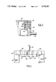
- FIG. 5 is a schematic plan view of an installation for carrying out the process according to the invention, showing in particular the circulation of the impressions, frames and beams and the implantation of the different work stations corresponding to each of the steps of the process.
- FIG. 1 shows the impression 100 and the prestress frame 200, these two elements being separated but superposed opposite each other in a position prior to being assembled together.
- the impression 100 has an inner surface 110 forming the mould proper, and of which the shape corresponds to the shape to be given to the beam.
- This mould proper is reinforced and supported by two lateral walls 120 borne by a base 130.
- the two ends 140 of the impression are open; they each present an end surface 141 adapted to receive a corresponding element of the frame ensuring hermetic closure of the mould.
- the impression also comprises, in its lower part, transverse recesses 150 allowing, for example, introduction of the fork of a fork lift truck or other handling apparatus; such handling is also facilitated by the presence of journals such as 160, disposed inside the impression (and therefore only accessible when said impression is turned over and does not rest on its base) in order not to hinder positioning of the prestress frame.
- This frame 200 is constituted by two longitudinal elements 210 connecting two end walls 220.
- These end walls 220 each comprise a series of bores such as 230 (in the example shown, seven of such bores have been provided): the reinforcements (not shown) are placed between the opposite bores of each end wall, and tensioned by means of devices disposed on the outer face of the end walls, such as for example studs for screwing, according to a known technique.
- the considerable force of tension of the reinforcements which pull the two end walls towards each other, makes it necessary to provide sufficiently resistant sections 210 to avoid any buckling and twisting of the frame.
- These sections may for example be adequately dimensioned, standardized U-shaped sections.
- Each end wall also comprises, for handling the frame, a journal 240 and blind holes 250 disposed on the outer face. Finally, to allow positioning and ensure tightness between the frame and the impression, each end wall is provided, on its inner face, with a boss 221 whose profile is homologous of that of the end surface 141 of the impression.
- FIG. 2 shows the profile 222 of the boss 221, corresponding to the bottom and to the sides of the end surface 141 of the impression 100.
- the inner surface 211 of the longitudinal element 210 is homologous of the outer surface 121 of the side wall 120 of the impression, and the lower face 212 of this same longitudinal element corresponds to the upper face 131 of the base 130.
- the simple positioning of frame 200 on impression 100 ensures strict positioning of these two elements and tightness of the mould, made simply by contact of the corresponding faces.
- the frame and the impression are fastened together, for example by means of hydraulic clipping jaws bearing between the upper face 213 of each longitudinal element and the lower face 132 of the base of the impression.
- FIGS. 3 and 4 show the structure of each end wall 220 more precisely. They are rigidly fixed to the ends of the longitudinal elements 210, for example by welding.
- the end wall 220 and its boss 221 have bores 230 passing therethrough for the passage and tensioning of the reinforcements. Certain of these bores comprise, on the outer face, a facing 231 for concealing the pieces retaining the reinforcements.
- the bores provided with a facing on one of the end walls are not provided with facings on the opposite end wall, and vice versa. In this way, the studs for screwing may be distributed on the two end walls and a sufficient space may thus be available around each stud, despite the small space between the axes of the bores.
- FIGS. 3 and 4 also show the journal 240 and the blind holes 250 allowing handling.
- the journals which are oriented axially, are preferably disposed in the lower part of the end wall, so as to allow the assembly to be turned over, around an axis passing through these journals; to this end, it suffices for this axis to pass below the centre of gravity of the assembly formed by the impression, the frame and the mass of concrete.
- FIG. 5 is a plan of an installation for carrying out the process, which shows, in particular, the circulation of the impressions, the frames and beams, and the implantation of the different stations corresponding to each of the steps of the process. Manufacture of a beam will now be described with reference to this Figure.
- the installation firstly comprises stations for mounting the reinforcements in the frames (for example two, referenced 300 in FIG. 5). At these stations, the reinforcements are installed inside the frame, and the tensioning pieces which retain them are positioned.
- the frames 201 thus prepared are then taken to tensioning stations 310, provided with appropriate safety devices. This tensioning is effected by tightening the screwing studs located on either side of the frames.
- the frames 202 thus prepared and tensioned are then taken to a station 320 for mounting the impressions in the frames, as well as for lubricating the impressions for facilitating subsequent demoulding.
- a station 320 for mounting the impressions in the frames, as well as for lubricating the impressions for facilitating subsequent demoulding.
- the mould assembly (frame and impression combined) then passes into a station 330 for turning over through 180°, so that the opening of the mould is directed upwardly.
- the mould is then ready to receive the liquid concrete.
- the mould is filled at a casting station 340, supplied with liquid concrete previously prepared by a mixer 350.
- This casting station is of a type comparable with the one described in Applicants' French Pat. No. 72 20628. It will be particularly noted that, during this operation as during the following one, the frame and the impression are held firmly together by means of hydraulic clipping jaws, so as to complete the tightness, ensured by simple contact as indicated hereinbefore.
- the filled mould is then disposed on a vibrating table 360 which ensures ramming of the concrete.
- This vibrating table is similar to the one described in Applicant's French Pat. No. 79 10058.
- the full, rammed moulds are then evacuated by a truck 502 towards one of the storage and curing areas 370.
- a truck 502 towards one of the storage and curing areas 370.
- five of such areas have been shown, all identical.
- the moulds are juxtaposed therein, side by side.
- Demoulding is effected by a demoulding assembly 380 similar to the one described in Applicants' French Pat. No. 72 21991. Demoulding is effected after the frames have been turned over. The concrete beam therefore rests with its upper face placed on the heating slab, and it is then easy to withdraw the impression from the frame without displacing the latter nor the beam. The removal of the impression from within the confines of the frame leaves an air gap between the longitudinal sides of the frame and the beam being cast. The withdrawn impressions are then returned to the station 320 for re-mounting on the frames, for example by means of a carriage 503.
- a cover unit 390 mounted on a travelling crane 400, then covers all the demoulded beams located in the same storage area with a cover which will allow curing in a confined atmosphere; the storage areas 370 are in fact constituted by heating slabs, heating preferably being ensured by electrical means.
- a truck 504 evacuates the cured frames, preferably in two's (the frames are, in fact, lighter due to the withdrawal of the impressions). These frames, which retain the dry beams, are taken towards lines 410 awaiting detensioning of the reinforcements, this operation being effected at stations referenced 420. The frames are then separated from the finished beams at stations 430 where the ends of the reinforcements, imprisoned in the concrete, are cut. The empty frames 203 are then returned towards the reinforcement mounting stations 300 for subsequent use.
- the beams are stored on a finishing line 440 before being packed at a station 450 from which they will be evacuated towards a depot by means of a fork lift truck 505.
Landscapes
- Engineering & Computer Science (AREA)
- Manufacturing & Machinery (AREA)
- Chemical & Material Sciences (AREA)
- Ceramic Engineering (AREA)
- Mechanical Engineering (AREA)
- Manufacturing Of Tubular Articles Or Embedded Moulded Articles (AREA)
- Moulds, Cores, Or Mandrels (AREA)
- Footwear And Its Accessory, Manufacturing Method And Apparatuses (AREA)
Applications Claiming Priority (2)
| Application Number | Priority Date | Filing Date | Title |
|---|---|---|---|
| FR820086 | 1982-01-21 | ||
| FR8200886A FR2519898B1 (fr) | 1982-01-21 | 1982-01-21 | Ensemble de moulage d'elements en beton arme precontraint, notamment de traverses, et procede de fabrication de ces elements |
Related Parent Applications (1)
| Application Number | Title | Priority Date | Filing Date |
|---|---|---|---|
| US06762798 Continuation | 1985-08-02 |
Publications (1)
| Publication Number | Publication Date |
|---|---|
| US4758393A true US4758393A (en) | 1988-07-19 |
Family
ID=9270191
Family Applications (1)
| Application Number | Title | Priority Date | Filing Date |
|---|---|---|---|
| US06/946,125 Expired - Fee Related US4758393A (en) | 1982-01-21 | 1986-12-23 | Process for casting elements in reinforced concrete |
Country Status (5)
| Country | Link |
|---|---|
| US (1) | US4758393A (it) |
| AU (1) | AU553381B2 (it) |
| FR (1) | FR2519898B1 (it) |
| GB (1) | GB2113600B (it) |
| IT (1) | IT1167111B (it) |
Cited By (11)
| Publication number | Priority date | Publication date | Assignee | Title |
|---|---|---|---|---|
| US5114653A (en) * | 1985-11-07 | 1992-05-19 | Akzo N.V. | Processes of manufacturing prestressed concrete |
| DE19708734A1 (de) * | 1997-03-04 | 1998-09-24 | Dorstener Maschf Ag | Verfahren und Vorrichtung zum Herstellen von plattenförmigen oder balkenförmigen Stahlbetonteilen, insbesondere von Stahlbetonschwellen |
| US6155810A (en) * | 1996-03-11 | 2000-12-05 | Abetone Teknik Ab | Mould bed for manufacturing pre-stressed concrete elements |
| US6773650B1 (en) | 2001-03-21 | 2004-08-10 | Power Poles, Inc. | Prestressed concrete casting apparatus and method |
| DE4427401B4 (de) * | 1994-08-03 | 2005-05-04 | Pfleiderer Infrastrukturtechnik Gmbh & Co. Kg | Vorrichtung zur Herstellung von im wesentlichen stabförmigen Spannbetonfertigteilen, vornehmlich Schwellen |
| EP1360397B2 (de) † | 2001-02-14 | 2009-11-11 | Max Bögl Bauunternehmung GmbH & Co. KG | Verfahren und palette zur herstellung eines präzisen betonfertigteiles |
| US20100181699A1 (en) * | 2007-02-20 | 2010-07-22 | Rail.One Gmbh | Concrete sleeper and method for producing the same |
| WO2011008783A1 (en) | 2009-07-14 | 2011-01-20 | 21St Century Structures, Llc | Movable pallet and method of use |
| US9051745B1 (en) | 2013-11-19 | 2015-06-09 | Kevin Parr | Telescoping concrete form assembly |
| CN104802305A (zh) * | 2015-04-28 | 2015-07-29 | 山东久同工业技术有限公司 | 预应力张拉平台 |
| US9340933B2 (en) | 2013-11-19 | 2016-05-17 | Kevin Parr | Telescoping concrete form assembly |
Families Citing this family (12)
| Publication number | Priority date | Publication date | Assignee | Title |
|---|---|---|---|---|
| AU575808B2 (en) * | 1983-03-15 | 1988-08-11 | Aubrey John Weston Harrison | Prestressed concrete articles with strap reinforcements |
| DE3440247A1 (de) * | 1984-11-03 | 1986-05-22 | Wayss & Freytag Ag, 6000 Frankfurt | Schalung fuer serienfertigteile aus stahlbeton, vornehmlich fuer vorgespannte weichenschwellen |
| IT1206781B (it) * | 1987-04-29 | 1989-05-03 | Scac Spa | Impianto per la fabbricazione di manufatti lineari in cemento armato precompresso. |
| FR2644722B1 (fr) * | 1989-03-22 | 1993-05-28 | Vagneux Traverses Beton Arme S | Procede de moulage d'un jeu de traverses ferroviaires en beton arme, notamment pour appareil de voie, moule a cet effet et traverses obtenues par ce procede |
| DE3931201C1 (en) * | 1989-09-19 | 1990-11-22 | Wayss & Freytag Ag, 6000 Frankfurt, De | Concrete railway sleepers mfr. - uses moving frame mechanism which releases each sleeper immediately |
| FR2657382B1 (fr) * | 1990-01-22 | 1996-07-19 | Rector Sa | Module independant de fabrication de beton precontraint et son procede de mise en óoeuvre. |
| DE4143190C2 (de) * | 1991-01-05 | 1994-09-01 | Stewing Stahl & Anlagenbau | Gießform aus Stahl zum Herstellen von vorgespannten Betonschwellen |
| DE4203895C2 (de) * | 1992-02-11 | 1996-08-29 | Dyckerhoff & Widmann Ag | Einrichtung zum Herstellen von Fertigbauteilen aus Spannbeton mit sofortigem Verbund, insbesondere von Spannbetonschwellen |
| ES2050650T1 (es) * | 1992-10-08 | 1994-06-01 | Wayss & Freytag Ag | Encofrado circundante para piezas acabadas de hormigon pretensado. |
| DE102009016804A1 (de) * | 2009-04-09 | 2010-10-14 | Stephan Sehliger | Schalung für Präzisions-Betonteile |
| CZ304279B6 (cs) * | 2010-09-14 | 2014-02-12 | Václav Nevřiva | Způsob výroby předem předpjatých monolitických železobetonových konstrukcí a zařízení k provádění způsobu |
| DE102017011427A1 (de) * | 2017-12-12 | 2019-06-13 | Spitzke Fahrwegsysteme GmbH | Verfahren zur Herstellung einer Spannbetonschwelle |
Citations (12)
| Publication number | Priority date | Publication date | Assignee | Title |
|---|---|---|---|---|
| US2236107A (en) * | 1938-03-04 | 1941-03-25 | Joseph E Miller | Concrete pipe |
| GB609527A (en) * | 1946-03-11 | 1948-10-01 | London And North Eastern Railw | Improvements in the mass production of reinforced concrete constructions |
| GB711203A (en) * | 1949-02-14 | 1954-06-30 | Mini Of Works | Improvements relating to the production of components of prestressed concrete |
| US3233027A (en) * | 1961-12-20 | 1966-02-01 | Wennstrom Elof | Method of making prestressed concrete beams |
| US3568274A (en) * | 1968-04-16 | 1971-03-09 | Little Inc A | Apparatus for making prestressed concrete members |
| US3666385A (en) * | 1969-07-03 | 1972-05-30 | Robert S Baker | Apparatus for making prestressed concrete members |
| US3810337A (en) * | 1970-10-28 | 1974-05-14 | S Pollard | An elongated stressed structural member |
| US3891731A (en) * | 1969-10-20 | 1975-06-24 | Chester I Williams | Method of pre-stressing form tie systems |
| US3907951A (en) * | 1971-10-06 | 1975-09-23 | Modular Wall Systems Inc | Method of forming concrete panels using electrically heated mold |
| US4069283A (en) * | 1976-04-05 | 1978-01-17 | Rauchfuss Arthur A | Method of curing and protecting a concrete column |
| US4224274A (en) * | 1978-06-19 | 1980-09-23 | Ozawa Concrete Industry Co., Ltd. | Method for manufacture of concrete products |
| US4629408A (en) * | 1985-09-06 | 1986-12-16 | Arctic Equipment Rental, Inc. | Portable concrete beam harping system |
-
1982
- 1982-01-21 FR FR8200886A patent/FR2519898B1/fr not_active Expired
- 1982-12-30 GB GB08236919A patent/GB2113600B/en not_active Expired
- 1982-12-30 AU AU91939/82A patent/AU553381B2/en not_active Ceased
-
1983
- 1983-01-18 IT IT47573/83A patent/IT1167111B/it active
-
1986
- 1986-12-23 US US06/946,125 patent/US4758393A/en not_active Expired - Fee Related
Patent Citations (12)
| Publication number | Priority date | Publication date | Assignee | Title |
|---|---|---|---|---|
| US2236107A (en) * | 1938-03-04 | 1941-03-25 | Joseph E Miller | Concrete pipe |
| GB609527A (en) * | 1946-03-11 | 1948-10-01 | London And North Eastern Railw | Improvements in the mass production of reinforced concrete constructions |
| GB711203A (en) * | 1949-02-14 | 1954-06-30 | Mini Of Works | Improvements relating to the production of components of prestressed concrete |
| US3233027A (en) * | 1961-12-20 | 1966-02-01 | Wennstrom Elof | Method of making prestressed concrete beams |
| US3568274A (en) * | 1968-04-16 | 1971-03-09 | Little Inc A | Apparatus for making prestressed concrete members |
| US3666385A (en) * | 1969-07-03 | 1972-05-30 | Robert S Baker | Apparatus for making prestressed concrete members |
| US3891731A (en) * | 1969-10-20 | 1975-06-24 | Chester I Williams | Method of pre-stressing form tie systems |
| US3810337A (en) * | 1970-10-28 | 1974-05-14 | S Pollard | An elongated stressed structural member |
| US3907951A (en) * | 1971-10-06 | 1975-09-23 | Modular Wall Systems Inc | Method of forming concrete panels using electrically heated mold |
| US4069283A (en) * | 1976-04-05 | 1978-01-17 | Rauchfuss Arthur A | Method of curing and protecting a concrete column |
| US4224274A (en) * | 1978-06-19 | 1980-09-23 | Ozawa Concrete Industry Co., Ltd. | Method for manufacture of concrete products |
| US4629408A (en) * | 1985-09-06 | 1986-12-16 | Arctic Equipment Rental, Inc. | Portable concrete beam harping system |
Cited By (15)
| Publication number | Priority date | Publication date | Assignee | Title |
|---|---|---|---|---|
| US5114653A (en) * | 1985-11-07 | 1992-05-19 | Akzo N.V. | Processes of manufacturing prestressed concrete |
| DE4427401B4 (de) * | 1994-08-03 | 2005-05-04 | Pfleiderer Infrastrukturtechnik Gmbh & Co. Kg | Vorrichtung zur Herstellung von im wesentlichen stabförmigen Spannbetonfertigteilen, vornehmlich Schwellen |
| US6155810A (en) * | 1996-03-11 | 2000-12-05 | Abetone Teknik Ab | Mould bed for manufacturing pre-stressed concrete elements |
| DE19708734A1 (de) * | 1997-03-04 | 1998-09-24 | Dorstener Maschf Ag | Verfahren und Vorrichtung zum Herstellen von plattenförmigen oder balkenförmigen Stahlbetonteilen, insbesondere von Stahlbetonschwellen |
| DE19708734C2 (de) * | 1997-03-04 | 2001-05-31 | Dorstener Maschf Ag | Verfahren und Vorrichtung zum Herstellen von plattenförmigen oder balkenförmigen Stahlbetonteilen, insbesondere von Stahlbetonschwellen |
| EP1360397B2 (de) † | 2001-02-14 | 2009-11-11 | Max Bögl Bauunternehmung GmbH & Co. KG | Verfahren und palette zur herstellung eines präzisen betonfertigteiles |
| US7137800B1 (en) | 2001-03-21 | 2006-11-21 | Power Poles, Inc. | Prestressed concrete casting apparatus and method |
| US6773650B1 (en) | 2001-03-21 | 2004-08-10 | Power Poles, Inc. | Prestressed concrete casting apparatus and method |
| US20100181699A1 (en) * | 2007-02-20 | 2010-07-22 | Rail.One Gmbh | Concrete sleeper and method for producing the same |
| WO2011008783A1 (en) | 2009-07-14 | 2011-01-20 | 21St Century Structures, Llc | Movable pallet and method of use |
| US20110012288A1 (en) * | 2009-07-14 | 2011-01-20 | Joseph Gallione | Movable Pallet and Method of Use |
| US9051745B1 (en) | 2013-11-19 | 2015-06-09 | Kevin Parr | Telescoping concrete form assembly |
| WO2015077230A3 (en) * | 2013-11-19 | 2015-12-30 | Kevin Parr | Concrete form assembly |
| US9340933B2 (en) | 2013-11-19 | 2016-05-17 | Kevin Parr | Telescoping concrete form assembly |
| CN104802305A (zh) * | 2015-04-28 | 2015-07-29 | 山东久同工业技术有限公司 | 预应力张拉平台 |
Also Published As
| Publication number | Publication date |
|---|---|
| GB2113600A (en) | 1983-08-10 |
| FR2519898B1 (fr) | 1987-08-28 |
| AU553381B2 (en) | 1986-07-10 |
| FR2519898A1 (fr) | 1983-07-22 |
| GB2113600B (en) | 1985-10-02 |
| IT1167111B (it) | 1987-05-13 |
| IT8347573A0 (it) | 1983-01-18 |
| IT8347573A1 (it) | 1984-07-18 |
| AU9193982A (en) | 1983-07-28 |
Similar Documents
| Publication | Publication Date | Title |
|---|---|---|
| US4758393A (en) | Process for casting elements in reinforced concrete | |
| CN108858723B (zh) | 公路预制箱梁新型集约化施工工艺 | |
| US2495100A (en) | Apparatus for making precast concrete units | |
| US3523997A (en) | Method of curing elongated concrete articles | |
| US4421710A (en) | Method, devices, mold bearing structures and installations for improving the efficiency of processes for the manufacture of prestressed concrete products | |
| DE19836320C2 (de) | Verfahren und Vorrichtung zur variablen Fertigung von Betonschwellen | |
| US4228985A (en) | Apparatus for producing molded concrete products | |
| DE3210588A1 (de) | Giessform zum herstellen von metallgussstuecken | |
| US5507996A (en) | Method and apparatus for manufacturing building blocks from a hydraulic binder such as plaster, an inert filler such as sand, and water | |
| CA1043078A (en) | Apparatus for producing concrete reinforced ties | |
| EP0999021A2 (en) | Pressure casting line for sanitary articles, and relative mould | |
| US3758067A (en) | Movable multiple casting moulds and elements therefor | |
| US4126655A (en) | Method and apparatus for manufacturing concrete elements | |
| CA2212644A1 (en) | An apparatus and method to manufacture cast panels | |
| CA3016992A1 (en) | Method and layout for producing hollow concrete elements | |
| US2983021A (en) | Processes and apparatus for the manufacture of concrete articles, particularly of reinforced concrete | |
| US2968082A (en) | Mold assemblies | |
| SE8502923D0 (sv) | Gas permeable metal casting mold having gas collection voids | |
| US3798300A (en) | Method for producing cast three dimensional building components | |
| US4409159A (en) | Moulding reinforced concrete articles | |
| US2240776A (en) | Apparatus for making concrete blocks | |
| USRE31753E (en) | Method of hollow article casting | |
| FR2573697A1 (fr) | Procede et installation de fabrication d'elements en beton | |
| US4439131A (en) | Apparatus for producing concrete elements of high dimensional accuracy | |
| EP0053587B1 (en) | Shuttering for the fabrication of two-slab panels |
Legal Events
| Date | Code | Title | Description |
|---|---|---|---|
| FEPP | Fee payment procedure |
Free format text: PAYOR NUMBER ASSIGNED (ORIGINAL EVENT CODE: ASPN); ENTITY STATUS OF PATENT OWNER: LARGE ENTITY |
|
| FPAY | Fee payment |
Year of fee payment: 4 |
|
| FPAY | Fee payment |
Year of fee payment: 8 |
|
| REMI | Maintenance fee reminder mailed | ||
| LAPS | Lapse for failure to pay maintenance fees | ||
| FP | Lapsed due to failure to pay maintenance fee |
Effective date: 20000719 |
|
| STCH | Information on status: patent discontinuation |
Free format text: PATENT EXPIRED DUE TO NONPAYMENT OF MAINTENANCE FEES UNDER 37 CFR 1.362 |