US4763965A - Printer table with a paper carriage - Google Patents
Printer table with a paper carriage Download PDFInfo
- Publication number
- US4763965A US4763965A US06/886,025 US88602586A US4763965A US 4763965 A US4763965 A US 4763965A US 88602586 A US88602586 A US 88602586A US 4763965 A US4763965 A US 4763965A
- Authority
- US
- United States
- Prior art keywords
- paper
- printer table
- printer
- wide side
- paper carriage
- Prior art date
- Legal status (The legal status is an assumption and is not a legal conclusion. Google has not performed a legal analysis and makes no representation as to the accuracy of the status listed.)
- Expired - Fee Related
Links
Images

Classifications
-
- B—PERFORMING OPERATIONS; TRANSPORTING
- B41—PRINTING; LINING MACHINES; TYPEWRITERS; STAMPS
- B41J—TYPEWRITERS; SELECTIVE PRINTING MECHANISMS, i.e. MECHANISMS PRINTING OTHERWISE THAN FROM A FORME; CORRECTION OF TYPOGRAPHICAL ERRORS
- B41J11/00—Devices or arrangements of selective printing mechanisms, e.g. ink-jet printers or thermal printers, for supporting or handling copy material in sheet or web form
- B41J11/58—Supply holders for sheets or fan-folded webs, e.g. shelves, tables, scrolls, pile holders
Definitions
- the invention relates to a printer table with a paper carriage, where the paper carriage is capable of being inserted under the printer table.
- An object of the present invention is to provide a printer table with a paper carriage which can be constructed so that, at least, four grades of paper can be held in readiness without difficulty; each of them properly arranged for feeding.
- a printer table having a bottom frame open at one wide side, with a traverse element at the opposite wide side and vertical posts at the four corners of the bottom frame.
- the width of the paper carriage corresponds to the distance between the two posts of the printer table which define the limits of the open wide side.
- the paper carriage has one or more base plates with raised edges.
- the invention differs from the state of the art in that the paper carriage can be manipulated without effort. Different kinds of paper are held in readiness. To change to another kind of paper, all that is necessary is withdrawal of the paper carriage, which moves with ease on casters or rollers, and to introduce the paper carriage into a new alignment. The various sizes of paper are constrained to be arranged on the paper carriage properly and ready for feeding. A single alignment of the printer on the table thus guarantees the permanent alignment of the printer in the correct position. The manipulation of the individual and relatively heavy stacks of paper, when changing paper or paper size, is no longer necessary.
- the invention provides that the transverse bars of the bottom frame project beyond the posts on the side opposite the open wide side and are connected, at their ends, by a traverse element serving as a stop for the paper carriage.
- a proper and orderly depositing of the printer paper is possible by having the traverse element carry a reception plate.
- the space required by the printer table for stowing is reduced by having the reception plate pivotable on folding hinges. In this manner, the printer table can be easily stowed away.
- An orderly depositing of differnt sizes of printed paper is rendered possible by having guide rails with one or two insertions, or slide-in grooves arranged on the reception plate; two of such guide rails, each with two insertion grooves, being arranged opposite to one another and one guide rail, with one insertion groove, being in an intermediate region, and being positioned opposite one of the two aforesaid guide rails.
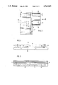
- FIG. 1 is a side view of a printer table of the invention with a paper carriage
- FIG. 2 is a front view corresponding to FIG. 1;
- FIG. 3 is a plan view corresponding to FIG. 1;
- FIG. 4 is a view of the reception plate as viewed in the direction of arrow IV.
- FIG. 5 is a sectional view taken along line V.
- FIG. 1 shows a printer table 1 with a bottom frame 2, vertical posts 3, in the four corners of bottom frame 2, an upper frame 4 and a table plate 5.
- the bottom frame 2 comprises two transverse bars 6 arranged opposite each other, each of which projects on one side beyond a post 3.
- a traverse element 7, connects traverse bars 6 and is offset from posts 3 by the length, or projection, of traverse bars 6.
- the bottom frame is open at the side opposite the traverse element so that, in accordance with FIG. 2, the entire space below the upper frame 4 is readily and freely accessible.
- Rollers 8 are mounted on the bottom frame 2 in the vicinity of traverse element 7. At the opposite and open side of the bottom frame, posts 3 are extended by supporting legs 9. If desired, rollers may also be provided there.
- Table plate 5 holds a printer 10, which is represented by a dot-dash line.
- Printer 10 is aligned along one edge of the table plate 5. According to FIG. 2, printer 10 is aligned on the right-hand edge of printer table 1.
- the folding hinges 12 carry a reception plate 13, which holds a drawer for the printer paper coming from the printer. This will be further explained in detail below.
- the folding hinges 12 each have one stop so that the reception plate 13 is positioned in the horizontal alignment, as shown in FIG. 1.
- the reception plate 13 can be folded upward in the direction of arrow 14.
- a paper carriage 15 comprises a frame construction with four posts 16 and a plurality of bottom, or base plates 17, whose frames 18, are each surrounded by raised edges 19.
- the raised edges 19 exist as a continuous periphery on all four sides of each base plate 17.
- the frame 18 is preferably constructed from L-shaped angle rods.
- the paper carriage 15 stands on four rollers 20 so that paper carriage 15 can be moved.
- the height and the width of paper carriage 15 are adapted to the size of the opening existing at the open side of the bottom frame 2, beneath upper frame 4 of printer table 1 so that the paper carriage can be inserted into printer table 1 from the open side without effort, and there is room for it within the printer table, as can be seen from FIGS. 1 to 3.
- Each base plate 17 of the paper carriage 15 accepts two stacks of paper 21, 22, 23, 24 of different sizes.
- the stacks of paper comprise, in the usual manner, contiguous and folded sheets of paper in continuous form. It may be seen from the Figure that the papers have differnt sizes.
- Each stack of paper may also be placed on the base plate 17 together with the packaging carton.
- Each stack of paper is set in place, at one corner of the paper carriage, at raised edges 19, so that the particular stack of paper is aligned on one corner of the paper carriage.
- one stack of paper (22 or 24) is aligned on the printer 10, ready to feed, and the paper may, in each case, be introduced into the printer 10 in the proper position.
- paper from the stack of paper 22 or 24 can be fed to the printer 10.
- the paper runs over the table edge without obstruction since the paper carriage 15, positioned against the transverse element 7, projects beyond the edge of the table.
- a single adjustment is sufficient in order to assure a feed in the proper position. If the stacks of paper 21 or 23 are to be used, it is only necessary that the paper carriage 15 be withdrawn from the printer table and rotated 180. After that, the paper carriage is again moved into the printer table.
- the paper is guided from the stack of paper 22 to the printer 10 in the usual manner, and it proceeds out of the printer in the printer condition.
- the continuous paper then moves to the reception late 13.
- FIGS. 1 through 3 show the different paper sizes. Normally, two paper sizes are used. Corresponding to these paper sizes, drawers are available to the user, which drawers can be stored in file cabinets. The reception plate is contructed for the reception of each of these drawers.
- guide rails 25, 26 and 27 are arranged on the reception plate 13.
- Guide rails 25 and 26 are of the same construction and have two guide grooves 28.
- the guide rail 27 has only one guide groove 29, which is adapted in height to the lower guide groove 28.
- stop noses (or projections) 30 are provided in each case.
- the guide rails 25 and 26 are arranged at a distance from each other which corresponds to the dimensions of a drawer 31, as indicated schematically in FIG. 4.
- Drawer 31 is provided for holding paper having a width of 390 mm. According to the illustration of FIG. 4, drawer 31 is inserted in each case into the upper guide grooves.
- Guide rail 27 is opposite guide rail 26 at a distance from it such that drawer 31 for paper, having a width of 250 mm, can be inserted into the guide grooves 28 and 29.
- Guide groove 29 is aligned to the lower guide groove 28.
Landscapes
- Sheets, Magazines, And Separation Thereof (AREA)
- Handcart (AREA)
- Unwinding Webs (AREA)
- Pile Receivers (AREA)
- Accessory Devices And Overall Control Thereof (AREA)
Applications Claiming Priority (2)
| Application Number | Priority Date | Filing Date | Title |
|---|---|---|---|
| DE3531188 | 1985-08-31 | ||
| DE19853531188 DE3531188A1 (de) | 1985-08-31 | 1985-08-31 | Druckertisch mit papierwagen |
Publications (1)
| Publication Number | Publication Date |
|---|---|
| US4763965A true US4763965A (en) | 1988-08-16 |
Family
ID=6279863
Family Applications (1)
| Application Number | Title | Priority Date | Filing Date |
|---|---|---|---|
| US06/886,025 Expired - Fee Related US4763965A (en) | 1985-08-31 | 1986-07-15 | Printer table with a paper carriage |
Country Status (4)
| Country | Link |
|---|---|
| US (1) | US4763965A (de) |
| EP (1) | EP0214386B1 (de) |
| AT (1) | ATE66869T1 (de) |
| DE (2) | DE3531188A1 (de) |
Cited By (3)
| Publication number | Priority date | Publication date | Assignee | Title |
|---|---|---|---|---|
| USD326967S (en) | 1989-05-30 | 1992-06-16 | Bardelang Wayne A | Cabinet for electronic equipment |
| USD415791S (en) * | 1997-12-16 | 1999-10-26 | Hewlett-Packard Company | Printer stand |
| US6126253A (en) * | 1997-04-17 | 2000-10-03 | Sligh Furniture Company | Computer desk |
Citations (11)
| Publication number | Priority date | Publication date | Assignee | Title |
|---|---|---|---|---|
| US739662A (en) * | 1903-04-08 | 1903-09-22 | Mary E Francisco | Exhibiting-box. |
| GB477158A (en) * | 1936-06-23 | 1937-12-23 | Betjemann & Sons Ltd G | Improvements in cocktail and like cabinets |
| DE800898C (de) * | 1949-07-12 | 1950-12-14 | Otto Wulf | Schreibtisch |
| DE829776C (de) * | 1949-11-22 | 1952-01-28 | Fritz Schumacher | Schreibtisch, insbesondere Bueroschreibtisch |
| US2657968A (en) * | 1950-01-06 | 1953-11-03 | Mengel Company | Drawer slide for cabinets |
| AT226911B (de) * | 1960-08-24 | 1963-04-25 | Fortschritt Bueroeinr Fab Gmbh | Schreib- oder Arbeitstisch |
| JPS5828394A (ja) * | 1981-08-12 | 1983-02-19 | Usac Electronics Ind Co Ltd | プリンタ装置における帳票台 |
| JPS58224770A (ja) * | 1982-06-24 | 1983-12-27 | Usac Electronics Ind Co Ltd | 連帳用紙の供給方法 |
| DE3346840A1 (de) * | 1983-12-23 | 1985-07-11 | Siemens AG, 1000 Berlin und 8000 München | Herausziehbare ablagevorrichtung fuer eine vorgefaltete papierbahn in einem papierstapler einer schnelldruckeinrichtung |
| EP0168885A1 (de) * | 1984-07-20 | 1986-01-22 | Partners Data B.V. | Papierablage und -zufuhr für Computerdrucker |
| WO1986003458A1 (en) * | 1984-12-12 | 1986-06-19 | Alston Engineers (Preston) Limited | Printer support unit |
-
1985
- 1985-08-31 DE DE19853531188 patent/DE3531188A1/de not_active Withdrawn
-
1986
- 1986-06-26 AT AT86108710T patent/ATE66869T1/de not_active IP Right Cessation
- 1986-06-26 EP EP86108710A patent/EP0214386B1/de not_active Expired - Lifetime
- 1986-06-26 DE DE8686108710T patent/DE3681236D1/de not_active Expired - Fee Related
- 1986-07-15 US US06/886,025 patent/US4763965A/en not_active Expired - Fee Related
Patent Citations (11)
| Publication number | Priority date | Publication date | Assignee | Title |
|---|---|---|---|---|
| US739662A (en) * | 1903-04-08 | 1903-09-22 | Mary E Francisco | Exhibiting-box. |
| GB477158A (en) * | 1936-06-23 | 1937-12-23 | Betjemann & Sons Ltd G | Improvements in cocktail and like cabinets |
| DE800898C (de) * | 1949-07-12 | 1950-12-14 | Otto Wulf | Schreibtisch |
| DE829776C (de) * | 1949-11-22 | 1952-01-28 | Fritz Schumacher | Schreibtisch, insbesondere Bueroschreibtisch |
| US2657968A (en) * | 1950-01-06 | 1953-11-03 | Mengel Company | Drawer slide for cabinets |
| AT226911B (de) * | 1960-08-24 | 1963-04-25 | Fortschritt Bueroeinr Fab Gmbh | Schreib- oder Arbeitstisch |
| JPS5828394A (ja) * | 1981-08-12 | 1983-02-19 | Usac Electronics Ind Co Ltd | プリンタ装置における帳票台 |
| JPS58224770A (ja) * | 1982-06-24 | 1983-12-27 | Usac Electronics Ind Co Ltd | 連帳用紙の供給方法 |
| DE3346840A1 (de) * | 1983-12-23 | 1985-07-11 | Siemens AG, 1000 Berlin und 8000 München | Herausziehbare ablagevorrichtung fuer eine vorgefaltete papierbahn in einem papierstapler einer schnelldruckeinrichtung |
| EP0168885A1 (de) * | 1984-07-20 | 1986-01-22 | Partners Data B.V. | Papierablage und -zufuhr für Computerdrucker |
| WO1986003458A1 (en) * | 1984-12-12 | 1986-06-19 | Alston Engineers (Preston) Limited | Printer support unit |
Cited By (3)
| Publication number | Priority date | Publication date | Assignee | Title |
|---|---|---|---|---|
| USD326967S (en) | 1989-05-30 | 1992-06-16 | Bardelang Wayne A | Cabinet for electronic equipment |
| US6126253A (en) * | 1997-04-17 | 2000-10-03 | Sligh Furniture Company | Computer desk |
| USD415791S (en) * | 1997-12-16 | 1999-10-26 | Hewlett-Packard Company | Printer stand |
Also Published As
| Publication number | Publication date |
|---|---|
| DE3681236D1 (de) | 1991-10-10 |
| EP0214386A2 (de) | 1987-03-18 |
| EP0214386B1 (de) | 1991-09-04 |
| EP0214386A3 (en) | 1987-09-02 |
| ATE66869T1 (de) | 1991-09-15 |
| DE3531188A1 (de) | 1987-03-12 |
Similar Documents
| Publication | Publication Date | Title |
|---|---|---|
| CA1042974A (en) | Document handling system | |
| US4923188A (en) | Z-fold paper sheet carrier | |
| US4755010A (en) | Computer work station and printer cabinet | |
| US5385399A (en) | Document storage and display cabinet | |
| US4515490A (en) | Computer printer stand with multiple paper web guide slots | |
| EP0121906A2 (de) | Papierzufuhrsystem für Kopiergerät | |
| EP1046363A2 (de) | Halter für blattförmige Gegenstände | |
| US4763965A (en) | Printer table with a paper carriage | |
| DE19655031B4 (de) | Dokumentenscanvorrichtung | |
| US4059256A (en) | Loading rack for minicomputer | |
| CA2101612C (en) | Adjustable suspension system for hanging folders and package therefor | |
| JPH0819439A (ja) | 書類整理箱等の連結方法 | |
| US5106051A (en) | Box for supporting a printer | |
| US5380079A (en) | Storing device having upper and lower rod separators | |
| CN206441287U (zh) | 一种用于学校图书馆的自助借、还书装置 | |
| CN206252220U (zh) | 一种轻型角钢仓储货架 | |
| CN219249486U (zh) | 一种智慧教室讲桌 | |
| US4860904A (en) | Paper stacker | |
| US2912241A (en) | Corner separator mechanism for duplicators | |
| DE20319443U1 (de) | Funktionsplatte für Schreibtischaccessoires | |
| CN217986994U (zh) | 一种具有进出纸方向可调扫描仪的服务台 | |
| CN220008964U (zh) | 一种压合式糊箱机进料装置 | |
| JPS5828394A (ja) | プリンタ装置における帳票台 | |
| JPH0328020Y2 (de) | ||
| US4305520A (en) | Record storage apparatus |
Legal Events
| Date | Code | Title | Description |
|---|---|---|---|
| FEPP | Fee payment procedure |
Free format text: PAYOR NUMBER ASSIGNED (ORIGINAL EVENT CODE: ASPN); ENTITY STATUS OF PATENT OWNER: SMALL ENTITY |
|
| FPAY | Fee payment |
Year of fee payment: 4 |
|
| REMI | Maintenance fee reminder mailed | ||
| LAPS | Lapse for failure to pay maintenance fees | ||
| FP | Lapsed due to failure to pay maintenance fee |
Effective date: 19960821 |
|
| STCH | Information on status: patent discontinuation |
Free format text: PATENT EXPIRED DUE TO NONPAYMENT OF MAINTENANCE FEES UNDER 37 CFR 1.362 |