US4786868A - Speed control unit - Google Patents
Speed control unit Download PDFInfo
- Publication number
- US4786868A US4786868A US06/904,120 US90412086A US4786868A US 4786868 A US4786868 A US 4786868A US 90412086 A US90412086 A US 90412086A US 4786868 A US4786868 A US 4786868A
- Authority
- US
- United States
- Prior art keywords
- frequency
- speed
- signal
- sensor
- combination
- Prior art date
- Legal status (The legal status is an assumption and is not a legal conclusion. Google has not performed a legal analysis and makes no representation as to the accuracy of the status listed.)
- Expired - Fee Related
Links
- 230000005355 Hall effect Effects 0.000 claims abstract description 6
- 238000005259 measurement Methods 0.000 claims description 4
- 238000012806 monitoring device Methods 0.000 claims 1
- 238000010586 diagram Methods 0.000 description 4
- 238000012544 monitoring process Methods 0.000 description 4
- OJIJEKBXJYRIBZ-UHFFFAOYSA-N cadmium nickel Chemical compound [Ni].[Cd] OJIJEKBXJYRIBZ-UHFFFAOYSA-N 0.000 description 1
- 239000013078 crystal Substances 0.000 description 1
- 230000007257 malfunction Effects 0.000 description 1
- 238000005096 rolling process Methods 0.000 description 1
Images


Classifications
-
- B—PERFORMING OPERATIONS; TRANSPORTING
- B60—VEHICLES IN GENERAL
- B60K—ARRANGEMENT OR MOUNTING OF PROPULSION UNITS OR OF TRANSMISSIONS IN VEHICLES; ARRANGEMENT OR MOUNTING OF PLURAL DIVERSE PRIME-MOVERS IN VEHICLES; AUXILIARY DRIVES FOR VEHICLES; INSTRUMENTATION OR DASHBOARDS FOR VEHICLES; ARRANGEMENTS IN CONNECTION WITH COOLING, AIR INTAKE, GAS EXHAUST OR FUEL SUPPLY OF PROPULSION UNITS IN VEHICLES
- B60K31/00—Vehicle fittings, acting on a single sub-unit only, for automatically controlling vehicle speed, i.e. preventing speed from exceeding an arbitrarily established velocity or maintaining speed at a particular velocity, as selected by the vehicle operator
- B60K31/06—Vehicle fittings, acting on a single sub-unit only, for automatically controlling vehicle speed, i.e. preventing speed from exceeding an arbitrarily established velocity or maintaining speed at a particular velocity, as selected by the vehicle operator including fluid pressure actuated servomechanism in which the vehicle velocity affecting element is actuated by fluid pressure
- B60K31/10—Vehicle fittings, acting on a single sub-unit only, for automatically controlling vehicle speed, i.e. preventing speed from exceeding an arbitrarily established velocity or maintaining speed at a particular velocity, as selected by the vehicle operator including fluid pressure actuated servomechanism in which the vehicle velocity affecting element is actuated by fluid pressure and means for comparing one electrical quantity, e.g. voltage, pulse, waveform, flux, or the like, with another quantity of a like kind, which comparison means is involved in the development of a pressure which is fed into the controlling means
- B60K31/102—Vehicle fittings, acting on a single sub-unit only, for automatically controlling vehicle speed, i.e. preventing speed from exceeding an arbitrarily established velocity or maintaining speed at a particular velocity, as selected by the vehicle operator including fluid pressure actuated servomechanism in which the vehicle velocity affecting element is actuated by fluid pressure and means for comparing one electrical quantity, e.g. voltage, pulse, waveform, flux, or the like, with another quantity of a like kind, which comparison means is involved in the development of a pressure which is fed into the controlling means where at least one electrical quantity is set by the vehicle operator
-
- B—PERFORMING OPERATIONS; TRANSPORTING
- B60—VEHICLES IN GENERAL
- B60K—ARRANGEMENT OR MOUNTING OF PROPULSION UNITS OR OF TRANSMISSIONS IN VEHICLES; ARRANGEMENT OR MOUNTING OF PLURAL DIVERSE PRIME-MOVERS IN VEHICLES; AUXILIARY DRIVES FOR VEHICLES; INSTRUMENTATION OR DASHBOARDS FOR VEHICLES; ARRANGEMENTS IN CONNECTION WITH COOLING, AIR INTAKE, GAS EXHAUST OR FUEL SUPPLY OF PROPULSION UNITS IN VEHICLES
- B60K31/00—Vehicle fittings, acting on a single sub-unit only, for automatically controlling vehicle speed, i.e. preventing speed from exceeding an arbitrarily established velocity or maintaining speed at a particular velocity, as selected by the vehicle operator
- B60K31/18—Vehicle fittings, acting on a single sub-unit only, for automatically controlling vehicle speed, i.e. preventing speed from exceeding an arbitrarily established velocity or maintaining speed at a particular velocity, as selected by the vehicle operator including a device to audibly, visibly, or otherwise signal the existence of unusual or unintended speed
Definitions
- the present invention relates to a speed control unit, particularly but not exclusively for vehicles and to a test unit for such a speed control unit.
- Such speed control units are already known and operate satisfactorily. However, they are difficult to set particularly for higher speeds. Also once installed in the vehicle, satisfactory operation is difficult to check. Further, it is possible for the unit to malfunction and interfere with the operation of the vehicle in an undesirable way.
- a test unit for a speed control unit comprising means for generating a signal of a given fixed frequency, means for generating a signal of a variable frequency, a frequency counter for measuring the frequency of the signal from either of the signal generating means and a display for displaying frequency measurement whereby the frequency of an input signal from a speed sensor can be measured by comparison with reference to the fixed frequency and by appropriate adjustment of the variable frequency, a calibration frequency is displayed which may be altered by a factor to represent the selected control speed directly on the display in terms of a test frequency input to the speed control unit.
- a voltage reference input to a voltage comparator is calibrated against the test frequency input from the test unit.
- the output from the comparator is fed via a monostable and power control to a solenoid which controls the throttle of a vehicle whose speed is to be controlled.
- a fault monitoring circuit monitors the operation and overrides the control circuit in the event of a fault.
- a time duration dependant override of the control is also provided for.
- Indicators which advantageously are L.E.D.s, are provided to indicate a fault condition and when the voltage reference source or sources has been correctly adjusted.
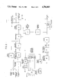
- FIG. 1 is a block circuit diagram of one form of speed control circuit for a vehicle
- FIG. 2 is a block circuit diagram of another form of speed control circuit for a vehicle which provides for multiple speed settings
- FIG. 3 is a block circuit diagram of a test unit for the speed control circuits of FIGS. 1 and 2, and
- FIG. 4 is a diagram of throttle control on a speed controlled vehicle.
- the circuit into which, in use, a pulse waveform generated by a Hall effect transducer 16 fitted to a gearbox of the vehicle is injected comprises a bandpass filter 1, frequency to voltage converter 2, voltage comparator 3, monostable 4, and power control 5.
- a potentiometer 6 provides a voltage reference source for one input of the voltage comparator and a fault monitoring circuit 7 is connected to the monostable 4 and power control 5 and through a "crowbar" switch 8 and fuse 9 to the positive terminal 10 of the battery 39 of the vehicle to which the circuit is connected.
- a fault indicator 11, which may be a light emitting diode or other appropriate element, is connected across the fuse 9.
- the battery is also connected through a filter 12 and 12/24 volt changeover switch 13 to a voltage regulator 14 which is operative to supply the various parts of the circuit with power supply at the appropriate voltage.
- a time circuit 15 is provided for controlling the application of an override signal to monostable 4.
- a further indicator 17, which may also be a light emitting diode or other appropriate element, is connected to the output of power control circuit 5. The output from circuit 5 is fed to a solenoid 40 which in turn controls operation of the vehicle throttle.
- the circuit of FIG. 2 is similar to the circuit of FIG. 1 (equivalent parts bear the same reference numerals). As compared with the arrangement of FIG. 1, however, provision is made for speed control at four separate speeds.
- a range selector 20 having four switches A, B, C and D, four display selector switches 21 to 24 corresponding respectively to switches A to D and driver logic 25 and a digital display are provided.
- the range selector 20 and display switches 21 to 24 are connected to a voltage reference source 27 which is operative to provide reference voltages corresponding to speeds selected by switches A, B, C and D. This source is connected through an analogue switch 28 to one input of comparator 3 as in the embodiment of FIG. 1.
- the test unit circuit comprises a frequency counter 32 which may be connected in operation through a changeover switch 31 to a frequency generator 30 or to the Hall effect transducer.
- the calibration input of counter 32 may also be connected through a further changeover switch 33 to a variable time oscillator 34 or a 1 MHz crystal controlled oscillator 35.
- the frequency counter is also connected to a 3 digit display 36.
- the unit power supply comprises a 120/240 volt voltage selector 37, a battery charger 38 and a nickel cadmium rechargeable battery 39.
- the solenoid controls the operation of the vehicle throttle by controlling flow of air from the vehicle air system to a hydraulic piston and cylinder device 41.
- This latter device operates a spring loaded piston 42 which is connected to the throttle. If the solenoid is actuated the throttle begins to close and vice versa.
- the setting up of the test unit and of the circuit of FIG. 1 will now be described.
- the vehicle to which the speed control circuit is fitted is driven at a low speed, conveniently on a rolling road, say 20 mph.
- the frequency of the pulse waveform (say 40 Hz) generated by the Hall effect transducer 16, which is proportional to the speed of the vehicle is measured by comparison with the output of oscillator 35 connected to the calibration input of frequency counter 32 as shown in FIG. 3.
- Switch 31 connects the output of transducer 16 to counter 32 for this purpose and is then switched over to connect generator 30 to the counter 32.
- a frequency count (shown on display 36) is then measured by counter 32 independently of transducer 16 by adjusting generator 30 which is the same as that generated by the transducer for the 20 mph speed, that is 40 Hz.
- Switch 33 is then switched over to disconnect oscillator 35 from and connect oscillator 34 to the calibration input of frequency counter 32.
- Oscillator 34 is then adjusted to give a calibration reading of 20 mph on display 36 while the generator 30 is generating the 40 Hz frequency.
- the unit is now calibrated to that particular vehicle.
- Such test signal at the selected speed frequency is injected into the speed control circuit through the test input socket referenced TI on FIG. 1.
- the voltage reference source 6 is adjusted for zero output from the voltage comparator which is indicated by the indicator switching between off and on. The circuit is then set.
- the waveform from the Hall effect transducer 16 is fed into the circuit via the transducer input socket TRI.
- Bandpass filter 1 eliminates unwanted frequencies so that illegal signals do not interfere with the operation of the system.
- the clear signal is passed through the frequency to voltage converter 2 producing a d.c. voltage proportional to the frequency and hence the vehicle speed.
- This d.c. voltage is compared with the reference voltage Vref such that when Vref is exceeded a signal is output from the comparator 3 to a monostable circuit 4.
- the purpose of the monostable is to provide a pulse long enough to operate an external solenoid. Thus if the comparator output is just a pulse, the solenoid will operate correctly. If the comparator output is continuous the monostable output will remain operated.
- the power control converts the monostable output to a sufficient power to operate the solenoid.
- L.E.D. indicator 17 illuminates when the solenoid is activated.
- the fault monitoring circuit 7 checks that the signal at the solenoid output is correct with the signal from the control circuit 5. If these are not compatable a serious operational fault could result causing vehicle failure.
- the fault monitoring circuit checks for this condition, and should it occur operates a crowbar circuit, rupturing the main supply fuse 9 and illuminating the fault L.E.D. 11. With no supply to the circuit, the vehicle reverts to normal operation. Each time the vehicle ignition is on the L.E.D. will give a permanent indication of fuse failure.
- test socket TS is provided to allow test and calibration using the test unit of FIG. 3.
- the ability to monitor and measure the incoming frequency allows calibration of road speed versus frequency. Also a frequency generated by speed and thus calibrate the unit whilst stationary for display on the test unit.
- the setting up and operation of the circuit of FIG. 2 is similar to that of the circuit of FIG. 1 for each of the speeds provided for.
- the speed at which the system operates is determined by the reference voltage fed to the comparator 3.
- this is provided by potentiometer 6.
- this is provided by one of four potentiometers selected by pushing the appropriate one of buttons A to D of range selector 20. These potentiometers are calibrated as described previously.
- Each display selector switch 21 to 24 comprises two rotary switches which may be adjusted to give a desired speed reading up to 99.
- Display 26 displays the speed currently selected.
- the override facility is incorporated to allow an immediate change to non-speed limited operation.
- When operated from an external switch timing circuit 15 is initiated which inhibits the solenoid signal for predetermined time.
- the digital speed display 26 (in the case of the circuit of FIG. 3) retains its current setting but flashes to signify the override condition. After the time period the system reverts to the condition prior to the override command.
Landscapes
- Engineering & Computer Science (AREA)
- Chemical & Material Sciences (AREA)
- Combustion & Propulsion (AREA)
- Transportation (AREA)
- Mechanical Engineering (AREA)
- Fluid Mechanics (AREA)
- Physics & Mathematics (AREA)
- Testing Or Calibration Of Command Recording Devices (AREA)
- Polarising Elements (AREA)
- Centrifugal Separators (AREA)
- Controls For Constant Speed Travelling (AREA)
- Control Of Ac Motors In General (AREA)
- Vending Machines For Individual Products (AREA)
- Control Of Electric Motors In General (AREA)
- Control Of Velocity Or Acceleration (AREA)
Applications Claiming Priority (2)
| Application Number | Priority Date | Filing Date | Title |
|---|---|---|---|
| GB858522274A GB8522274D0 (en) | 1985-09-07 | 1985-09-07 | Speed control unit |
| GB8522274 | 1985-09-07 |
Publications (1)
| Publication Number | Publication Date |
|---|---|
| US4786868A true US4786868A (en) | 1988-11-22 |
Family
ID=10584905
Family Applications (1)
| Application Number | Title | Priority Date | Filing Date |
|---|---|---|---|
| US06/904,120 Expired - Fee Related US4786868A (en) | 1985-09-07 | 1986-09-05 | Speed control unit |
Country Status (5)
| Country | Link |
|---|---|
| US (1) | US4786868A (de) |
| EP (1) | EP0214849B1 (de) |
| AT (1) | ATE70231T1 (de) |
| DE (1) | DE3682849D1 (de) |
| GB (1) | GB8522274D0 (de) |
Cited By (2)
| Publication number | Priority date | Publication date | Assignee | Title |
|---|---|---|---|---|
| US5844411A (en) * | 1995-05-31 | 1998-12-01 | Borg-Warner Automotive, Inc. | Diagnostic detection for hall effect digital gear tooth sensors and related method |
| WO2000005092A1 (en) * | 1998-07-20 | 2000-02-03 | Marco Magliocchetti | Programmable speed limit device for passenger cars, trucks and motorcycles |
Families Citing this family (2)
| Publication number | Priority date | Publication date | Assignee | Title |
|---|---|---|---|---|
| GB9111544D0 (en) * | 1991-05-29 | 1991-07-17 | Romatic Ltd | A speed control unit |
| DE4435705A1 (de) * | 1994-10-06 | 1996-04-11 | Manfred Roessle | Verfahren und Einrichtung zur Begrenzung der Geschwindigkeit eines Kraftfahrzeuges |
Citations (6)
| Publication number | Priority date | Publication date | Assignee | Title |
|---|---|---|---|---|
| US3340951A (en) * | 1964-04-24 | 1967-09-12 | Gen Electric | Speed control system |
| DE2501297A1 (de) * | 1974-01-17 | 1975-07-24 | Ass Eng Ltd | Systeme, die auf eine geschwindigkeit anprechen und betaetigervorrichtung |
| US4166977A (en) * | 1976-09-16 | 1979-09-04 | Robert Bosch Gmbh | Rotary speed and angular position determination system, particularly for the crankshaft of an internal combustion engine |
| US4366373A (en) * | 1980-10-14 | 1982-12-28 | Electro Corporation | Event rate counter |
| US4570110A (en) * | 1984-08-29 | 1986-02-11 | International Business Machines Corporation | Programmable servo motor speed control apparatus |
| US4597465A (en) * | 1982-10-27 | 1986-07-01 | A.R.A. Manufacturing Company | Cruise control system and method with overspeed sensor |
Family Cites Families (5)
| Publication number | Priority date | Publication date | Assignee | Title |
|---|---|---|---|---|
| CH412417A (de) * | 1965-11-18 | 1966-04-30 | Scheu Jakob | Steuervorrichtung zur Begrenzung von Fahrzeug-Geschwindigkeiten |
| US3587769A (en) * | 1969-02-17 | 1971-06-28 | John G Lotter | Vehicle speed control system |
| FR2318756A1 (fr) * | 1975-07-23 | 1977-02-18 | Citroen Sa | Dispositifs limiteurs de vitesse pour vehicules automobiles |
| US4352403A (en) * | 1979-03-22 | 1982-10-05 | Travel Accessories Manufacturing Co., Inc. | Vehicle speed control system |
| DE3237535A1 (de) * | 1982-10-09 | 1984-04-12 | Vdo Adolf Schindling Ag, 6000 Frankfurt | Einrichtung zum steuern der fahrgeschwindigkeit eines kraftfahrzeuges |
-
1985
- 1985-09-07 GB GB858522274A patent/GB8522274D0/en active Pending
-
1986
- 1986-09-05 EP EP86306866A patent/EP0214849B1/de not_active Expired - Lifetime
- 1986-09-05 DE DE8686306866T patent/DE3682849D1/de not_active Expired - Fee Related
- 1986-09-05 US US06/904,120 patent/US4786868A/en not_active Expired - Fee Related
- 1986-09-05 AT AT86306866T patent/ATE70231T1/de not_active IP Right Cessation
Patent Citations (6)
| Publication number | Priority date | Publication date | Assignee | Title |
|---|---|---|---|---|
| US3340951A (en) * | 1964-04-24 | 1967-09-12 | Gen Electric | Speed control system |
| DE2501297A1 (de) * | 1974-01-17 | 1975-07-24 | Ass Eng Ltd | Systeme, die auf eine geschwindigkeit anprechen und betaetigervorrichtung |
| US4166977A (en) * | 1976-09-16 | 1979-09-04 | Robert Bosch Gmbh | Rotary speed and angular position determination system, particularly for the crankshaft of an internal combustion engine |
| US4366373A (en) * | 1980-10-14 | 1982-12-28 | Electro Corporation | Event rate counter |
| US4597465A (en) * | 1982-10-27 | 1986-07-01 | A.R.A. Manufacturing Company | Cruise control system and method with overspeed sensor |
| US4570110A (en) * | 1984-08-29 | 1986-02-11 | International Business Machines Corporation | Programmable servo motor speed control apparatus |
Cited By (2)
| Publication number | Priority date | Publication date | Assignee | Title |
|---|---|---|---|---|
| US5844411A (en) * | 1995-05-31 | 1998-12-01 | Borg-Warner Automotive, Inc. | Diagnostic detection for hall effect digital gear tooth sensors and related method |
| WO2000005092A1 (en) * | 1998-07-20 | 2000-02-03 | Marco Magliocchetti | Programmable speed limit device for passenger cars, trucks and motorcycles |
Also Published As
| Publication number | Publication date |
|---|---|
| ATE70231T1 (de) | 1991-12-15 |
| DE3682849D1 (de) | 1992-01-23 |
| EP0214849A3 (en) | 1988-07-13 |
| EP0214849A2 (de) | 1987-03-18 |
| EP0214849B1 (de) | 1991-12-11 |
| GB8522274D0 (en) | 1985-10-16 |
Similar Documents
| Publication | Publication Date | Title |
|---|---|---|
| US4419654A (en) | Tractor data center | |
| CA1216671A (en) | Vehicle brake test apparatus | |
| CA1115844A (en) | Apparatus for controlling an odometer and speedometer system of a vehicle | |
| EP0028625B1 (de) | Zweiseitig gerichtetes integriergerät | |
| US4760736A (en) | On board indicator for motor vehicles | |
| US4786868A (en) | Speed control unit | |
| EP0092486B1 (de) | Anzeigevorrichtung für Geschwindigkeitsmesser für Kraftfahrzeug | |
| AU725600B2 (en) | Method and apparatus to determine the location and resistance of an electrical leak within a battery without measuring individual battery cells | |
| US3781656A (en) | Stroboscope with visual speed indicating system employing lights | |
| EP0438537B1 (de) | Vorrichtung zur überwachung und anzeige einer bestimmten mindest-energiereserve von batterien | |
| DE3531560C2 (de) | ||
| US4291268A (en) | Apparatus for driving a deflecting coil type meter | |
| CA1328491C (en) | Pulse generation and tracking system | |
| US5027640A (en) | Speedometer/odometer/cruise control tester and related methods | |
| JPS5799413A (en) | Automatic air conditioner | |
| US4007642A (en) | System and method for identifying angular location and amount of wheel balancing weights | |
| DE19755586A1 (de) | Kraftfahrzeug Kombigerät | |
| US5097203A (en) | Method and circuit for producing an input variable for a cross-coil indicating device | |
| US4087783A (en) | Wheel interference monitor | |
| GB2273365A (en) | Hand-held digital multimeter capable of performing isolation resistance measurements | |
| US4661772A (en) | Measuring and testing circuit | |
| EP1745263B1 (de) | Anzeigevorrichtung | |
| CN221056059U (zh) | 一种eps硬件故障注入设备 | |
| RU2258936C1 (ru) | Цветовой индикатор помех бортовой сети автомобиля | |
| GB2087080A (en) | Fuel consumption measurement system for internal combustion engines |
Legal Events
| Date | Code | Title | Description |
|---|---|---|---|
| AS | Assignment |
Owner name: ROMATIC LIMITED, UNIT 3, DERWENT STREET, TRADING E Free format text: ASSIGNMENT OF ASSIGNORS INTEREST.;ASSIGNOR:NIELD, ERIC L.;REEL/FRAME:004650/0092 Effective date: 19861117 Owner name: ROMATIC LIMITED, ENGLAND Free format text: ASSIGNMENT OF ASSIGNORS INTEREST;ASSIGNOR:NIELD, ERIC L.;REEL/FRAME:004650/0092 Effective date: 19861117 |
|
| FEPP | Fee payment procedure |
Free format text: PAYOR NUMBER ASSIGNED (ORIGINAL EVENT CODE: ASPN); ENTITY STATUS OF PATENT OWNER: SMALL ENTITY |
|
| REMI | Maintenance fee reminder mailed | ||
| FPAY | Fee payment |
Year of fee payment: 4 |
|
| SULP | Surcharge for late payment | ||
| REMI | Maintenance fee reminder mailed | ||
| LAPS | Lapse for failure to pay maintenance fees | ||
| FP | Lapsed due to failure to pay maintenance fee |
Effective date: 19961127 |
|
| STCH | Information on status: patent discontinuation |
Free format text: PATENT EXPIRED DUE TO NONPAYMENT OF MAINTENANCE FEES UNDER 37 CFR 1.362 |