US4787491A - Selecting device of a power transmission system for a four-wheel drive vehicle - Google Patents
Selecting device of a power transmission system for a four-wheel drive vehicle Download PDFInfo
- Publication number
- US4787491A US4787491A US07/035,639 US3563987A US4787491A US 4787491 A US4787491 A US 4787491A US 3563987 A US3563987 A US 3563987A US 4787491 A US4787491 A US 4787491A
- Authority
- US
- United States
- Prior art keywords
- reverse
- overrunning clutch
- teeth
- shaft
- toothing
- Prior art date
- Legal status (The legal status is an assumption and is not a legal conclusion. Google has not performed a legal analysis and makes no representation as to the accuracy of the status listed.)
- Expired - Fee Related
Links
Images


Classifications
-
- F—MECHANICAL ENGINEERING; LIGHTING; HEATING; WEAPONS; BLASTING
- F16—ENGINEERING ELEMENTS AND UNITS; GENERAL MEASURES FOR PRODUCING AND MAINTAINING EFFECTIVE FUNCTIONING OF MACHINES OR INSTALLATIONS; THERMAL INSULATION IN GENERAL
- F16D—COUPLINGS FOR TRANSMITTING ROTATION; CLUTCHES; BRAKES
- F16D41/00—Freewheels or freewheel clutches
- F16D41/06—Freewheels or freewheel clutches with intermediate wedging coupling members between an inner and an outer surface
- F16D41/08—Freewheels or freewheel clutches with intermediate wedging coupling members between an inner and an outer surface with provision for altering the freewheeling action
-
- B—PERFORMING OPERATIONS; TRANSPORTING
- B60—VEHICLES IN GENERAL
- B60K—ARRANGEMENT OR MOUNTING OF PROPULSION UNITS OR OF TRANSMISSIONS IN VEHICLES; ARRANGEMENT OR MOUNTING OF PLURAL DIVERSE PRIME-MOVERS IN VEHICLES; AUXILIARY DRIVES FOR VEHICLES; INSTRUMENTATION OR DASHBOARDS FOR VEHICLES; ARRANGEMENTS IN CONNECTION WITH COOLING, AIR INTAKE, GAS EXHAUST OR FUEL SUPPLY OF PROPULSION UNITS IN VEHICLES
- B60K17/00—Arrangement or mounting of transmissions in vehicles
- B60K17/34—Arrangement or mounting of transmissions in vehicles for driving both front and rear wheels, e.g. four wheel drive vehicles
- B60K17/348—Arrangement or mounting of transmissions in vehicles for driving both front and rear wheels, e.g. four wheel drive vehicles having differential means for driving one set of wheels, e.g. the front, at one speed and the other set, e.g. the rear, at a different speed
- B60K17/35—Arrangement or mounting of transmissions in vehicles for driving both front and rear wheels, e.g. four wheel drive vehicles having differential means for driving one set of wheels, e.g. the front, at one speed and the other set, e.g. the rear, at a different speed including arrangements for suppressing or influencing the power transfer, e.g. viscous clutches
- B60K17/3505—Arrangement or mounting of transmissions in vehicles for driving both front and rear wheels, e.g. four wheel drive vehicles having differential means for driving one set of wheels, e.g. the front, at one speed and the other set, e.g. the rear, at a different speed including arrangements for suppressing or influencing the power transfer, e.g. viscous clutches with self-actuated means, e.g. by difference of speed
-
- F—MECHANICAL ENGINEERING; LIGHTING; HEATING; WEAPONS; BLASTING
- F16—ENGINEERING ELEMENTS AND UNITS; GENERAL MEASURES FOR PRODUCING AND MAINTAINING EFFECTIVE FUNCTIONING OF MACHINES OR INSTALLATIONS; THERMAL INSULATION IN GENERAL
- F16D—COUPLINGS FOR TRANSMITTING ROTATION; CLUTCHES; BRAKES
- F16D47/00—Systems of clutches, or clutches and couplings, comprising devices of types grouped under at least two of the following sets of groups: F16D1/00 - F16D9/00, F16D11/00 - F16D23/00, F16D25/00 - F16D29/00, F16D31/00 - F16D39/00, F16D41/00 - F16D45/00
- F16D47/04—Systems of clutches, or clutches and couplings, comprising devices of types grouped under at least two of the following sets of groups: F16D1/00 - F16D9/00, F16D11/00 - F16D23/00, F16D25/00 - F16D29/00, F16D31/00 - F16D39/00, F16D41/00 - F16D45/00 of which at least one is a freewheel
Definitions
- the present invention relates to a power transmission system for a full-time four-wheel drive vehicle having a mechanism for absorbing the difference between the speeds of the front and rear wheels.
- the overrunning clutch system comprises forward and reverse overrunning clutches each in the form of a freewheel and a sleeve for selecting forward driving mode, reverse driving mode or a directly connected four-wheel driving mode for the locking of the system. These modes can be selected by engaging toothings of the sleeve with toothings of one of the clutches or with toothings of both clutches.
- a chamfer of the selected clutch possibly abuts an improper side of the chamfer of the sleeve. Namely, when one of the chamfers of the sleeve abuts against one of the chamfers of the clutch, the clutch is forced to rotate in one direction. If the direction is the locking direction of the clutch, the clutch cannot rotate. Thus, the sleeve also stops shifting.
- the object of the present invention is to provide a power transmission system for a full-time four-wheel drive vehicle which prevents the tight corner braking at corners by providing a double overrunning clutch system, wherein forward and reverse driving modes are smoothly and quickly selected.
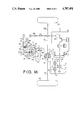
- FIGS. 1a and 1b show a schematic illustration showing a power transmission system according to the present invention
- FIG. 2 is a sectional view of a main portion of the system
- FIG. 3 is an enlarged sectional view showing a part of FIG. 2;
- FIG. 4a is a sectional view taken along a line IV--IV of FIG. 3;
- FIG. 4b is a sectional view of toothings, explaining the engaging operation.
- an engine unit E is transversely mounted on a rear portion of a vehicle.
- the engine unit has an engine 1, clutch 2 and transmission 3.
- the output of the transmission 3 is transmitted to rear wheels 23 through a differential 4 and axles 22.
- the output of the transmission 3 is also transmitted to front wheels 10 through a front wheel driving power transmission system comprising a transfer device 5, double overrunning clutch 6, propeller shaft 7, differential 8, and axles 9.
- a case 13 of the clutch 6 is secured to a case 11 of the transmission 3 through an intermediate case 12.
- the transmission 3 comprises an input shaft 15, output shaft 16, a plurality of change-speed gears 17, and synchronizers 18.
- An output gear 19 engages with a ring gear 20 secured to a case 21 of the differential 4.
- the transfer device 5 comprises a gear 24 engaged with ring gear 20, bevel gear 26 on a shaft 25 of gear 24, and bevel gear 27 engaged with bevel gear 26.
- a transfer drive shaft 28 of the bevel gear 27 and a driven shaft 29 connected to the propeller shaft 7 are co-axially disposed, and both shafts 28 and 29 are coupled through double overrunning clutch 6.
- the double overrunning clutch 6 comprises a forward overrunning clutch 30 and reverse overrunning clutch 31 each of which is in the form of a freewheel.
- Clutches 30 and 31 comprise outer races 30a, 31a and spragges 30c, 31c disposed between the outer races 30a, 31a and shaft 29, respectively. Spragges are able to rotate on the shaft 29 in one direction.
- a forward/reverse selecting device 32 is provided. The device has a hub 33 secured to the shaft 28 and an axially slidable sleeve 34.
- the sleeve 34 has two inside toothings 34a and 34b.
- the toothing 34a is permanently engaged with a toothing 33a of the hub 33.
- the toothing 34b is selectively engaged with a toothing 30b of the forward overrunning clutch 30 or with a toothing 31b of the reverse overrunning clutch 31.
- the toothing 34b has such a width that it engages with both toothings 30b and 31b at the same time. Such a selection is performed by shifting the sleeve 34 to one of three axial positions, namely, a forward position, reverse position and lock position.
- the forward overrunning clutch 30 is so arranged as to transmit the rotation of the outer race 30a in the forward driving direction to the shaft 29 and as to allow the rotation of the shaft 29 in this direction at higher speed than the outer race, i.e. in advance of the race.
- the reverse overrunning clutch 31 is arranged oppositely. As shown in FIG. 4a, each of the toothings 30b and 31b of the clutches 30 and 31 is chamfered at an end opposing the toothing 34b. A chamfer 30d of the toothing 30b is formed at an angle ⁇ toward a freely rotatable direction F1 of the outer race 30a.
- a chamfer 31d of the toothing 31b is also formed at the angle ⁇ toward a freely rotatable direction F2 of the outer race 31a, which is opposite to the rotatable direction F1 of the outer race 30a.
- the toothing 34b has chamfers 34c and 34d at both ends at angle ⁇ so that the chamfer 34c and 34d may engage with the chamfers 30d and 31d, respectively.
- the sleeve 34 has an annular groove on the periphery thereof, in which a shifter fork 38 is slidably engaged.
- the shifter fork 38 is operatively connected to a diaphragm 36 (FIG. 1) in a vacuum operated actuator 35 through a rod 37.
- a ball lock device 47 is provided to position the rod 37 at one of the three positions.
- the diaphragm 36 of the actuator 35 is held by springs 40 and 41 on both sides thereof to an intermediate lock position when both vacuum chambers 39a and 39b defined by the diaphragm are communicated with the atmosphere as described hereinafter.
- the vacuum chambers 39a and 39b are communicated with ports 61a and 62a of solenoid operated valves 61 and 62, respectively (FIG. 1b).
- the solenoid operated valve 61 and 62 have atmosphere ports 61b and 62b, vacuum ports 61c and 62c, and solenoids 61d and 62d respectively.
- Both vacuum ports 61c and 62c are communicated with an intake manifold 65 of the engine 1 through a passage 44 having a check valve 45 so as to be supplied with vacuum pressure in the intake manifold 65.
- Each valve has a valve body 66 for selectively closing the atmosphere port or vacuum port in accordance with energization or deenergization of the solenoid.
- the solenoid When the solenoid is energized by the output of a control circuit 46, the valve body 66 closes the atmosphere port and opens the vacuum port to communicate the vacuum chamber of the actuator 35 with the intake manifold 65.
- the control circuit 46 is provided with a reverse switch 50 which is closed when a reverse gear in the transmission 3 is selected, and a lock switch 51 for locking the overrunning clutches 30 and 31.
- the chamfer 34c abuts against the chamfer 30d to produce a component on the toothing 30b in the free direction F1. Accordingly, the outer race 30a is rotated in the free direction, so that the toothing 34b can smoothly move to the left as shown in FIG. 4a. Thus, the engagement of the sleeve 34 and the clutch 30 is smoothly performed.
- the output of the change-speed transmission 3 is transmitted to the front wheels 10 through shaft 28, forward overrunning clutch 30, shaft 29 and propeller shaft 7.
- the front wheels 10 rotate faster than the rear wheels 23. That is, the shaft 29 rotates faster than the outer race 30a in advance of it.
- the overrunning clutch 30 permits such a faster rotation of the shaft 29.
- the difference between the speeds of the front and rear wheels is absorbed in the clutch, and the vehicle turns the corner smoothly without braking phenomenon.
- the reverse switch 50 When the transmission 3 is changed to reverse driving state, the reverse switch 50 is closed. Accordingly, the solenoid 62d is energized so that vacuum chamber 39b is communicated with the intake manifold 65, shifting the rod 37 to the right (reverse position).
- the reverse overrunning clutch 31 is selected in the same manner as described above but for the reverse driving. In reverse driving, the same operation as the forward driving is performed but in reverse.
- the solenoids 61d, 62d are de-energized to communicate vacuum chambers 39a, 39b with the atmosphere.
- the diaphragm 36 is located at the neutral position by springs 40, 41 to position the rod 37 at the lock position. Accordingly, the toothing 34b of the sleeve 34 engages with both toothings 30b and 31b to lock the double overrunning clutch 6.
- the directly connected four-wheel driving mode is established. Therefore, the vehicle is safely driven by four the wheels without skidding of wheels.
Landscapes
- Engineering & Computer Science (AREA)
- General Engineering & Computer Science (AREA)
- Mechanical Engineering (AREA)
- Chemical & Material Sciences (AREA)
- Combustion & Propulsion (AREA)
- Transportation (AREA)
- Arrangement And Driving Of Transmission Devices (AREA)
- Arrangement And Mounting Of Devices That Control Transmission Of Motive Force (AREA)
Applications Claiming Priority (2)
| Application Number | Priority Date | Filing Date | Title |
|---|---|---|---|
| JP61080685A JPS62238115A (ja) | 1986-04-07 | 1986-04-07 | 4輪駆動車の駆動軸選択装置 |
| JP61-080685 | 1986-04-07 |
Publications (1)
| Publication Number | Publication Date |
|---|---|
| US4787491A true US4787491A (en) | 1988-11-29 |
Family
ID=13725193
Family Applications (1)
| Application Number | Title | Priority Date | Filing Date |
|---|---|---|---|
| US07/035,639 Expired - Fee Related US4787491A (en) | 1986-04-07 | 1987-04-03 | Selecting device of a power transmission system for a four-wheel drive vehicle |
Country Status (5)
| Country | Link |
|---|---|
| US (1) | US4787491A (de) |
| EP (1) | EP0242094B1 (de) |
| JP (1) | JPS62238115A (de) |
| AT (1) | ATE55949T1 (de) |
| DE (1) | DE3764516D1 (de) |
Cited By (17)
| Publication number | Priority date | Publication date | Assignee | Title |
|---|---|---|---|---|
| US5044479A (en) * | 1990-03-12 | 1991-09-03 | Boulder 12 Investments | Remote-activated, power shift clutch assembly |
| US5123513A (en) * | 1990-03-12 | 1992-06-23 | Boulder 12 Investments | Remote-activated, power shift clutch assembly with positive locking |
| US5542514A (en) * | 1993-06-10 | 1996-08-06 | Ntn Corporation | Rotational transmission device |
| US5937980A (en) * | 1997-02-24 | 1999-08-17 | Dana Corporation | Bi-directional one-way clutch |
| US5971123A (en) * | 1998-10-09 | 1999-10-26 | Hilliard Corporation | Bi-directional overrunning clutch |
| US6165103A (en) * | 1999-05-07 | 2000-12-26 | Visteon Global Technologies, Inc. | Shifting mechanism |
| US6193629B1 (en) * | 1999-05-07 | 2001-02-27 | Ford Global Technologies, Inc. | Shifting mechanism |
| EP1253041A3 (de) * | 2001-04-27 | 2003-08-13 | New Venture Gear, Inc. | Bedarfsabhängiges Vierradantriebsverteilergetriebe mit steuerbarer Zweirichtungskupplungsanordnung |
| US6622837B2 (en) | 2000-11-17 | 2003-09-23 | The Hilliard Corporation | Bi-directional overrunning clutch with automatic backdrive |
| US6691847B2 (en) * | 1998-11-26 | 2004-02-17 | Ker-Train Holdings Ltd. | Power transfer device |
| US6739440B1 (en) | 2003-06-06 | 2004-05-25 | Torque-Traction Technologies, Inc. | Bi-directional one-way clutch |
| US20060254382A1 (en) * | 2005-04-12 | 2006-11-16 | Tomoyuki Ebihara | Bi-directional clutch and vehicle with it |
| US20070034471A1 (en) * | 2005-08-09 | 2007-02-15 | Nissan Motor Co., Ltd. | Drive force transmission device |
| US20070175724A1 (en) * | 2006-01-27 | 2007-08-02 | Rubino Marcos T | Automatically releaseable bidirectional overrunning clutch |
| US20070286743A1 (en) * | 2006-06-08 | 2007-12-13 | Hilliard Corporation | Self-energizing pump for overrunning clutch |
| US9784355B1 (en) | 2016-08-31 | 2017-10-10 | Dana Heavy Vehicle Systems Group, Llc | Axle disconnect and differential lock combination |
| US20220314998A1 (en) * | 2019-06-27 | 2022-10-06 | Jukka AUVINEN | A braking control arrangement for a braking system of a vehicle |
Families Citing this family (2)
| Publication number | Priority date | Publication date | Assignee | Title |
|---|---|---|---|---|
| DE4038363A1 (de) * | 1990-12-01 | 1992-08-27 | Walterscheid Gmbh Jean | Antriebsanordnung fuer vierradgetriebene gelaendefahrzeuge, insbesondere traktoren |
| ATE268876T1 (de) * | 1997-07-15 | 2004-06-15 | Engelbert Gmeilbauer | Freilauf-ratscheneinrichtung |
Citations (8)
| Publication number | Priority date | Publication date | Assignee | Title |
|---|---|---|---|---|
| US2635478A (en) * | 1947-10-15 | 1953-04-21 | Chrysler Corp | Power transmission |
| US2667251A (en) * | 1938-08-15 | 1954-01-26 | New Prod Corp | Clutch shifting means for transmissions |
| US2850920A (en) * | 1950-12-21 | 1958-09-09 | Rockwell Spring & Axle Co | Vehicle drive mechanism |
| US2853890A (en) * | 1951-09-18 | 1958-09-30 | Borg Warner | Transmission |
| US3651907A (en) * | 1970-08-03 | 1972-03-28 | Boise Cascade Corp | Overrunning clutch for transfer case transmission |
| JPS554292A (en) * | 1978-06-23 | 1980-01-12 | Fuji Heavy Ind Ltd | Speed changer for automobile |
| JPS5643035A (en) * | 1979-09-13 | 1981-04-21 | Fuji Heavy Ind Ltd | Four wheel drive with automatic transmission |
| JPS5715019A (en) * | 1980-06-27 | 1982-01-26 | Fuji Heavy Ind Ltd | Changeover device for 2, 4 wheel drive in 4-wheel drive vehicle |
Family Cites Families (4)
| Publication number | Priority date | Publication date | Assignee | Title |
|---|---|---|---|---|
| US4083419A (en) * | 1976-08-23 | 1978-04-11 | Borg-Warner Corporation | Automatic four-wheel drive transfer case |
| JPS60154628U (ja) * | 1984-03-23 | 1985-10-15 | 株式会社 大金製作所 | 産業機械用車輌等の動力切換装置 |
| GB2163107A (en) * | 1984-08-15 | 1986-02-19 | Fuji Heavy Ind Ltd | Four-wheel drive vehicle transmission |
| DE3508663A1 (de) * | 1985-03-12 | 1986-09-25 | Thyssen Industrie Ag, 4300 Essen | Kraftfahrzeug mit allradantrieb |
-
1986
- 1986-04-07 JP JP61080685A patent/JPS62238115A/ja active Pending
-
1987
- 1987-04-03 US US07/035,639 patent/US4787491A/en not_active Expired - Fee Related
- 1987-04-03 AT AT87302931T patent/ATE55949T1/de not_active IP Right Cessation
- 1987-04-03 DE DE8787302931T patent/DE3764516D1/de not_active Expired - Lifetime
- 1987-04-03 EP EP87302931A patent/EP0242094B1/de not_active Expired - Lifetime
Patent Citations (8)
| Publication number | Priority date | Publication date | Assignee | Title |
|---|---|---|---|---|
| US2667251A (en) * | 1938-08-15 | 1954-01-26 | New Prod Corp | Clutch shifting means for transmissions |
| US2635478A (en) * | 1947-10-15 | 1953-04-21 | Chrysler Corp | Power transmission |
| US2850920A (en) * | 1950-12-21 | 1958-09-09 | Rockwell Spring & Axle Co | Vehicle drive mechanism |
| US2853890A (en) * | 1951-09-18 | 1958-09-30 | Borg Warner | Transmission |
| US3651907A (en) * | 1970-08-03 | 1972-03-28 | Boise Cascade Corp | Overrunning clutch for transfer case transmission |
| JPS554292A (en) * | 1978-06-23 | 1980-01-12 | Fuji Heavy Ind Ltd | Speed changer for automobile |
| JPS5643035A (en) * | 1979-09-13 | 1981-04-21 | Fuji Heavy Ind Ltd | Four wheel drive with automatic transmission |
| JPS5715019A (en) * | 1980-06-27 | 1982-01-26 | Fuji Heavy Ind Ltd | Changeover device for 2, 4 wheel drive in 4-wheel drive vehicle |
Cited By (24)
| Publication number | Priority date | Publication date | Assignee | Title |
|---|---|---|---|---|
| US5044479A (en) * | 1990-03-12 | 1991-09-03 | Boulder 12 Investments | Remote-activated, power shift clutch assembly |
| US5123513A (en) * | 1990-03-12 | 1992-06-23 | Boulder 12 Investments | Remote-activated, power shift clutch assembly with positive locking |
| US5542514A (en) * | 1993-06-10 | 1996-08-06 | Ntn Corporation | Rotational transmission device |
| US5937980A (en) * | 1997-02-24 | 1999-08-17 | Dana Corporation | Bi-directional one-way clutch |
| US5971123A (en) * | 1998-10-09 | 1999-10-26 | Hilliard Corporation | Bi-directional overrunning clutch |
| USRE38012E1 (en) | 1998-10-09 | 2003-03-04 | Hilliard Corporation | Bi-directional overrunning clutch |
| US6691847B2 (en) * | 1998-11-26 | 2004-02-17 | Ker-Train Holdings Ltd. | Power transfer device |
| US6165103A (en) * | 1999-05-07 | 2000-12-26 | Visteon Global Technologies, Inc. | Shifting mechanism |
| US6193629B1 (en) * | 1999-05-07 | 2001-02-27 | Ford Global Technologies, Inc. | Shifting mechanism |
| US6286379B1 (en) * | 1999-05-07 | 2001-09-11 | Ford Global Technologies, Inc. | Method for shifting multi-speed axles |
| US6622837B2 (en) | 2000-11-17 | 2003-09-23 | The Hilliard Corporation | Bi-directional overrunning clutch with automatic backdrive |
| EP1253041A3 (de) * | 2001-04-27 | 2003-08-13 | New Venture Gear, Inc. | Bedarfsabhängiges Vierradantriebsverteilergetriebe mit steuerbarer Zweirichtungskupplungsanordnung |
| US6739440B1 (en) | 2003-06-06 | 2004-05-25 | Torque-Traction Technologies, Inc. | Bi-directional one-way clutch |
| US20060254382A1 (en) * | 2005-04-12 | 2006-11-16 | Tomoyuki Ebihara | Bi-directional clutch and vehicle with it |
| US7588112B2 (en) * | 2005-04-12 | 2009-09-15 | Kanzaki Kokyukoki Mfg. Co., Ltd. | Bi-directional clutch and vehicle with it |
| US20070034471A1 (en) * | 2005-08-09 | 2007-02-15 | Nissan Motor Co., Ltd. | Drive force transmission device |
| US7581626B2 (en) * | 2005-08-09 | 2009-09-01 | Nissan Motor Co., Ltd. | Drive force transmission device |
| US20070175724A1 (en) * | 2006-01-27 | 2007-08-02 | Rubino Marcos T | Automatically releaseable bidirectional overrunning clutch |
| US7389863B2 (en) * | 2006-01-27 | 2008-06-24 | Warner Electric Technology, Llc | Automatically releaseable bidirectional overrunning clutch |
| US20070286743A1 (en) * | 2006-06-08 | 2007-12-13 | Hilliard Corporation | Self-energizing pump for overrunning clutch |
| US7410042B2 (en) | 2006-06-08 | 2008-08-12 | The Hilliard Corporation | Self-energizing pump for overrunning clutch |
| US9784355B1 (en) | 2016-08-31 | 2017-10-10 | Dana Heavy Vehicle Systems Group, Llc | Axle disconnect and differential lock combination |
| US20220314998A1 (en) * | 2019-06-27 | 2022-10-06 | Jukka AUVINEN | A braking control arrangement for a braking system of a vehicle |
| US12134383B2 (en) * | 2019-06-27 | 2024-11-05 | Jukka AUVINEN | Braking control arrangement for a braking system of a vehicle |
Also Published As
| Publication number | Publication date |
|---|---|
| EP0242094A2 (de) | 1987-10-21 |
| DE3764516D1 (de) | 1990-10-04 |
| EP0242094A3 (en) | 1988-02-03 |
| EP0242094B1 (de) | 1990-08-29 |
| JPS62238115A (ja) | 1987-10-19 |
| ATE55949T1 (de) | 1990-09-15 |
Similar Documents
| Publication | Publication Date | Title |
|---|---|---|
| US4787491A (en) | Selecting device of a power transmission system for a four-wheel drive vehicle | |
| US6846262B2 (en) | Transfer case shift system for controllable bi-directional overrunning clutch | |
| US5098360A (en) | Differential gear with limited slip and locking mechanism | |
| US9784355B1 (en) | Axle disconnect and differential lock combination | |
| US4559846A (en) | System for shifting a vehicle to two or four-wheel drive | |
| JP5675628B2 (ja) | 複数の列のラチェット要素を有するワンウェイまたは選択可能クラッチ | |
| US6588559B2 (en) | Two-way clutch biasing assembly | |
| US6620073B2 (en) | Driving force transmitting device for vehicle | |
| KR19990077679A (ko) | 변속기 케이스와 그 밖의 유사한것을 위한 양-방향 오버런닝 클러치 조립체 | |
| US6520305B2 (en) | Clutch collar | |
| US6557680B2 (en) | On-demand transfer case with integrated sprocket and bi-directional clutch assembly | |
| US4805718A (en) | Power transmission system for a four-wheel drive | |
| US6755090B2 (en) | Retaining mechanism for transmission gears | |
| US20050197228A1 (en) | Variable biasing differential | |
| US5036940A (en) | Transfer differential gear lock controller | |
| GB2163107A (en) | Four-wheel drive vehicle transmission | |
| US6432021B1 (en) | Three mode differential | |
| US5862900A (en) | Transmission synchronizer mechanism | |
| US5462148A (en) | Vehicle multi-ratio transmission | |
| US6413184B1 (en) | Power transmission system for four-wheel drive vehicle | |
| US20090250309A1 (en) | Hydraulic Shift System for Power Transfer Devices | |
| JPS6323047A (ja) | 一体型多機能差動装置 | |
| JP4246301B2 (ja) | 車両用4輪駆動装置 | |
| KR0146461B1 (ko) | 연속자동 변속장치 | |
| JPS63227421A (ja) | 4輪駆動車 |
Legal Events
| Date | Code | Title | Description |
|---|---|---|---|
| AS | Assignment |
Owner name: FUJI JUKOGYO KABUSHIKI KAISHA, 7-2 NISHISHINJUKU 1 Free format text: ASSIGNMENT OF ASSIGNORS INTEREST.;ASSIGNOR:KATO, SHOJI;REEL/FRAME:004690/0508 Effective date: 19870320 |
|
| REMI | Maintenance fee reminder mailed | ||
| LAPS | Lapse for failure to pay maintenance fees | ||
| FP | Lapsed due to failure to pay maintenance fee |
Effective date: 19921129 |
|
| STCH | Information on status: patent discontinuation |
Free format text: PATENT EXPIRED DUE TO NONPAYMENT OF MAINTENANCE FEES UNDER 37 CFR 1.362 |