US4797000A - Comparative colorimeter - Google Patents
Comparative colorimeter Download PDFInfo
- Publication number
- US4797000A US4797000A US06/815,522 US81552286A US4797000A US 4797000 A US4797000 A US 4797000A US 81552286 A US81552286 A US 81552286A US 4797000 A US4797000 A US 4797000A
- Authority
- US
- United States
- Prior art keywords
- photodetector
- sample
- tube
- light
- sample tube
- Prior art date
- Legal status (The legal status is an assumption and is not a legal conclusion. Google has not performed a legal analysis and makes no representation as to the accuracy of the status listed.)
- Expired - Lifetime
Links
- 230000000052 comparative effect Effects 0.000 title abstract description 18
- 230000003287 optical effect Effects 0.000 claims abstract description 66
- 230000000694 effects Effects 0.000 claims abstract description 13
- 239000007788 liquid Substances 0.000 claims abstract description 9
- 230000007547 defect Effects 0.000 claims description 18
- 230000001419 dependent effect Effects 0.000 claims description 7
- 238000012935 Averaging Methods 0.000 claims description 4
- 239000000523 sample Substances 0.000 abstract description 86
- 238000012937 correction Methods 0.000 abstract description 19
- 239000012488 sample solution Substances 0.000 abstract description 13
- 239000012086 standard solution Substances 0.000 abstract description 10
- 238000006243 chemical reaction Methods 0.000 abstract description 8
- 238000013461 design Methods 0.000 description 35
- 239000000243 solution Substances 0.000 description 13
- 238000002835 absorbance Methods 0.000 description 12
- 239000011521 glass Substances 0.000 description 12
- 238000012360 testing method Methods 0.000 description 10
- 239000003990 capacitor Substances 0.000 description 7
- 238000005259 measurement Methods 0.000 description 7
- 238000010586 diagram Methods 0.000 description 4
- 239000004033 plastic Substances 0.000 description 4
- 229920003023 plastic Polymers 0.000 description 4
- 230000001105 regulatory effect Effects 0.000 description 4
- 239000013256 coordination polymer Substances 0.000 description 3
- 238000002405 diagnostic procedure Methods 0.000 description 3
- 239000004065 semiconductor Substances 0.000 description 3
- 238000012546 transfer Methods 0.000 description 3
- RJKFOVLPORLFTN-LEKSSAKUSA-N Progesterone Chemical compound C1CC2=CC(=O)CC[C@]2(C)[C@@H]2[C@@H]1[C@@H]1CC[C@H](C(=O)C)[C@@]1(C)CC2 RJKFOVLPORLFTN-LEKSSAKUSA-N 0.000 description 2
- 238000003094 enzyme-multiplied immunoassay technique Methods 0.000 description 2
- 238000000034 method Methods 0.000 description 2
- 102220067365 rs143592561 Human genes 0.000 description 2
- 241000283690 Bos taurus Species 0.000 description 1
- 102000004190 Enzymes Human genes 0.000 description 1
- 108090000790 Enzymes Proteins 0.000 description 1
- 239000004793 Polystyrene Substances 0.000 description 1
- XUIMIQQOPSSXEZ-UHFFFAOYSA-N Silicon Chemical compound [Si] XUIMIQQOPSSXEZ-UHFFFAOYSA-N 0.000 description 1
- 238000010521 absorption reaction Methods 0.000 description 1
- XECAHXYUAAWDEL-UHFFFAOYSA-N acrylonitrile butadiene styrene Chemical compound C=CC=C.C=CC#N.C=CC1=CC=CC=C1 XECAHXYUAAWDEL-UHFFFAOYSA-N 0.000 description 1
- 229920000122 acrylonitrile butadiene styrene Polymers 0.000 description 1
- 239000004676 acrylonitrile butadiene styrene Substances 0.000 description 1
- 239000000654 additive Substances 0.000 description 1
- 230000000996 additive effect Effects 0.000 description 1
- 230000032683 aging Effects 0.000 description 1
- 230000003321 amplification Effects 0.000 description 1
- 238000004458 analytical method Methods 0.000 description 1
- 235000013405 beer Nutrition 0.000 description 1
- BIWJNBZANLAXMG-UHFFFAOYSA-N chlordane Chemical compound ClC1=C(Cl)C2(Cl)C3CC(Cl)C(Cl)C3C1(Cl)C2(Cl)Cl BIWJNBZANLAXMG-UHFFFAOYSA-N 0.000 description 1
- 238000010276 construction Methods 0.000 description 1
- 238000011109 contamination Methods 0.000 description 1
- 235000013365 dairy product Nutrition 0.000 description 1
- 230000000593 degrading effect Effects 0.000 description 1
- 238000009792 diffusion process Methods 0.000 description 1
- 229940079593 drug Drugs 0.000 description 1
- 239000003814 drug Substances 0.000 description 1
- 230000007613 environmental effect Effects 0.000 description 1
- 239000000284 extract Substances 0.000 description 1
- 239000012530 fluid Substances 0.000 description 1
- 238000003306 harvesting Methods 0.000 description 1
- 230000002363 herbicidal effect Effects 0.000 description 1
- 239000004009 herbicide Substances 0.000 description 1
- 229940088597 hormone Drugs 0.000 description 1
- 239000005556 hormone Substances 0.000 description 1
- 238000005286 illumination Methods 0.000 description 1
- 238000003018 immunoassay Methods 0.000 description 1
- 230000005499 meniscus Effects 0.000 description 1
- 239000002184 metal Substances 0.000 description 1
- 238000003199 nucleic acid amplification method Methods 0.000 description 1
- 230000016087 ovulation Effects 0.000 description 1
- 239000000575 pesticide Substances 0.000 description 1
- 229920000642 polymer Polymers 0.000 description 1
- 229920002223 polystyrene Polymers 0.000 description 1
- 239000000186 progesterone Substances 0.000 description 1
- 229960003387 progesterone Drugs 0.000 description 1
- 102220007331 rs111033633 Human genes 0.000 description 1
- 102220107651 rs1802645 Human genes 0.000 description 1
- 102220024172 rs397515479 Human genes 0.000 description 1
- 230000035945 sensitivity Effects 0.000 description 1
- 230000035939 shock Effects 0.000 description 1
- 229910052710 silicon Inorganic materials 0.000 description 1
- 239000010703 silicon Substances 0.000 description 1
- 239000000126 substance Substances 0.000 description 1
- 239000002699 waste material Substances 0.000 description 1
- 238000005303 weighing Methods 0.000 description 1
Images



Classifications
-
- G—PHYSICS
- G01—MEASURING; TESTING
- G01N—INVESTIGATING OR ANALYSING MATERIALS BY DETERMINING THEIR CHEMICAL OR PHYSICAL PROPERTIES
- G01N21/00—Investigating or analysing materials by the use of optical means, i.e. using sub-millimetre waves, infrared, visible or ultraviolet light
- G01N21/17—Systems in which incident light is modified in accordance with the properties of the material investigated
- G01N21/25—Colour; Spectral properties, i.e. comparison of effect of material on the light at two or more different wavelengths or wavelength bands
- G01N21/27—Colour; Spectral properties, i.e. comparison of effect of material on the light at two or more different wavelengths or wavelength bands using photo-electric detection ; circuits for computing concentration
-
- G—PHYSICS
- G01—MEASURING; TESTING
- G01J—MEASUREMENT OF INTENSITY, VELOCITY, SPECTRAL CONTENT, POLARISATION, PHASE OR PULSE CHARACTERISTICS OF INFRARED, VISIBLE OR ULTRAVIOLET LIGHT; COLORIMETRY; RADIATION PYROMETRY
- G01J1/00—Photometry, e.g. photographic exposure meter
- G01J1/10—Photometry, e.g. photographic exposure meter by comparison with reference light or electric value provisionally void
- G01J1/16—Photometry, e.g. photographic exposure meter by comparison with reference light or electric value provisionally void using electric radiation detectors
- G01J1/1626—Arrangements with two photodetectors, the signals of which are compared
-
- G—PHYSICS
- G01—MEASURING; TESTING
- G01J—MEASUREMENT OF INTENSITY, VELOCITY, SPECTRAL CONTENT, POLARISATION, PHASE OR PULSE CHARACTERISTICS OF INFRARED, VISIBLE OR ULTRAVIOLET LIGHT; COLORIMETRY; RADIATION PYROMETRY
- G01J1/00—Photometry, e.g. photographic exposure meter
- G01J1/42—Photometry, e.g. photographic exposure meter using electric radiation detectors
- G01J1/44—Electric circuits
- G01J2001/4446—Type of detector
- G01J2001/446—Photodiode
-
- G—PHYSICS
- G01—MEASURING; TESTING
- G01N—INVESTIGATING OR ANALYSING MATERIALS BY DETERMINING THEIR CHEMICAL OR PHYSICAL PROPERTIES
- G01N21/00—Investigating or analysing materials by the use of optical means, i.e. using sub-millimetre waves, infrared, visible or ultraviolet light
- G01N21/17—Systems in which incident light is modified in accordance with the properties of the material investigated
- G01N2021/1748—Comparative step being essential in the method
- G01N2021/1751—Constructive features therefore, e.g. using two measurement cells
-
- G—PHYSICS
- G01—MEASURING; TESTING
- G01N—INVESTIGATING OR ANALYSING MATERIALS BY DETERMINING THEIR CHEMICAL OR PHYSICAL PROPERTIES
- G01N2201/00—Features of devices classified in G01N21/00
- G01N2201/06—Illumination; Optics
- G01N2201/063—Illuminating optical parts
- G01N2201/0631—Homogeneising elements
Definitions
- This invention relates to a comparative colorimeter, and more specifically to an instrument which simultaneously compares the color (i.e., optical) densities of two liquid samples and designates the degree of difference.
- a colorimeter is useful for conducting:
- EIA enzyme immuno assays
- a known colorimeter used in the field performs separate quantitative determinations of the optical densities of a sample solution and a standard solution. The human operator then computes the difference between the quantitative determinations.
- This device has several disadvantages. First, since the operator is generally interested in only the relative difference between the sample and standard, it is a waste of effort to make a quantitative determination for each of the sample and standard. Further, since the quantitative determinations of the sample and standard are made at different times, there exists a large potential for error if either of the solutions changes in optical density with respect to time or temperature.
- the apparatus of this invention provides a means for simultaneously comparing the optical densities of two solutions and generating an output indicative of the degree of difference.
- the apparatus includes two major subsystems, optical and electronic.
- the optical subsystem is designed to provide identical light paths through two liquid samples disposed in optically transparent sample tubes and to minimize the effect which imperfect sample tubes have on the measurement.
- the optical subsystem includes a light source means for transmitting a pair of substantially equal light beams, one to each of a pair of photodetectors. Each of the two liquid samples are simultaneously and identically positioned between the light source means and an associated photodetector.
- the photodetectors generate a pair of optical density output signals representative of the amounts of light passing through the samples and reaching the photodetectors.
- the optical system is designed to spread the light over a substantial portion of each sample tube to minimize the effect of defects in the tubes.
- a collimating lens is positioned between the sample tube and light source and spaced slightly closer to the light source than the focal point of the lens so that the lens transmits a slightly divergent beam of light to the tube.
- the tube is spaced with respect to the lens so that the outer diameter of the divergent beam at the center plane of the tube is substantially equal to the inner diameter of the tube.
- the sample tube acts as a cylinder lens to focus the beam at a vertical focal line, and the photodetector is spaced slightly ahead of the focal line so that the beam strikes a substantial portion of the photodetector.
- the photodetector output is substantially independent of defects in the sample tube.
- the optical system further includes a combination filter/diffuser positioned between the sample tube and photodetector.
- the filter/diffuser includes a filter for selecting a predetermined wavelength of light and a light diffusing layer for averaging the effect of individual defects in the sample tube so that the photodetector output is less affected by such defects.
- the light diffusing layer is disposed over the surface of the filter adjacent the photodetector.
- a plurality of such combination filter/diffusers are connected in serial arrangement and the photodetector is positioned adjoining a light diffusing layer at one end of the series.
- a first lens set is positioned between the sample tube and light source.
- the first lens set includes a first collimating lens disposed adjacent the light source and having a focal point at the light source, and a first converging lens disposed adjacent the sample tube and having a focal point at the center of the sample tube.
- a second lens set is positioned between the sample tube and photodetector.
- the second lens set includes a second collimating lens disposed adjacent the sample tube and having a focal point at the center of the tube, and a second converging lens disposed adjacent the photodetector and having a focal point at the photodetector.
- a filter may be positioned between the two lenses of the second lens set, and because the light passes through the filter in parallel rays, there is minimal reflection at the filter surface and thus minimal light loss.
- the electronic subsystem of this invention provides a high level of accuracy and stability despite the stringent cost limitations imposed by the intended application.
- the circuit utilizes low-cost digital components to achieve a quantified output indicative of the degree of difference in optical densities of the two samples.
- a correction circuit is provided to compensate for variations in the threshold voltage of the digital IC components and to compensate for differences in the optical paths of the two samples.
- the electronic subsystem includes a differential circuit means for generating a difference signal representative of the difference between the optical density output signals of the photodetectors.
- the system further includes a comparative circuit including means for comparing the difference signal to a plurality of predetermined references and a means for indicating the relative value of said difference signal with respect to said predetermined references.
- the current outputs of a pair of photodiodes are logarithmically converted to voltage signals and the resultant voltage signals are differentially amplified to produce a difference signal.
- the difference signal is sent to a resistive chain including a plurality of nodes, each node having a different predetermined reference voltage.
- a plurality of digital gate means each having the same threshhold voltage are each connected to one of said nodes.
- the outputs of the gate means activate a plurality of indicator means to indicate the relative value of the difference signal with respect to the predetermined reference voltages.
- a correction circuit for referencing the difference signal to the threshold voltage of the gate means.
- the correction circuit includes an additional gate means from the same batch used in the comparative circuit.
- the output of the correction circuit which is referenced to the threshold voltage of the gate means, is applied to the comparative circuit so that the difference signal is referenced to the threshold voltage.
- the correction circuit includes a zeroing mechanism to compensate for differences in the light paths of the two sample solutions.
- FIG. 1 is a perspective view of the comparative colorimeter of this invention.
- FIG. 2 is an illustrative top view of a first embodiment of the optical subsystem of this invention.
- FIG. 2A is an illustrative top view of the filter/diffuser and photodetector combination of this invention.
- FIG. 3 is an illustrative top view of a second embodiment of the optical subsystem of this invention.
- FIG. 4 is an illustrative top view of a prior art optical system.
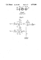
- FIG. 5 is a schematic diagram showing the circuit means for logarithmically converting the current outputs of the photodiodes to voltage signals and means for differentially amplifying the resultant voltage signals to produce a difference signal.
- FIG. 6A is a schematic diagram of three major portions of the electronic subsystem of this invention, including the log conversion and differential amplifier circuit, the correction circuit, and the comparative circuit.
- FIG. 6B is a schematic diagram of the supply regulator circuit and an incandescent light source.
- FIG. 6C is a schematic diagram of an alternative light source comprising two LED's.
- FIG. 7 is an illustration of the transfer characteristic for an IC digital hex inverter.
- FIG. 1 is a perspective view of the comparative colorimeter of the present invention.
- a housing 10 contains the optical and electronic subsystems of this invention.
- a pair of sample tube holders 11, 12 consist of tubular bores disposed vertically in the housing and having closed lower ends and open upper ends in the top wall 13 of the housing. The holders snugly engage two cylindrical sample tubes 5, 6 which contain the sample and standard solutions respectively.
- a row of five indicator lights 15, 16, 17, 18, 19 is provided on the front wall 14 of the housing.
- An on-off button 20 is provided on top wall 13 of the housing.
- the housing is made of a nonbreakable plastic such as acrylonitrile-butadiene-styrene polymer. The device shown in FIG.
- sample tubes 5, 6 are made of polystyrene and have outer dimensions of 12 mm in diameter and 75 mm in length, and an inner diameter of 9 mm.
- the comparative colorimeter of this invention consists of two major subsystems, optical and electronic.
- the important features of the optical subsystem include:
- the tube's exterior and interior may not be concentric, so that the actual path length and direction of a light ray passing through the sample depends on the orientation of the tube.
- a narrowly collimated or focused beam of light from a lamp 200 passes through a sample tube 201 and then through a lens 202 which focuses the beam on a photodetector 203 which is sensitive to a predetermined wavelength.
- a screen 205 having an aperture 206 is disposed between the lamp and tube to prevent stray light from reaching the photodetector.
- a filter 204 is disposed between the lens and photodetector for selecting light of a predetermined wavelength.
- a measurement in absorbance may contain an error of 0.05 to 0.1 as a result of tube defects alone.
- the amount of error is highly dependent on the individual tube under test and its orientation.
- FIGS. 2 and 3 Two designs have been found to be highly effective at minimizing the errors caused by sample tube defects. These designs are shown in FIGS. 2 and 3.
- a first embodiment of the optical subsystem is shown in FIG. 2.
- a pair of photodetectors 30, 31 are positioned at opposite ends of an axial line.
- a light source means 32 such an incandescent lamp, is centered at the midpoint of the axial line.
- a first sample tube 5 and a second sample tube 6 are identically positioned on the axial line on opposite sides of the lamp, between the lamp and an associated photodetector.
- a collimating lens 33A(33B) and a screen 34A(34B) having an aperture 35A(35B) are identically positioned on either side of the lamp between the associated sample tube 5(6) and lamp 32.
- a filter/diffuser 36A(36B) is positioned between the associated sample tube 5(6) and associated photodetector 30(31).
- the object of this first design is to spread the illumination over substantially the entire width of the sample tube so that the net light transmitted to the photodetector is averaged over many scratches and defects and is minimally dependent on the lack of concentricity of the inner diameter and outer diameter of the tube. While the operation of the optical system with respect to sample tube 5 is described herein, the operation with respect to sample tube 6 is identical.
- the collimating lens 33A is positioned between the sample tube 5 and light source 32 and spaced slightly closer to the light source than the focal point of the lens so that the lens transmits a slightly divergent beam to the sample tube.
- the screen 34A prevents stray light beams from reaching the photodetector 30. Further, the height of the aperture 35A is restricted to prevent light from hitting the meniscus of the liquid sample in the tube or the bottom of the tube and reflecting into the photodetector.
- the sample tube 5 is spaced with respect to the lens 33A such that the outer diameter of the divergent beam at the center plane of the tube is equal to or slightly less than the inner diameter d of the tube.
- the sample tube acts as a cylinder lens to focus the beam at a vertical focal line and the photodetector is spaced slightly ahead of the focal line so that the beam strikes a large area of the photodetector. This insures a photodetector signal of large amplitude and averaged value.
- the combination filter/diffuser 36A disposed between the sample tube 5 and photodetector 30 consists of a filter glass 39 for selecting a predetermined wavelength of light and a diffusive sheet or film 40 covering the surface of the filter glass adjacent the photodetector.
- film 40 may be MylarTM film frosted on both sides and about 0.006" (0.15 mm) thick. Because scratches and defects in the sample tube cause light to bounce in a random manner, the diffusive sheet 40 is provided to produce an averaging effect so that the photodetector output is less dependent on defects in the sample tube.
- the photodetector 30 is sensitive to the same predetermined wavelength as the filter glass 39.
- FIG. 2A A preferred embodiment of the filter/diffuser is shown in FIG. 2A.
- Two pieces of filter glass 41, 43 and two sheets of diffusive film 42, 44 are sandwiched together and disposed adjoining a photodetector 45.
- Diffusive sheet 42 is sandwiched between filter glasses 41 and 43, and diffusive sheet 44 is sandwiched between filter glass 43 and photodetector 45.
- This filter/diffuser is preferred because the addition of a second diffusive film separated from the first aids in a more uniform diffusion of the light.
- the use of a second filter glass is necessary in most cases in order to limit the bandwidth of the light transmitted.
- adjoining the photodetector 45 to diffusive layer 44 eliminates light loss and increases the amplitude of the photodetector output.
- a second embodiment of the optical subsystem of this invention is shown in FIG. 3. Again, the design spreads the light beam over a large area of possible defects in the tube.
- a first lens set 50A includes a pair of diametrically opposed lenses 51A, 52A positioned on an axial line between the sample tube 5 and light source 32. Collimating lens 51A is disposed adjacent the light source and has a focal point at the light source. Converging lens 52A is disposed adjacent the sample tube and has a focal point at the center of the sample tube.
- a second lens set 54A includes a second pair of diametrically opposed lenses 55A, 56A positioned on the axial line between the sample tube 5 and photodetector 30. Collimating lens 55A is disposed adjacent the sample tube and has a focal point at the center of the sample tube and converging lens 56A is disposed adjacent the photodetector and has a focal point at the photodetector.
- a filter 57A can be placed between the two lenses 55A, 56A of the second lens so that the light rays pass through the filter as parallel rays. This minimizes refractions at the surface of the filter and thus reduces light loss.
- the first and second lens sets 50B and 54B between the lamp 32, sample tube 6 and photodetector 31, are identical to those of 50A and 54A previously described.
- I max maximum light intensity resulting from the series of readings for a given sample, tube and optical design
- I min minimum light intensity resulting from the series of readings for a given sample, tube and optical design
- I av average light intensity resulting from the series of readings for a given sample, tube and optical design.
- Design 1 was that shown in FIG. 2 with lens 33A having a diameter of 5/16" and a focal length of 3/8".
- Lens 33A was spaced 0.27" from lamp 32
- screen 34A having an aperture 0.125" ⁇ 0.275
- tube 5 was spaced 0.35" from screen 34A
- photodiode 30 was spaced 0.65" from tube 5 (all distances are from center point of element).
- the filter/diffuser used was that shown in FIG. 2A wherein 41 was a 2 mm thick filter glass, model GG-435 by Schott, imported by ESCO Products, Inc. of Oak Ridge, N.J., and 43 was a 4.0 mm thick filter glass, model 5-58 by Corning Glass Works of Corning, N.Y. Each filter glass had a diameter of 5/16".
- the diffuser sheets 42 and 44 were MylarTM film, each 0.006" thick and frosted on both sides.
- the photodiode was adjoining sheet 44.
- Design 2 was that shown in FIG. 3 with lenses 51A, 52A, 55A and 56A each having a diameter of 3/8" and a focal length of 1/2".
- the first lens set was spaced 0.5" from lamp 32
- tube 5 was spaced 0.5" from the first lens set
- lens 55A was spaced 0.5" from tube 5
- lens 56A was spaced 0.25" from lens 55A
- photodiode 30 was spaced, 0.5" from lens 56A (all distances are from center point of element).
- Two filter glasses, the same as 41 and 43 described in design 1 (but without diffusive sheets 42 and 44) were used.
- design 2 the distance between the lenses and sample tube could be changed up to 1/16" (1.6 mm) without changing the photodetector reading significantly.
- the sample tube had to be spaced within 5/1000" (0.13 mm) with respect to the lens and with respect to the axial line extending between the lamp and photodetector to insure a consistent photodetector reading.
- the prior art design was that shown in FIG. 4 with lens 202 having a diameter of 5/16" and a focal length of 3/8".
- Screen 205 had an aperture 206 of 1/10" in height.
- the same two filter glasses described for design 2 were used.
- an incandescent lamp was used, model 158X sold by Gilway of Woburn, Mass.
- the sample tube was made of polystrene having a length of 75 mm, an outer diameter of 75 mm, and an inner diameter of 9 mm.
- the photodiode was model S-1133 sold by Hamamatsu of San Jose, Calif.
- design 1 and design 2 of this invention give substantially better results than the prior art design. While it would appear that design 2 is preferable over design 1, other factors such as cost, size, complexity and the required accuracy of construction mitigate in favor of design 1.
- the electronic subsystem of the present invention performs the following functions:
- the digital gate means drive a plurality of indicator LEDs 1-5 (corresponding to indicator lights 15-19 in FIG. 1) to indicate the relative value of the difference signal with respect to the reference voltages;
- a correction circuit is provided so that the difference signal E 0 is referenced to the threshold voltage E T of the digital gate means.
- the left center red LED 16 and left red LED 15 will light in the same manner as described for those to the right of center.
- the operating voltage V REG for the lamp and the electronic subsystem is stabilized at 2.000 volts by the supply regulator circuit shown in FIG. 6B.
- the circuit includes amplifier A4, capacitors C1, C2, C7, C8, resistors R1, R2, R3 (variable), R4, R7, R22, R23, transistors Q1, Q2, battery V+, and internal regulator V REF .
- a range of battery voltages V+ from 3.0 to 2.1 volts can be accommodated without degrading performance.
- Lamp life is extended substantially by operating the lamp 32 at a constant 2.0 volts.
- the regulator circuit is built around one section of a amplifier A4 specifically intended for voltage regulation.
- A4 in this preferred embodiment is amplifier U4 LM10CLN sold by National Semiconductor of Santa Clara, Calif.
- the LM10CLN drives transistors Q1 and Q2 as required to regulate V REG to exactly 2.000 volts.
- An internal regulator provides a constant V REF of 0.2 volts.
- V REG is divided down to 0.2 volts and then compared to this reference.
- V REF is also used to determine the operating points of the operational amplifiers A1 and A2 as shown in FIG. 6A.
- the two diode currents ID 1 and ID 2 are logarithmically converted to voltage signals and the two voltage signals are differentially amplified.
- the stability of the logarithmic conversion and differental amplification is such that an overall electronic error budget of 0.005 O.D. is not violated over the life of the instrument.
- FIG. 5 shows the log conversion and differential amplifier circuit for generating the difference signal E 0 .
- Light from light source 32 which passes through sample tube 5 and strikes photodiode PD1 generates a current ID 1 .
- light from light source 32 which passes through sample tube 6 and strikes photodiode PD2 generates a current ID 2 .
- the photodiode currents can be expressed as:
- I is the total intensity of light source 32
- f 1 and f 2 are the fractions of light absorbed by the samples in tubes 5 and 6 respectively
- g 1 and g 2 are the fractions of light passing through tubes 5 and 6 which actually reach the photodiodes PD1 and PD2 respectively
- k 1 and k 2 are the efficiencies with which the photodiodes PD1 and PD2 convert the light reaching their surfaces respectively.
- the diode currents I D1 and I D2 constitute optical density signals representative of the optical densities of the samples in tubes 5 and 6 respectively.
- the diode currents I D1 and I D2 are logarithmically converted to voltage signals E 1 and E 2 by a pair of identical log conversion circuits shown in FIGS. 5 and 6A.
- A1 and A2 are from the same package and are identically powered by connection to the regulated supply voltage V REG and decoupling capacitor C3 (as shown for A2) and grounded (as shown for A1). Because the log conversion circuits are identical, the votages E 1 and E 2 may be expressed as:
- the voltage signals E 1 and E 2 are differentially amplified at A3 to produce a difference signal E 0 as set forth below:
- G is the amplifier gain and E C a correction voltage.
- the correction voltage E c is added to the positive input of A3 for reasons discussed hereinafter.
- the ratio of photodiode efficiencies k 2 /k 1 is constant over time given equal wavelength of the incident light, equal temperature and equal reverse bias. Dark current will drift somewhat but is not a limitation in this application.
- the ratio g 2 /g 1 of optic path efficiencies depends on the details of the design and its implementation. If we assume perfect sample tubes and an unchanging rigid geometry, then the ratio g 2 /g 1 is fixed.
- the difference signal E 0 can be represented as follows:
- the difference signal E 0 generated by A 3 is sent to the comparative circuit shown in FIG. 6A, wherein E 0 is compared to a series of predetermined reference voltages to determine to the relative value of the difference signal with respect to the reference voltages.
- the act of comparison is performed by a plurality of low cost digital integrated circuits.
- hex inverters such as the 74HC04 sold by Motorola of Austin, Tex. are used as the digital IC gates means. The hex inverters are used in the configuration shown in FIG. 6A in order to economize on parts count and cost.
- the output from the differential amplifier E 0 is divided by a resistive chain so that the voltage at each node of the chain is directly related to E 0 .
- the resistive chain consists of resistors R12, R13, R14, R15, R16 and R17 arranged in series between V REG and ground. Connected to each node is an input of one of hex inverter gates G1, G2, G3, and G4. Gates G1-G5 are all in the same package and each is connected to the regulated supply voltage V REG and to decoupling capacitor C5 (as shown for G3) and to ground (as shown for G4).
- the gate output is low. Conversely, if the node is below the threshold, then the gate output is high. All of the gates are selected from a single package so they have very nearly the same threshold for a given temperature and supply voltage.
- the comparative circuit further includes indicator LEDs 1-5, resistors R19, R20 and R21, diode D3, transistor Q3, and hex inverter gate G5 as shown in FIG. 6A.
- the indicator LEDs are arranged such that only one LED is on at a time. The operation of the comparative circuit is thus understood by determining its operation under three circumstances, when the optical densities of the two samples are equal, when the optical density of the first sample is greater than the second, and when the optical density of the second sample is greater than the first.
- I D1 is greater than I D2 by up to a first predetermined value, e.g., 0.03 O.D.
- the outputs of G2, G3 and G4 will be high and the output of G1 will be low. All LED's will be off except for the right center red LED 2 which will be on to indicate that the absorbence of the sample in tube 6 is greater than the absorbence of the sample in tube 5, but by no more than 0.03 O.D.
- the absorbence of the sample in tube 6 is greater than that of the sample in tube 5 by at least a second predetermined value, e.g., 0.1 O.D., then the left red LED 1 will be on, and all other LED's off.
- the left center red LED 4 will be on to indicate that the absorbence of the sample in tube 5 is greater than the absorbence of the sample in tube 6 by no more than 0.03 O.D. Further, if the absorbence of the sample in tube 5 is greater than that of the sample in tube 6 by at least 0.1 O.D., then the left red LED 5 will be on and all other LED's off.
- the correction circuit provides both a zeroing mechanism to account for the fact that the two light paths and photodetectors are not truly identical and further provides a compensation factor to account for variations in the threshold voltage E T of the hex inverters used in the comparative circuit.
- the output of the correction circuit shown in FIG. 6A is a correction voltage E c which is applied to the positive input of A3.
- the correction circuit includes a hex inverter G6 from the same package as the hex inverters G1-G5 used in the comparative circuit.
- a trim potentiometer R18 having an output voltage E p , is provided along with resistors R25 and R26 and capacitors C9 and C10.
- the switching threshold of the hex inverter G6 is about one-half of the regulated supply voltage V REG .
- This logic gate is quite abrupt in its action and all of the gates in the package have very nearly the same threshold voltage E T for a given temperature and supply voltage.
- the transfer characteristic of the hex inverter is shown in FIG. 7.
- the slope of the transfer characteristic in the region of E T is the gain of the hex inverter if it is considered as an amplifier.
- the gate output tied to the input, the input and output will stabilize at a value which is called the threshold or switching point E T .
- the absolute value of E T varies from one batch of devices to another, and varies according to time, temperature, and supply voltage. All of the inverters in a package have the same threshold within a few milivolts.
- trim-potentiometer R18 is introduced to the circuit.
- the circuit will stabilize with the input voltage at E T if the trim-pot is adjusted to a value E p , where
- FIG. 6B shows a circuit for driving red LED 6 and red LED 7.
- the operational amplifier U1 25L2 CP is sold by Texas Instruments of Dallas, Tex.
- the differential amplifier U4 LM10CLN is sold by National Semiconductor of Santa Clara, Calif.
- the diode CR1 1N6263 is sold by Hewlett-Packard of Palo Alto, Calif.
- the hex inverter U3 74HC04 is sold by Motorola of Austin, Tex.
- the transistors PN2222, TIP32C, and U2 LM394N, are all sold by National Semiconductor of Santa Clara, Calif.
- the electronic subsystem of this invention it is necessary to set the gain of differential amplifier A3 by selecting appropriate values for the gain resistors R8, R9, R10, and R11. The selection is made so that the indicator LEDs 1-5 come on for predetermined differences in absorbance which are of importance for the test at hand.
- One method for setting the gain of A3 is to use known sample solutions which have been accurately measured in a laboratory spectrophotometric instrument. Alternatively, the required gain can be calculated. To do so, one must understand the difference between the concepts of absorbance and absorptivity. An example of the calculations required to set the gain of A3 is described hereinafter.
- I o is the intensity of light transmitted when the sample tube is filled with completely clear fluid and I is the light transmitted when the actual sample is in place.
- Beer's law relates light absorbance to the properties of the sample under test:
- Equation (14) relates specific differential absorptivity to light intensities. In addition one needs to determine the relationship between light intensities and E 0 , the output of the differential amplifier.
- the characteristic of the LM394 log conversion circuit is that of an ideal silicon diode, for which
- V f forward voltage
- T absolute temperature °K
- I f forward current
- I s saturation current for that diode.
- the two LM394s which are used in the two log amplifiers are housed in the same package and come very well matched from the factory, so that I s is the same for both.
- the forward current I f is just equal to the photodiode current caused by the incident light:
- the differential amplifier extracts the difference in voltage between the two log conversion circuits and amplifies it by a factor G (gain):
- Diode current I D is proportional to light intensity I at the diode:
- the first red light i.e., LED2 or LED4
Landscapes
- Physics & Mathematics (AREA)
- Engineering & Computer Science (AREA)
- Mathematical Physics (AREA)
- Theoretical Computer Science (AREA)
- Spectroscopy & Molecular Physics (AREA)
- Health & Medical Sciences (AREA)
- Life Sciences & Earth Sciences (AREA)
- Chemical & Material Sciences (AREA)
- Analytical Chemistry (AREA)
- Biochemistry (AREA)
- General Health & Medical Sciences (AREA)
- General Physics & Mathematics (AREA)
- Immunology (AREA)
- Pathology (AREA)
- Investigating Or Analysing Materials By Optical Means (AREA)
- Spectrometry And Color Measurement (AREA)
Priority Applications (3)
| Application Number | Priority Date | Filing Date | Title |
|---|---|---|---|
| US06/815,522 US4797000A (en) | 1986-01-02 | 1986-01-02 | Comparative colorimeter |
| EP86309923A EP0228877A3 (fr) | 1986-01-02 | 1986-12-18 | Colorimètre comparatif |
| CA000526502A CA1300923C (fr) | 1986-01-02 | 1986-12-30 | Colorimetre comparatif |
Applications Claiming Priority (1)
| Application Number | Priority Date | Filing Date | Title |
|---|---|---|---|
| US06/815,522 US4797000A (en) | 1986-01-02 | 1986-01-02 | Comparative colorimeter |
Publications (1)
| Publication Number | Publication Date |
|---|---|
| US4797000A true US4797000A (en) | 1989-01-10 |
Family
ID=25218054
Family Applications (1)
| Application Number | Title | Priority Date | Filing Date |
|---|---|---|---|
| US06/815,522 Expired - Lifetime US4797000A (en) | 1986-01-02 | 1986-01-02 | Comparative colorimeter |
Country Status (3)
| Country | Link |
|---|---|
| US (1) | US4797000A (fr) |
| EP (1) | EP0228877A3 (fr) |
| CA (1) | CA1300923C (fr) |
Cited By (21)
| Publication number | Priority date | Publication date | Assignee | Title |
|---|---|---|---|---|
| US5013155A (en) * | 1989-09-26 | 1991-05-07 | Chemetrics, Inc. | Portable spectrophotometric instrument having vial holder and light integrator |
| US5051901A (en) * | 1989-08-21 | 1991-09-24 | Fuji Photo Film Co., Ltd. | Method for judging errors in applying liquid samples during biochemical analysis |
| US5144498A (en) * | 1990-02-14 | 1992-09-01 | Hewlett-Packard Company | Variable wavelength light filter and sensor system |
| US5313268A (en) * | 1992-03-20 | 1994-05-17 | Richard L. Lindemuth | Apparatus and method for testing the level of an item in liquid |
| US5365924A (en) * | 1992-07-31 | 1994-11-22 | Frederick Erdman Association | Method and apparatus for non-invasive cardiovascular diagnosis |
| US5438420A (en) * | 1993-08-09 | 1995-08-01 | Vickers, Incorporated | Monitoring of fluid contamination level wherein the light energy is focused on the fluid passage means |
| WO1995023331A1 (fr) * | 1994-02-25 | 1995-08-31 | Axiom Analytical Inc. | Sonde pour l'analyse d'un echantillon liquide par transmission de lumiere |
| US5528431A (en) * | 1990-07-25 | 1996-06-18 | Cerium Group Limited Of Hill House | Apparatus for obtaining a desired tint |
| US5542421A (en) * | 1992-07-31 | 1996-08-06 | Frederick Erdman Association | Method and apparatus for cardiovascular diagnosis |
| US5973839A (en) * | 1998-03-05 | 1999-10-26 | Hewlett-Packard Company | Optical homogenizer |
| US20040054303A1 (en) * | 2002-07-29 | 2004-03-18 | Taylor Geoffrey L. | Blanching response pressure sore detector apparatus and method |
| US20050185176A1 (en) * | 2004-02-23 | 2005-08-25 | Moran Donald J.Jr. | Determining an analyte by multiple measurements through a cuvette |
| US20060007445A1 (en) * | 2002-08-21 | 2006-01-12 | Alexander Van Geen | Arsenic meter |
| US20070141709A1 (en) * | 2005-12-16 | 2007-06-21 | Artel | Calibrating dispensing device performance for complex and/or non-aqueous liquids |
| US7307718B2 (en) * | 2004-02-23 | 2007-12-11 | Ortho-Clinical Diagnostics, Inc. | Determining an analyte by multiple measurements through a cuvette |
| US20080070317A1 (en) * | 2006-09-15 | 2008-03-20 | Artel, Inc. | Quantitative dual-dye photometric method for determining dilution impact |
| JP2014081280A (ja) * | 2012-10-16 | 2014-05-08 | Horiba Advanced Techno Co Ltd | 色度計 |
| CN105498454A (zh) * | 2015-12-30 | 2016-04-20 | 神华集团有限责任公司 | 一种聚甲醛内气态甲醛的含量测定方法和收集装置 |
| US20170227453A1 (en) * | 2014-08-15 | 2017-08-10 | Tenova Goodfellow Inc. | System and Method for Analyzing Dusty Industrial Off-gas Chemistry |
| US10712240B2 (en) | 2016-04-19 | 2020-07-14 | Ariana Schanzer | Contaminant monitor system and method |
| JPWO2023276230A1 (fr) * | 2021-06-29 | 2023-01-05 |
Families Citing this family (8)
| Publication number | Priority date | Publication date | Assignee | Title |
|---|---|---|---|---|
| DE19645306A1 (de) * | 1996-05-08 | 1997-11-13 | Neuhaus Neotec Maschinen Und A | Verfahren und Vorrichtung zur Steuerung des Röstvorganges zum Rösten von Kaffee |
| EP0915338A3 (fr) * | 1997-11-10 | 2000-03-22 | Jeacle Limited | Analyse photométrique de suspensions d'eau |
| US7116354B2 (en) | 2001-06-20 | 2006-10-03 | Xenogen Corporation | Absolute intensity determination for a light source in low level light imaging systems |
| US7649185B2 (en) | 2002-02-06 | 2010-01-19 | Xenogen Corporation | Fluorescent phantom device |
| US7629573B2 (en) | 2002-02-06 | 2009-12-08 | Xenogen Corporation | Tissue phantom calibration device for low level light imaging systems |
| US9347894B2 (en) | 2010-09-01 | 2016-05-24 | Spectral Instruments Imaging, LLC | Methods and systems for producing visible light and x-ray image data |
| JP2013538350A (ja) | 2010-09-01 | 2013-10-10 | スペクトラル・インストゥルメンツ・イメージング・エルエルシー | 励起光源組立体 |
| CN109991169A (zh) * | 2019-04-15 | 2019-07-09 | 福建新大陆环保科技有限公司 | 一种臭氧浓度测量装置及其测量方法 |
Citations (10)
| Publication number | Priority date | Publication date | Assignee | Title |
|---|---|---|---|---|
| US2501599A (en) * | 1947-11-08 | 1950-03-21 | Shell Dev | Photoelectric colorimeter |
| US2617940A (en) * | 1948-11-12 | 1952-11-11 | Paul A Giguere | Ultraviolet photometric method and apparatus |
| US2873644A (en) * | 1955-02-08 | 1959-02-17 | American Instr Co Inc | Optical system for the measurement of turbidity |
| US3498719A (en) * | 1965-02-18 | 1970-03-03 | Continental Can Co | Photoelectric consistency indicator for pulp |
| US3989383A (en) * | 1975-04-07 | 1976-11-02 | Bio-Technology Instruments Corporation | Reaction detection system |
| US4006990A (en) * | 1974-07-22 | 1977-02-08 | Varian Associates | Convergent light illuminated flow cell for liquid chromatography |
| US4193694A (en) * | 1978-07-03 | 1980-03-18 | Smith Charles R | Photosensitive color monitoring device and method of measurement of concentration of a colored component in a fluid |
| US4195932A (en) * | 1978-07-03 | 1980-04-01 | Abbott Laboratories | Absorption spectrophotometer |
| GB2069692A (en) * | 1980-02-16 | 1981-08-26 | Compur Electronic Gmbh | Photometric method and photometric apparatus for determining courses of reactions |
| US4310249A (en) * | 1979-10-09 | 1982-01-12 | Miles Laboratories, Inc. | Spectrophotometer |
Family Cites Families (3)
| Publication number | Priority date | Publication date | Assignee | Title |
|---|---|---|---|---|
| US3463927A (en) * | 1966-08-02 | 1969-08-26 | Robert W Allington | Apparatus for measuring absorbance differences |
| JPS583073Y2 (ja) * | 1975-07-19 | 1983-01-19 | 株式会社島津製作所 | ブンコウコウドケイ |
| US4502786A (en) * | 1979-12-26 | 1985-03-05 | Helena Laboratories Corporation | Method and apparatus for automated determination of hemoglobin species |
-
1986
- 1986-01-02 US US06/815,522 patent/US4797000A/en not_active Expired - Lifetime
- 1986-12-18 EP EP86309923A patent/EP0228877A3/fr not_active Ceased
- 1986-12-30 CA CA000526502A patent/CA1300923C/fr not_active Expired - Lifetime
Patent Citations (10)
| Publication number | Priority date | Publication date | Assignee | Title |
|---|---|---|---|---|
| US2501599A (en) * | 1947-11-08 | 1950-03-21 | Shell Dev | Photoelectric colorimeter |
| US2617940A (en) * | 1948-11-12 | 1952-11-11 | Paul A Giguere | Ultraviolet photometric method and apparatus |
| US2873644A (en) * | 1955-02-08 | 1959-02-17 | American Instr Co Inc | Optical system for the measurement of turbidity |
| US3498719A (en) * | 1965-02-18 | 1970-03-03 | Continental Can Co | Photoelectric consistency indicator for pulp |
| US4006990A (en) * | 1974-07-22 | 1977-02-08 | Varian Associates | Convergent light illuminated flow cell for liquid chromatography |
| US3989383A (en) * | 1975-04-07 | 1976-11-02 | Bio-Technology Instruments Corporation | Reaction detection system |
| US4193694A (en) * | 1978-07-03 | 1980-03-18 | Smith Charles R | Photosensitive color monitoring device and method of measurement of concentration of a colored component in a fluid |
| US4195932A (en) * | 1978-07-03 | 1980-04-01 | Abbott Laboratories | Absorption spectrophotometer |
| US4310249A (en) * | 1979-10-09 | 1982-01-12 | Miles Laboratories, Inc. | Spectrophotometer |
| GB2069692A (en) * | 1980-02-16 | 1981-08-26 | Compur Electronic Gmbh | Photometric method and photometric apparatus for determining courses of reactions |
Cited By (35)
| Publication number | Priority date | Publication date | Assignee | Title |
|---|---|---|---|---|
| US5051901A (en) * | 1989-08-21 | 1991-09-24 | Fuji Photo Film Co., Ltd. | Method for judging errors in applying liquid samples during biochemical analysis |
| US5013155A (en) * | 1989-09-26 | 1991-05-07 | Chemetrics, Inc. | Portable spectrophotometric instrument having vial holder and light integrator |
| US5144498A (en) * | 1990-02-14 | 1992-09-01 | Hewlett-Packard Company | Variable wavelength light filter and sensor system |
| US5528431A (en) * | 1990-07-25 | 1996-06-18 | Cerium Group Limited Of Hill House | Apparatus for obtaining a desired tint |
| US5313268A (en) * | 1992-03-20 | 1994-05-17 | Richard L. Lindemuth | Apparatus and method for testing the level of an item in liquid |
| US5365924A (en) * | 1992-07-31 | 1994-11-22 | Frederick Erdman Association | Method and apparatus for non-invasive cardiovascular diagnosis |
| US5542421A (en) * | 1992-07-31 | 1996-08-06 | Frederick Erdman Association | Method and apparatus for cardiovascular diagnosis |
| US5438420A (en) * | 1993-08-09 | 1995-08-01 | Vickers, Incorporated | Monitoring of fluid contamination level wherein the light energy is focused on the fluid passage means |
| WO1995023331A1 (fr) * | 1994-02-25 | 1995-08-31 | Axiom Analytical Inc. | Sonde pour l'analyse d'un echantillon liquide par transmission de lumiere |
| US5973839A (en) * | 1998-03-05 | 1999-10-26 | Hewlett-Packard Company | Optical homogenizer |
| US7155273B2 (en) * | 2002-07-29 | 2006-12-26 | Taylor Geoffrey L | Blanching response pressure sore detector apparatus and method |
| US20040054303A1 (en) * | 2002-07-29 | 2004-03-18 | Taylor Geoffrey L. | Blanching response pressure sore detector apparatus and method |
| US7336362B2 (en) | 2002-08-21 | 2008-02-26 | The Trustees Of Columbia University In The City Of New York | Arsenic meter |
| US20060007445A1 (en) * | 2002-08-21 | 2006-01-12 | Alexander Van Geen | Arsenic meter |
| US20090192744A1 (en) * | 2004-02-23 | 2009-07-30 | Moran Jr Donald James | Determining an analyte by multiple measurements through a cuvette |
| US7307718B2 (en) * | 2004-02-23 | 2007-12-11 | Ortho-Clinical Diagnostics, Inc. | Determining an analyte by multiple measurements through a cuvette |
| US20050185176A1 (en) * | 2004-02-23 | 2005-08-25 | Moran Donald J.Jr. | Determining an analyte by multiple measurements through a cuvette |
| US7764372B2 (en) * | 2004-02-23 | 2010-07-27 | Moran Jr Donald James | Determining an analyte by multiple measurements through a cuvette |
| US8003405B2 (en) | 2005-12-16 | 2011-08-23 | Artel, Inc. | Calibrating dispensing device performance for complex and/or non-aqueous liquids |
| US20070141709A1 (en) * | 2005-12-16 | 2007-06-21 | Artel | Calibrating dispensing device performance for complex and/or non-aqueous liquids |
| US20080070317A1 (en) * | 2006-09-15 | 2008-03-20 | Artel, Inc. | Quantitative dual-dye photometric method for determining dilution impact |
| US20100290048A1 (en) * | 2006-09-15 | 2010-11-18 | Artel, Inc. | Quantitative dual-dye photometric method for determining dilution impact |
| US7919327B2 (en) | 2006-09-15 | 2011-04-05 | Artel, Inc. | Quantitative dual-dye photometric method for determining dilution impact |
| US7998747B2 (en) | 2006-09-15 | 2011-08-16 | Artel, Inc. | Quantitative dual-dye photometric method for determining dilution impact |
| JP2014081280A (ja) * | 2012-10-16 | 2014-05-08 | Horiba Advanced Techno Co Ltd | 色度計 |
| US10161851B2 (en) * | 2014-08-15 | 2018-12-25 | Tenova Goodfellow Inc. | System and method for analyzing dusty industrial off-gas chemistry |
| US20170227453A1 (en) * | 2014-08-15 | 2017-08-10 | Tenova Goodfellow Inc. | System and Method for Analyzing Dusty Industrial Off-gas Chemistry |
| US10648901B2 (en) | 2014-08-15 | 2020-05-12 | Tenova Goodfellow Inc. | System and method for analyzing dusty industrial off-gas chemistry |
| CN105498454A (zh) * | 2015-12-30 | 2016-04-20 | 神华集团有限责任公司 | 一种聚甲醛内气态甲醛的含量测定方法和收集装置 |
| CN105498454B (zh) * | 2015-12-30 | 2019-01-11 | 神华集团有限责任公司 | 一种聚甲醛内气态甲醛的含量测定方法和收集装置 |
| US10712240B2 (en) | 2016-04-19 | 2020-07-14 | Ariana Schanzer | Contaminant monitor system and method |
| JPWO2023276230A1 (fr) * | 2021-06-29 | 2023-01-05 | ||
| WO2023276230A1 (fr) * | 2021-06-29 | 2023-01-05 | ソニーグループ株式会社 | Dispositif de mesure de densité |
| JP7786459B2 (ja) | 2021-06-29 | 2025-12-16 | ソニーグループ株式会社 | 濃度測定装置 |
| US12613182B2 (en) | 2021-06-29 | 2026-04-28 | Sony Group Corporation | Concentration measurement device |
Also Published As
| Publication number | Publication date |
|---|---|
| EP0228877A3 (fr) | 1988-08-03 |
| EP0228877A2 (fr) | 1987-07-15 |
| CA1300923C (fr) | 1992-05-19 |
Similar Documents
| Publication | Publication Date | Title |
|---|---|---|
| US4797000A (en) | Comparative colorimeter | |
| US4171909A (en) | Apparatus for measuring light intensities | |
| US5872361A (en) | Turbidimeter with non-imaging optical concentrator | |
| CN100378449C (zh) | 测试流体特性的装置和方法 | |
| US4286327A (en) | Apparatus for near infrared quantitative analysis | |
| US6803594B2 (en) | Measuring system for optically determining concentration of turbid liquid samples | |
| US5073720A (en) | Liquid level and volume measurement device | |
| EP0205698A1 (fr) | Réflectomètre compact | |
| JPS63175744A (ja) | 光吸収分析装置 | |
| US20250146869A1 (en) | Spectrometer with built-in calibration path | |
| ATE112852T1 (de) | Kalibriereinrichtung für ein nichtdispersives infrarot-fotometer. | |
| JP4306948B2 (ja) | 透過光屈折計 | |
| US7978325B2 (en) | Biochemical analyzer | |
| US4014612A (en) | Photometric measuring apparatus | |
| AU647317B2 (en) | Spectrometer for conducting turbidimetric and colormetric measurements | |
| JPH11511557A (ja) | 環境光の下での標本の特性を決定する方法と装置 | |
| AU2002310007B2 (en) | Optical turbidimeter with a lens tube | |
| EP0185285A2 (fr) | Appareil de mesure de niveau du liquide | |
| Johnston | Gas monitors employing infrared LEDs | |
| US3854045A (en) | Measuring the dust concentration in air | |
| US4484819A (en) | Reflectometer | |
| RU2109269C1 (ru) | Оптический абсорбционный газоанализатор | |
| US6768549B1 (en) | Ampoule analyzer apparatus | |
| US4946282A (en) | Transparency transmissivity measurement device | |
| CA2294188C (fr) | Systeme d'etalonnage pour un tube de photomultiplicateur |
Legal Events
| Date | Code | Title | Description |
|---|---|---|---|
| AS | Assignment |
Owner name: ARTEL, 28 DEPOT STREET, SOUTH WINDHAM, MAINE, 0408 Free format text: ASSIGNMENT OF ASSIGNORS INTEREST.;ASSIGNOR:CURTIS, RICHARD H.;REEL/FRAME:004501/0976 Effective date: 19851231 |
|
| STCF | Information on status: patent grant |
Free format text: PATENTED CASE |
|
| FEPP | Fee payment procedure |
Free format text: PAYOR NUMBER ASSIGNED (ORIGINAL EVENT CODE: ASPN); ENTITY STATUS OF PATENT OWNER: SMALL ENTITY |
|
| CC | Certificate of correction | ||
| FPAY | Fee payment |
Year of fee payment: 4 |
|
| FPAY | Fee payment |
Year of fee payment: 8 |
|
| FPAY | Fee payment |
Year of fee payment: 12 |