US4800484A - Computing installation with automatic terminal switching and a terminal adapted to such switching - Google Patents
Computing installation with automatic terminal switching and a terminal adapted to such switching Download PDFInfo
- Publication number
- US4800484A US4800484A US06/623,214 US62321484A US4800484A US 4800484 A US4800484 A US 4800484A US 62321484 A US62321484 A US 62321484A US 4800484 A US4800484 A US 4800484A
- Authority
- US
- United States
- Prior art keywords
- computer
- computers
- access
- printer
- terminal unit
- Prior art date
- Legal status (The legal status is an assumption and is not a legal conclusion. Google has not performed a legal analysis and makes no representation as to the accuracy of the status listed.)
- Expired - Fee Related
Links
Images




Classifications
-
- G—PHYSICS
- G06—COMPUTING OR CALCULATING; COUNTING
- G06F—ELECTRIC DIGITAL DATA PROCESSING
- G06F13/00—Interconnection of, or transfer of information or other signals between, memories, input/output devices or central processing units
- G06F13/38—Information transfer, e.g. on bus
- G06F13/40—Bus structure
- G06F13/4004—Coupling between buses
- G06F13/4022—Coupling between buses using switching circuits, e.g. switching matrix, connection or expansion network
-
- G—PHYSICS
- G06—COMPUTING OR CALCULATING; COUNTING
- G06F—ELECTRIC DIGITAL DATA PROCESSING
- G06F13/00—Interconnection of, or transfer of information or other signals between, memories, input/output devices or central processing units
- G06F13/14—Handling requests for interconnection or transfer
Definitions
- the present invention relates to computing installations likely to incorporate several computers operating independently intended to be associated with input or output terminal units (such as card readers, disk units, printers, modems, . . . ).
- each independent computer is provided with terminal units which are assigned to it, even when each of these terminal units was able to be used possibly through an adapter, with any one of the computers.
- Devices are however known for mechanically switching one terminal unit to one or other of the computers so as to fulfil the requirements for a particular computing program. This mechanical switching has switching defects inherent in the technology and, in addition, is very ill suited to the random nature of the requirement of connecting different computers to a given terminal unit.
- the invention provides more especially an installation comprising several digital computers and a terminal unit capable of cooperating with any one of the computers, characterized in that it comprises means for causing, in response to an access request to the terminal unit emitted by one of the computers, the connection to be established between the computer and the terminal unit, if this latter is free, and for forbidding access to the terminal unit by other computers during a given time or during the occupancy time.
- the invention may be put into effect in numerous ways, whenever there is a number of computers greater than the number of terminal units of the same type.
- Several terminal units of different types may each be equipped so as to be able to be used alternately by the different computers.
- the means for establishing the connection will obviously depend on the nature of the terminal unit. In some cases, for example that of an input terminal unit such as a reader, it will be sufficient to establish the connection, the computer subsequently providing the necessary commands. In other cases, for example that of a printer, additional commands will be required for separating the data coming from the different computers. This separation may more especially be achieved by page jumping or by entry of appropriate reference indications.
- FIG. 1 is a block drawing diagram showing the switching means provided in the installation for allowing the access by three computers belonging to the installation to a common input terminal unit, formed by a card reader,
- FIG. 2 is a block diagram showing an installation with four computers and two standardized terminal units
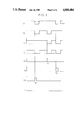
- FIG. 3 is a timing diagram of the signals exchanged in the installation during establishment of the dialogue between the computers and the card reader,
- FIGS. 4a and 4b are block diagrams showing the logic and the switching means provided in the installation for allowing access by two computers belonging to the installation to a common output terminal unit, formed by a printer,
- FIG. 5 is a timing diagram of the signals exchanged between computers and printer, the different lines showing the shape of the signals which appear at the points of FIGS. 4a and 4b bearing the same designation.
- switching means intended to be connected, on the one hand, to a connector 10 equipping the card reader and on the other hand to connectors 12a, 12b and 12c each equipping one of the computers (not shown).
- the means shown in FIG. 1 are provided for allowing access by a computer to the card reader when the reader is free, then for preventing access by the other computers while the first one dialogues with the card reader.
- the means shown use the fact that the dialogue is only established on reception by the computer of a "ready” signal from the reader.
- the means inhibit reception of the signal by the other computers once an access request has been received from the first computer.
- This result is attained, by inserting, between the access request terminal 13 (emission of the signal frequently called “pick command") and terminal 14 receiving the "ready” signal on the corresponding connector, a circuit which is the same for each of the computers.
- Only the circuit 15a associated with the first computer will be described. It comprises, from pin 13a, a shaping circuit 16a which will be generally a Schmitt trigger which drives an AND gate 17a with as many inputs as there are computers. The output of this gate 17a is applied to a memory, formed in FIG.
- a monostable FF 18a whose holding time is compatible with the reading time: this holding time will be for example four seconds.
- a circuit could be used which changes state on reception of the signal from gate 17a and remains in this state until the card reader is freed.
- the other two inputs of the AND gate 17a are connected to the Q outputs of the monostable FFs 18a and 18c controlled by the access request signals on the other two computers.
- the Q output of monostable 18a is applied to the AND gates 17b and 17C of the circuits associated with the other computers.
- the Q output of the monostable FF 18a drives a block 19a for allowing or inhibiting the arrival of the "ready" signal supplied by a pin 20 of the connector 10 of the reader, at the reception terminal 14a.
- Block 19a comprises a gate 21a which receives on one input the signal from the Q output of the monostable FF, and on the other input the "ready” signal from the reader.
- the output of the AND gate 21a is transmitted, by an OR gate 22a, to pin 14a.
- the second input of gate 22a is connected to the output of a NOR gate 23 whose inputs are connected to the three AND gates 17a, 17b and 17c and whose output forms the "pick command" order applied to the corresponding pin 24 of the connector 10 of the reader.
- the device which has just been described operates in the following way. It will be first of all assumed that the reader is free, being connected to none of the computers.
- the three monostable FF's 18a, 18b and 18c are in the rest position. Their Q outputs apply high levels to gates 17.
- the switching means shown in FIG. 1 may be used such as they are or with limited modifications in very different installations.
- FIGS. 4a and 4b are provided for allowing access to a printer by two computers A and B. For the installation given by way of example, nineteen signals are exchanged between the computer interface and printer 34.
- data demand data transmission signal.
- data strobe data validation signal.
- data 1-7 data signals (code ASCII).
- paper instruction signal for unrolling the paper.
- top top of page position.
- the other signals are status data.
- monostable 44 is set to 1 and forces flip flop 46 to 1, causing immediate connection to computer A;
- monostable 42 if monostable 42 is at 1 (which indicates that printer 34 is occupied by computer B) monostable 44 will only be switched on detection of the top signal (top of page). The switching of 44 stores the state of 42 and causes flip flop 46 to be set which ensures switching.
- flip flop 46 is forced to zero: the printer is immediately switched to computer B.
- flip flop 50 is at 1 (which indicates that computer B was using the printer)
- flip flop 52 is set and forces a page jump (generation of the "paper instruction" signal with resetting of data 1-7).
- flip flop 52 is reset, causing 50 then 46 to be reset. The printer is then switched to computer B.
- the timing diagram of FIG. 5 shows, by way of example, the spacing out of the signals following a request for switching printer 34 to computer A, at time T1 when the monostable 42 is in the high state (case 1b above). Switching to computer A then occurs only in response to the detection of the top signal at time T2.
- the retriggerable monostable 40 remains set for a given time (20 seconds for example) after time T3 at the end of transfer from computer A.
- the resetting of monostable 40 causes monostable 48 to be set, for a very short time with respect to that of 40 (200 ns instead of 20 seconds for example) and the emission of a "paper instruction" page jump at time T4. Then, on the appearance of the top signal, at time T5 the printer is again connected to computer B and the "paper instruction" signal ends.
- FIG. 2 shows in another embodiment, an installation comprising a computing center with three computers 26a, 26b and 26c working in parallel and a stand-by computer 26d.
- the computing center may for example form a simulator for simulating the behavior of a pressurized water power reactor.
- the computing center may then provide:
- the computing center comprises numerous industrial inputs/outputs 28 to the control room, high capacity stores (with hard disk 29 and magnetic tapes 30 for example), a character generator 31, etc. . . . as well as a RAM 32 accessible by all the computers and in addition to the individual stores such as 33a of the CPU's.
- Two terminal units of the installation are little used namely printer 34 and card reader 35. Though they are in fact indispensable for initialization and the daily start up of the simulator, the rest of the time they are scarcely used except on the subsidiary computing center using computer 26d and during maintenance work.
- the card reader 35 is used during the initialization, start up and maintenance phases of computers 26a-c and on the subsidiary computing center 26d for the soft ware development. No priority has been defined: the switching is made automatically to the computer which requests it. An system indicating that the cord reader is busy prevents any further switching as long as the card reader is occupied.
- printer 34 is normally connected to the computer 26a of the simulator so as to allow real time printing of the messages from the monitor which is not capable of editing its messages a posteriori. But the printer is used especially as output terminal unit for the subsidiary computing center, for batch work on the simulator and for maintenance operations.
- the standardization of the card reader 35 and printer 34 is effected by assigning to each switching means 36 or 37 of the kind shown in FIG. 1, connected to couplers 38a-38d of the computers, each connected to a control terminal 39.
- the signals exchanged between the computer requesting access and the standardized terminal unit depend on the nature of the hardware.
- the connection between the card reader 35 and the coupler 38a/d of a computer is provided by nineteen signals, eighteen of which are sent by the reader to the coupler.
- Coupler 38a-d only sends a single signal to the reader 35, the reading request signal (pick command).
- the computer finds that the reader is in "Ready” condition.
- the switch 10 then signals to the other three computers that the reader is “No ready” ("ready" signal at .0.). Moreover, so as to avoid any conflict between computers and reader, the modified "ready" signal is stored for a time T.
- the "ready” signal is modified from the "pick command” signals coming from the different computers.
- the "pick command” signal is not modified if the computer is exchanging data with the reader; on the other hand, this signal is not transmitted if the reader is already connected to another computer or if period T is not finished.
- the timing diagram of FIG. 3 shows possible staggering of use of the card reader by the three computers.
- Lines A 1 , B 1 , C 1 , and D 1 give the logic level of the "ready" signal arriving at the couplers of the computers;
- lines A 2 , B 2 , C 2 , and D 2 give the "pick command" signals emitted by these couplers.
- the gates and timing monostables may be formed with TTL logic and the switch may be fitted in a computer cabinet.
- the power supply may be provided from the reader so as to avoid having to switch on the computer when it is desired to connect the reader to the other computers.
- the connections may be formed by conventional flat connectors.
- the installation could comprise a number of computers different from four and the standardized terminal units could be increased in number and comprise for example a magnetic tape unit.
Landscapes
- Engineering & Computer Science (AREA)
- Theoretical Computer Science (AREA)
- Physics & Mathematics (AREA)
- General Engineering & Computer Science (AREA)
- General Physics & Mathematics (AREA)
- Computer Hardware Design (AREA)
- Mathematical Physics (AREA)
- Accessory Devices And Overall Control Thereof (AREA)
- Computer And Data Communications (AREA)
- Selective Calling Equipment (AREA)
- Studio Circuits (AREA)
- Communication Control (AREA)
- Multi Processors (AREA)
- Management, Administration, Business Operations System, And Electronic Commerce (AREA)
- Small-Scale Networks (AREA)
Applications Claiming Priority (2)
| Application Number | Priority Date | Filing Date | Title |
|---|---|---|---|
| FR8310247 | 1983-06-21 | ||
| FR8310247A FR2547934B1 (fr) | 1983-06-21 | 1983-06-21 | Installation de calcul a commutation automatique de peripheriques et peripherique propre a de telles commutations |
Publications (1)
| Publication Number | Publication Date |
|---|---|
| US4800484A true US4800484A (en) | 1989-01-24 |
Family
ID=9290010
Family Applications (1)
| Application Number | Title | Priority Date | Filing Date |
|---|---|---|---|
| US06/623,214 Expired - Fee Related US4800484A (en) | 1983-06-21 | 1984-06-21 | Computing installation with automatic terminal switching and a terminal adapted to such switching |
Country Status (7)
| Country | Link |
|---|---|
| US (1) | US4800484A (de) |
| EP (1) | EP0129487B1 (de) |
| JP (1) | JPS6054064A (de) |
| AT (1) | ATE34239T1 (de) |
| CA (1) | CA1216678A (de) |
| DE (1) | DE3471187D1 (de) |
| FR (1) | FR2547934B1 (de) |
Cited By (7)
| Publication number | Priority date | Publication date | Assignee | Title |
|---|---|---|---|---|
| US5101496A (en) * | 1988-01-22 | 1992-03-31 | Kabushiki Kaisha Toshiba | Printer interface system which selectively receives horizontal sync signal and dot clock signals from plural printing image data |
| US5168568A (en) * | 1989-02-06 | 1992-12-01 | Compaq Computer Corporation | Delaying arbitration of bus access in digital computers |
| US5535395A (en) * | 1992-10-02 | 1996-07-09 | Compaq Computer Corporation | Prioritization of microprocessors in multiprocessor computer systems |
| US5553310A (en) * | 1992-10-02 | 1996-09-03 | Compaq Computer Corporation | Split transactions and pipelined arbitration of microprocessors in multiprocessing computer systems |
| US5553248A (en) * | 1992-10-02 | 1996-09-03 | Compaq Computer Corporation | System for awarding the highest priority to a microprocessor releasing a system bus after aborting a locked cycle upon detecting a locked retry signal |
| EP0991240A3 (de) * | 1998-09-30 | 2003-06-25 | Hewlett-Packard Company, A Delaware Corporation | Verfahren zur Mehrfachzugriffsvermeidung für paketorientierte Steuerungsprotokolle |
| US20050207338A1 (en) * | 2004-03-22 | 2005-09-22 | Aten International Co., Ltd. | Keyboard video mouse switch for multiple chaining and a method for switching electrical signals thereof |
Families Citing this family (2)
| Publication number | Priority date | Publication date | Assignee | Title |
|---|---|---|---|---|
| GB8510791D0 (en) * | 1985-04-29 | 1985-06-05 | Moller C H | Automatic computer peripheral switch |
| IL89355A0 (en) * | 1988-02-24 | 1989-09-10 | Ardent Computer Corp | Method and apparatus for controlling access to a system bus |
Citations (9)
| Publication number | Priority date | Publication date | Assignee | Title |
|---|---|---|---|---|
| US3214739A (en) * | 1962-08-23 | 1965-10-26 | Sperry Rand Corp | Duplex operation of peripheral equipment |
| US3253262A (en) * | 1960-12-30 | 1966-05-24 | Bunker Ramo | Data processing system |
| US3934230A (en) * | 1972-12-28 | 1976-01-20 | Compagnie Industrielle Des Telecommunications Cit-Alcatel | Automatic selector for peripheral equipment |
| US4004277A (en) * | 1974-05-29 | 1977-01-18 | Gavril Bruce D | Switching system for non-symmetrical sharing of computer peripheral equipment |
| US4096572A (en) * | 1975-09-30 | 1978-06-20 | Tokyo Shibaura Electric Co., Ltd. | Computer system with a memory access arbitrator |
| US4442502A (en) * | 1981-03-30 | 1984-04-10 | Datapoint Corporation | Digital information switching system |
| US4485436A (en) * | 1978-11-30 | 1984-11-27 | International Business Machines Corporation | System for selecting interfaces on a priority basis |
| US4495569A (en) * | 1982-06-28 | 1985-01-22 | Mitsubishi Denki Kabushiki Kaisha | Interrupt control for multiprocessor system with storage data controlling processor interrupted by devices |
| US4623883A (en) * | 1984-12-10 | 1986-11-18 | Ncr Corporation | Automatic communications switch |
Family Cites Families (5)
| Publication number | Priority date | Publication date | Assignee | Title |
|---|---|---|---|---|
| JPS55118124A (en) * | 1979-03-05 | 1980-09-10 | Fujitsu Ltd | Interface switch |
| US4314164A (en) * | 1979-11-05 | 1982-02-02 | Gte Automatic Electric Labs Inc. | Computer channel access circuit for multiple input-output devices |
| JPS57168366A (en) * | 1981-04-09 | 1982-10-16 | Mitsubishi Electric Corp | Dispersed type computer system |
| JPS5813070A (ja) * | 1981-07-16 | 1983-01-25 | Mitsubishi Electric Corp | 書画受信装置 |
| JPS59108143A (ja) * | 1982-12-14 | 1984-06-22 | Toshiba Corp | マルチチヤンネル切換機能付プリンタ装置 |
-
1983
- 1983-06-21 FR FR8310247A patent/FR2547934B1/fr not_active Expired
-
1984
- 1984-06-20 JP JP59127254A patent/JPS6054064A/ja active Pending
- 1984-06-20 CA CA000457053A patent/CA1216678A/en not_active Expired
- 1984-06-21 AT AT84401298T patent/ATE34239T1/de not_active IP Right Cessation
- 1984-06-21 EP EP84401298A patent/EP0129487B1/de not_active Expired
- 1984-06-21 US US06/623,214 patent/US4800484A/en not_active Expired - Fee Related
- 1984-06-21 DE DE8484401298T patent/DE3471187D1/de not_active Expired
Patent Citations (9)
| Publication number | Priority date | Publication date | Assignee | Title |
|---|---|---|---|---|
| US3253262A (en) * | 1960-12-30 | 1966-05-24 | Bunker Ramo | Data processing system |
| US3214739A (en) * | 1962-08-23 | 1965-10-26 | Sperry Rand Corp | Duplex operation of peripheral equipment |
| US3934230A (en) * | 1972-12-28 | 1976-01-20 | Compagnie Industrielle Des Telecommunications Cit-Alcatel | Automatic selector for peripheral equipment |
| US4004277A (en) * | 1974-05-29 | 1977-01-18 | Gavril Bruce D | Switching system for non-symmetrical sharing of computer peripheral equipment |
| US4096572A (en) * | 1975-09-30 | 1978-06-20 | Tokyo Shibaura Electric Co., Ltd. | Computer system with a memory access arbitrator |
| US4485436A (en) * | 1978-11-30 | 1984-11-27 | International Business Machines Corporation | System for selecting interfaces on a priority basis |
| US4442502A (en) * | 1981-03-30 | 1984-04-10 | Datapoint Corporation | Digital information switching system |
| US4495569A (en) * | 1982-06-28 | 1985-01-22 | Mitsubishi Denki Kabushiki Kaisha | Interrupt control for multiprocessor system with storage data controlling processor interrupted by devices |
| US4623883A (en) * | 1984-12-10 | 1986-11-18 | Ncr Corporation | Automatic communications switch |
Cited By (10)
| Publication number | Priority date | Publication date | Assignee | Title |
|---|---|---|---|---|
| US5101496A (en) * | 1988-01-22 | 1992-03-31 | Kabushiki Kaisha Toshiba | Printer interface system which selectively receives horizontal sync signal and dot clock signals from plural printing image data |
| US5168568A (en) * | 1989-02-06 | 1992-12-01 | Compaq Computer Corporation | Delaying arbitration of bus access in digital computers |
| US5535395A (en) * | 1992-10-02 | 1996-07-09 | Compaq Computer Corporation | Prioritization of microprocessors in multiprocessor computer systems |
| US5553310A (en) * | 1992-10-02 | 1996-09-03 | Compaq Computer Corporation | Split transactions and pipelined arbitration of microprocessors in multiprocessing computer systems |
| US5553248A (en) * | 1992-10-02 | 1996-09-03 | Compaq Computer Corporation | System for awarding the highest priority to a microprocessor releasing a system bus after aborting a locked cycle upon detecting a locked retry signal |
| EP0991240A3 (de) * | 1998-09-30 | 2003-06-25 | Hewlett-Packard Company, A Delaware Corporation | Verfahren zur Mehrfachzugriffsvermeidung für paketorientierte Steuerungsprotokolle |
| US20050207338A1 (en) * | 2004-03-22 | 2005-09-22 | Aten International Co., Ltd. | Keyboard video mouse switch for multiple chaining and a method for switching electrical signals thereof |
| GB2412456A (en) * | 2004-03-22 | 2005-09-28 | Aten Int Co Ltd | A Keyboard Video Mouse (KVM) switch for multiple chaining. |
| GB2412456B (en) * | 2004-03-22 | 2006-05-24 | Aten Int Co Ltd | A keyboard video mouse switch for multiple chaining and a method for switching electrical signals thereof |
| US7584309B2 (en) | 2004-03-22 | 2009-09-01 | Aten International Co., Ltd. | Keyboard video mouse switch for multiple chaining and a method for switching electrical signals thereof |
Also Published As
| Publication number | Publication date |
|---|---|
| ATE34239T1 (de) | 1988-05-15 |
| EP0129487B1 (de) | 1988-05-11 |
| CA1216678A (en) | 1987-01-13 |
| JPS6054064A (ja) | 1985-03-28 |
| EP0129487A1 (de) | 1984-12-27 |
| FR2547934B1 (fr) | 1988-12-02 |
| FR2547934A1 (fr) | 1984-12-28 |
| DE3471187D1 (en) | 1988-06-16 |
Similar Documents
| Publication | Publication Date | Title |
|---|---|---|
| EP0404414B1 (de) | Einrichtung und Verfahren zur Adresszuweisung an SCSI-unterstützte Peripheriegeräte | |
| US4716526A (en) | Multiprocessor system | |
| US6243834B1 (en) | Apparatus and method for capturing information off a plurality of bi-directional communications buses | |
| US4792896A (en) | Storage controller emulator providing transparent resource sharing in a computer system | |
| US4800484A (en) | Computing installation with automatic terminal switching and a terminal adapted to such switching | |
| EP0520768A2 (de) | Emulationsverfahren für eine vom Rechnersystem entfernten Konsole | |
| US3618031A (en) | Data communication system | |
| US4688171A (en) | Serial bus for master/slave computer system | |
| EP3001323A1 (de) | Serielle Peripherieschnittstelle | |
| JPH05189104A (ja) | 並列インタフェース | |
| US5134706A (en) | Bus interface interrupt apparatus | |
| US3828326A (en) | Adapter for interfacing a programmable controller to a data processor channel | |
| US3629831A (en) | Data transmission controller for central to remote system | |
| JPS58502027A (ja) | 低デ−タ転送率の直列入出力インタ−フェイスをモニタするようにされた周辺装置 | |
| KR100239716B1 (ko) | 소형 컴퓨터 시스템 인터페이스 콘트롤러의 진단 테스트 장치 | |
| CN101699416A (zh) | 主机与多卡座读卡器的通信方法和系统 | |
| EP0426081B1 (de) | Programmierbare Steuerungsvorrichtung mit Unterbrechungssteuerungsgerät zur Prioritätsbestimmung von Unterbrechungsanforderungen von einer Vielzahl von Ein-/Ausgabeeinrichtungen und zur Unterbrechungsvektorerzeugung | |
| DE10007970A1 (de) | Vorrichtung und Verfahren zum Umwandeln von Unterbrechungstransaktionen in Unterbrechungssignale, um Unterbrechungen an IA-32-Prozessoren zu verteilen | |
| DE69817539T2 (de) | Pc-chipanordnungverbindungsbus | |
| GB1574470A (en) | Intelligent input-output interface control unit for input-output system | |
| CA1286415C (en) | Multiprocessor level change synchronization apparatus | |
| EP0121603B1 (de) | Anschluss eines Personalcomputers an ein System mit Anzeigeeinrichtungen und einem Verarbeitungsrechner | |
| DE69307332T2 (de) | Uebertragungsverfahren mit einem scsi-busgeraet ohne zugewiesene scsi-adresse | |
| EP0060535A2 (de) | Multiprozessor-Netzwerk | |
| CN119127751B (zh) | Dma控制器、芯片、根复合体及端点设备 |
Legal Events
| Date | Code | Title | Description |
|---|---|---|---|
| AS | Assignment |
Owner name: ELECTRICITE DE FRANCE (SERVICE NATIONAL)2, RUE LOU Free format text: ASSIGNMENT OF ASSIGNORS INTEREST.;ASSIGNORS:BAIZE, DOMINIQUE;CLEAUD, MAURICE;MINARD, SERGE;REEL/FRAME:004317/0006 Effective date: 19840822 Owner name: ELECTRICITE DE FRANCE (SERVICE NATIONAL),FRANCE Free format text: ASSIGNMENT OF ASSIGNORS INTEREST;ASSIGNORS:BAIZE, DOMINIQUE;CLEAUD, MAURICE;MINARD, SERGE;REEL/FRAME:004317/0006 Effective date: 19840822 |
|
| FEPP | Fee payment procedure |
Free format text: PAYOR NUMBER ASSIGNED (ORIGINAL EVENT CODE: ASPN); ENTITY STATUS OF PATENT OWNER: LARGE ENTITY |
|
| REMI | Maintenance fee reminder mailed | ||
| LAPS | Lapse for failure to pay maintenance fees | ||
| FP | Lapsed due to failure to pay maintenance fee |
Effective date: 19930124 |
|
| STCH | Information on status: patent discontinuation |
Free format text: PATENT EXPIRED DUE TO NONPAYMENT OF MAINTENANCE FEES UNDER 37 CFR 1.362 |