US4811335A - Broadband/narrow-band switching network of the time-space-time type and time and space switching stages for broadband/narrow-band channels - Google Patents
Broadband/narrow-band switching network of the time-space-time type and time and space switching stages for broadband/narrow-band channels Download PDFInfo
- Publication number
- US4811335A US4811335A US07/021,327 US2132787A US4811335A US 4811335 A US4811335 A US 4811335A US 2132787 A US2132787 A US 2132787A US 4811335 A US4811335 A US 4811335A
- Authority
- US
- United States
- Prior art keywords
- switching
- broadband
- time
- narrow
- channels
- Prior art date
- Legal status (The legal status is an assumption and is not a legal conclusion. Google has not performed a legal analysis and makes no representation as to the accuracy of the status listed.)
- Expired - Lifetime
Links
- 230000015654 memory Effects 0.000 claims description 39
- 239000011159 matrix material Substances 0.000 claims description 6
- 239000013307 optical fiber Substances 0.000 description 4
- RYGMFSIKBFXOCR-UHFFFAOYSA-N Copper Chemical compound [Cu] RYGMFSIKBFXOCR-UHFFFAOYSA-N 0.000 description 3
- 230000005540 biological transmission Effects 0.000 description 3
- 230000002452 interceptive effect Effects 0.000 description 2
- 230000003466 anti-cipated effect Effects 0.000 description 1
- 229910052802 copper Inorganic materials 0.000 description 1
- 239000010949 copper Substances 0.000 description 1
- 238000010586 diagram Methods 0.000 description 1
- 239000000835 fiber Substances 0.000 description 1
- 230000003287 optical effect Effects 0.000 description 1
Images


Classifications
-
- H—ELECTRICITY
- H04—ELECTRIC COMMUNICATION TECHNIQUE
- H04Q—SELECTING
- H04Q11/00—Selecting arrangements for multiplex systems
- H04Q11/04—Selecting arrangements for multiplex systems for time-division multiplexing
- H04Q11/0428—Integrated services digital network, i.e. systems for transmission of different types of digitised signals, e.g. speech, data, telecentral, television signals
- H04Q11/0478—Provisions for broadband connections
-
- H—ELECTRICITY
- H04—ELECTRIC COMMUNICATION TECHNIQUE
- H04J—MULTIPLEX COMMUNICATION
- H04J2203/00—Aspects of optical multiplex systems other than those covered by H04J14/05 and H04J14/07
- H04J2203/0001—Provisions for broadband connections in integrated services digital network using frames of the Optical Transport Network [OTN] or using synchronous transfer mode [STM], e.g. SONET, SDH
- H04J2203/0003—Switching fabrics, e.g. transport network, control network
Definitions
- the invention relates to a switching system for broadband and narrow-band channels, broadband and narrow-band signals being applied to an input end of the switching system and a time-division multiplex signal which can accommodate a plurality of broadband channels and one or more narrow-band channels being generated at an output end of the switching system.
- a telecommunication system including a switching system for distributing broadband channels, for example broadcast-TV-channels, and for switching broadband (for example video-phone) and narrow-band channels (for example telephone) is disclosed in the published European Patent Application No. EP 0,071,057.
- the switching system described there includes a space-division multiplex stage to show input the broadband and narrow-band channels are applied.
- the present invention has for its object to provide a switching system in which both the broadband and the narrow-band channels utilise the same switching system, but in which the control for each type of channels is separate.
- the invention provides a switching system for broadband and narrow-band channels as set forth in the opening paragraph, characterized in that the switching system includes one or more ingoing time switching stages, that each time switching stage includes a first data store and first routing memory coupled thereto for switching-through in time-division multiplex broadband signal sources connected to inputs of the first data store, that each time switching stage includes a second data store and a second routing memory connected thereto for switching-through and multiplexing into a broadband channel narrow band signal sources connected to inputs of the second data store, that outputs of the second data store are connected to second inputs of the first data store for switching in time-division multiplex the narrow-band channels multiplexed into broadband channels together with the broadband channels connected to the first inputs, that the switching system further includes one or more space switching stages connected to outputs of the ingoing time switching stages for switching through
- the invention has the advantage that the control for the narrow-band channels need not be as fast (up to a factor of approximately 300) as the control for the broadband channels.
- a further advantage is that, as is also the case in the system described in the above-mentioned European Patent Application No. EP 0.071,057, a multiplexer is not required for each individual subscriber.
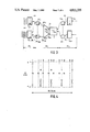
- FIGS. 1a to 1d are an illustration of the anticipated evolution of the ISDN to IBCN (Integrated Broadband Communication Network), the invention providing a switching system for the latter network concept;
- IBCN Integrated Broadband Communication Network
- FIG. 2 is a circuit diagram of the telecommunication traffic and the composition of that traffic in an IBCN network according to the invention
- FIG. 3 shows a switching system of the time-space-time type according to the invention
- FIG. 4 shows an arrangement according to the invention of frame and sub-frame of the time-division multiplex signal to be switched
- FIG. 5 shows an ingoing time switching stage according to the invention
- FIG. 6 shows a space switching stage according to the invention
- FIG. 7 shows an outgoing time switching stage according to the invention.
- Digitising the telephone network opened the possibility of providing a greater diversity of services to the subscribers.
- the possibility of utilising the network also for data traffic was created.
- the what is commonly referred to as the Integrated Service Digital Network (ISDN) became possible.
- ISDN Integrated Service Digital Network
- broadband optical fibre networks can be installed next to the existing copper wire networks, a broadband switching system (BB) being introduced in addition to the conventional switching system (LOC.EXCH.) at 64 kbit/s ("overlay").
- BB broadband switching system
- LOC.EXCH. conventional switching system
- the network can be terminated by means of a combined ISDN/broadband terminal circuit (ISDN/BB NT, FIG. 1b).
- broadband switching network which is suitable both for switching the conventional, interactive 64 kbit/s telephone and data channels and distributive broadband TV channels (for example 70 mbit/s) and interactive channels, for example 2 or 8 Mbit/s video, music and data channels.
- FIG. 2 The services which can be performed with the aid of a broadband network and a possible structure thereof are shown schematically in FIG. 2.
- a plurality of broadcast-TV and video sources VS are connected to the broadband switching system BB.
- the appropriate services are the normal broadcast-TV, pay television, video-telephony, video-library, electronic newspaper, etc.
- the bandwidth of the channels varies between 54 Mbit/s (or 70 Mbit/s) for broadcast-TV (the H4-channels) to 2 Mbit/s for video conferences (H12-channels).
- an ISDN exchange HE is connected to the broadband switching system BB.
- the exchange HE applies, for example, 30.B+D64 channels and a number of 2B+D16 channels (30 ⁇ 64 kbit/s+64 kbit/s and 2 ⁇ 64 kbit/s+16 kbit/s, respectively) to the broadband switching system BB.
- the switched signals are transmitted to the opto-electrical converter O/E of the subscriber's terminal NT via an electro-optical converter E/O and an optical fibre LL.
- FIG. 3 shows a broadband switching system for 1024 subscriber terminals.
- the switching system has what is commonly referred to as a TST (time-space-time) configuration.
- the ingoing time switching stages T in ,i are arranged for switching (i.e. exchanging time slots) of 36 channels of 34 Mbit/s (H4) each.
- TST time-space-time
- H4 Mbit/s
- For example 32 out of these 36 channels are directly supplied by broadband signals (for example broadcast-TV), whilst the remaining four channels are utilised for the low-bit rate channels H12 (pronounced H one two), B, D64 and D16.
- a time frame comprises 36 time slots, the frame length is 461.25 nsec.
- a super frame comprises 271 frames and has a duration of 125 ⁇ sec.
- As 32 time slots per frame are reserved for the H4 channels, 1084 (4 ⁇ 271) time slots are available in each super frame for the 125 ⁇ sec. related channels such as H12, B, D64 and D16. These channels are distributed over the 1084 channels as required, for example, in a manner as shown in FIG. 4.
- the time slots 9, 18, 27 and 36 of each frame are reserved for the low-rate channels, a sub-division having been made within each super frame for one or several H12/30B, B and D-channels.
- the outgoing multiplex lines OT of the n time switching stages T in are connected to a space switching system S (FIG. 3), by means of which the time slots on the incoming multiplex lines are switched through to the desired outgoing multiplex line by the space switching network S.
- the structure of the space switching network S will be described in detail with reference to FIG. 6.
- the outgoing multiplex lines of the space switching network S are connected to the outgoing time switching stages T out .
- this is effected via an extension network EXP (1:4).
- the time switching stages T out route the incoming time slots to the desired subscribers, which are connected to the outputs S 1 , S 2 , . . . S 1024 of the time switching stages T out .
- the broadcast TV channels can be connected additionally to the time switching stages T out , which channels are distributed by the time switching stages T out to the desired output. The details will be described with reference to FIG. 7.
- FIG. 5 shows an embodiment of one of the n ingoing time switching stages T in as shown in FIG. 3.
- the time stage T in includes a first, high-bit rate time switching stage having a data store M 1 and being controlled by an address arrangement ADDR 1 and a routing memory RM 1 .
- Thirty-two channels of the H4 type are connected to the inputs IT 1 . . . IT 32 .
- These channels (34 Mbit/s) are more specifically intended for video information (conference TV, TV-programs having low audience figures, such as documentaries).
- the outputs OM 1 of a data store M 2 of a second, low-bit rate time switching stage are connected to the other four channels IT 33 . . . IT 36 of the data store M 1 .
- the second data store M 2 is controlled by an addressing arrangement ADDR 2 and a routing memory RM 2 .
- the second rate store M 2 has inputs for a plurality of H12, B and D channels. The exact number of these channels depends on the desired distribution over the number of H12 channels (1.92 Mbit/s), the number of 30B+D64 channels, the number of B channels (2 ⁇ 64 kbit/s) and the number of D channels (16 or 64 kbit/s).
- the first, high-rate time switching stage switches the information present in the (36) memory locations of the data store M 1 through to the desired time slots in one of the outgoing multiplex lines OT under the control of the information stored in the routing memory RM 1 .
- the routing memory RM 1 passes in a frame period (461.25 nsec) through all its (36) locations.
- the information stored in a given location of the routing memory RM 1 determines the address of the location in the data store M 1 .
- the second, low-bit rate time switching stage switches the information contained in the memory locations of the data store M 2 on to an outgoing multiplex line OM 1 under the control of the information stored in the routing memory RM 2 .
- the routing memory RM 2 then passes through all its locations in a super frame period (125 ⁇ sec).
- the channels coming from the time slots switched in the second time switching stage are applied to the four specific inputs IT 33 -IT 36 of the first switching stage M 1 and are switched by this first time switching stage together with the other 32 H4 channels to the desired time slot in the outgoing multiplex line OT.
- Each of the multiplex lines OT is in the form of a bundle of parallel wires, one wire of the bundle being utilised for each bit of the word located in one time slot.
- the example described here is based on 9-bit words. Consequently, the multiplex lines OT will each contain 9 parallel wires.
- the bit rate on the multiplex lines OT is approximately 78 Mbit/s; on the (four) internal multiplex lines OM 1 this rate is only approximately 8.6 Mbit/s.
- the multiplex lines OT are applied to the space switching network S via parallel/series converters PST 1 . . . PST n (FIG. 3).
- the space switching network S includes a square matrix MA of cross-point switches XPNT.
- 64 columns of 64 cross-point switches each are provided.
- the outgoing multiplex lines OT 1 , . . . OT 64 of the time switching stages T 1 are each connected to a row of stitches XPNT of matrix MA.
- the cross-points associated with one column are controlled by a cross-point control XC 1 , XC 2 , . . . XC 64 .
- the cross-point control XC comprises a first cross-point table memory XFM 1 , a second cross-point table memory XSM 1 and a change-over switch MS 1 .
- the fixed contact of change-over switch MS 1 is connected to the cross-points of the relevant column.
- the first change-over contact of change-over switch MS 1 is connected to the first cross-point table memory XFM 1
- the second change-over contact is connected to the second cross-point table memory XSM 1 via a buffer memory BM 1 .
- the time slots from the (32) H4-channels are switched by the relevant column of the space-switching system S under the control of the first cross-point table memory, whilst the other channels (H12, B, D64, D16) are switched by the relevant column of the space switching system S under the control of the second cross-point table memory XSM 1 .
- the cross-point to be closed by means of an appropriate drive of switch MS 1 is determined on the basis of the read value originating either from the first cross-point table memory XFM 1 or from the second cross-point table memory XSM 1 .
- the rate at which the information is read from the first table XFM 1 (78 kbit/s) is much higher than the rate at which the information from the second table is read (8.6 Mbit/s).
- the time slots thus dynamically switched by the crosspoint controls XC 1 , XC 2 , . . . XC 64 appear on the outgoing space multiplex lines OS 1 , OS 2 , . . . OS 64 .
- the outgoing multiplex lines OS 1 , . . . OS 64 of the space switching network S are applied to an expansion network EXP.
- EXP space switching network
- a time switching stage associated with the outgoing time switching network T out is shown in FIG. 7.
- the time switching stage T out includes an information memory IM (FIG. 7) having 36 inputs I out ,1, . . . I out ,36 for the connection of 36 multiplex lines (OES, FIG. 3) originating from the space switching system S.
- the information memory M has a number of inputs DTV 1 , DTV 2 , . . . , for example 64, for connection of a like number of broadcast TV sources.
- the inputs DRV 1 , . . . DTV 64 for the broadcastTV sources of all the outgoing time switching stages T out ,1, . . . T out ,256 are arranged in parallel, as a result of which the possibility of signals for broadcast TV having a large audience being blocked can be made equal to zero.
- the information store IM is read under the control of a time slot control TC and an addressing arrangement AT.
- the time slot control TC is arranged in a manner similar to the cross-point control XC described with reference to FIG. 6, consequently no further description will be provided.
- the information components stored in the table memories XFM and XSM determines which 36 time slots (from the maximum number of 36+64 time slots) will be read per frame period and become available on the output multiplex line OMT.
- the outgoing multiplex line OMT is connected to a demultiplexer DMUX, by means of which the incoming signal is demultiplexed into four portions.
Landscapes
- Engineering & Computer Science (AREA)
- Computer Networks & Wireless Communication (AREA)
- Data Exchanges In Wide-Area Networks (AREA)
- Use Of Switch Circuits For Exchanges And Methods Of Control Of Multiplex Exchanges (AREA)
Applications Claiming Priority (2)
| Application Number | Priority Date | Filing Date | Title |
|---|---|---|---|
| NL8600614A NL8600614A (nl) | 1986-03-10 | 1986-03-10 | Breed-/smalband schakelnetwerk van het tijd-ruimte-tijd type en tijd-, ruimteschakeltrap voor breed-/smalbandkanalen. |
| NL8600614 | 1986-03-10 |
Publications (1)
| Publication Number | Publication Date |
|---|---|
| US4811335A true US4811335A (en) | 1989-03-07 |
Family
ID=19847688
Family Applications (1)
| Application Number | Title | Priority Date | Filing Date |
|---|---|---|---|
| US07/021,327 Expired - Lifetime US4811335A (en) | 1986-03-10 | 1987-03-03 | Broadband/narrow-band switching network of the time-space-time type and time and space switching stages for broadband/narrow-band channels |
Country Status (5)
| Country | Link |
|---|---|
| US (1) | US4811335A (fr) |
| EP (1) | EP0241958B1 (fr) |
| JP (1) | JPS62225098A (fr) |
| DE (1) | DE3775967D1 (fr) |
| NL (1) | NL8600614A (fr) |
Cited By (11)
| Publication number | Priority date | Publication date | Assignee | Title |
|---|---|---|---|---|
| US5029333A (en) * | 1989-12-07 | 1991-07-02 | Northern Telecom Limited | Communications system |
| US5189673A (en) * | 1991-07-30 | 1993-02-23 | Alcatel Network Systems, Inc. | Method and apparatus for controlling switched video in an optical fiber telecommunications system |
| US5329572A (en) * | 1992-09-24 | 1994-07-12 | At&T Bell Laboratories | Dial-up switching and transmission of broadband communication channels through a local exchange |
| US5416773A (en) * | 1992-06-27 | 1995-05-16 | Alcatel N.V. | Switching element having central memory for switching narrowband and broadband signals |
| US5488413A (en) * | 1994-06-14 | 1996-01-30 | Xel Communications, Inc. | CATV telephony system using subsplit band for both directions of transmission |
| US5512936A (en) * | 1991-07-31 | 1996-04-30 | Alcatel Network Systems, Inc. | Video line card switch for use in a video line card shelf in a switched video system |
| US5550906A (en) * | 1994-08-05 | 1996-08-27 | Lucent Technologies Inc. | Telecommunications feature server |
| US5784369A (en) * | 1996-01-26 | 1998-07-21 | Telefonaktiebolaget Lm Ericsson | Methods and system for switching time-division-multiplexed digital signals of different rates |
| EP0836358A3 (fr) * | 1996-10-10 | 2000-07-26 | Lucent Technologies Inc. | Procédé d'attribution d'intervalles de temp dans un système de commutation à division dans le temps |
| US6304576B1 (en) | 1995-03-13 | 2001-10-16 | Cisco Technology, Inc. | Distributed interactive multimedia system architecture |
| US7058067B1 (en) | 1995-03-13 | 2006-06-06 | Cisco Technology, Inc. | Distributed interactive multimedia system architecture |
Families Citing this family (1)
| Publication number | Priority date | Publication date | Assignee | Title |
|---|---|---|---|---|
| NL8700100A (nl) * | 1987-01-16 | 1988-08-16 | At & T & Philips Telecomm | Meertrapsschakelstelsel voor het doorschakelen van n1 ingangskanalen naar n2 uitgangskanalen. |
Citations (8)
| Publication number | Priority date | Publication date | Assignee | Title |
|---|---|---|---|---|
| US4143242A (en) * | 1976-07-14 | 1979-03-06 | Hitachi, Ltd. | Analog-digital code converter in a digital telephone switching system |
| US4257119A (en) * | 1978-12-29 | 1981-03-17 | Wescom Switching, Inc. | PCM switching system for wide and narrow band signals |
| US4344170A (en) * | 1978-10-19 | 1982-08-10 | Nippon Telegraph & Telephone Public Corporation | Time division switching circuit with time slot interchange |
| US4399534A (en) * | 1980-12-23 | 1983-08-16 | Gte Automatic Electric Labs Inc. | Dual rail time and control unit for a duplex T-S-T-digital switching system |
| US4525834A (en) * | 1980-12-05 | 1985-06-25 | Licentia Patent-Verwaltungs-Gmbh | Service integrated digital transmission system |
| US4564936A (en) * | 1983-06-06 | 1986-01-14 | Nitsuko Limited | Time division switching network |
| US4706242A (en) * | 1985-03-28 | 1987-11-10 | Stc Plc | Digital telecommunication system |
| US4715026A (en) * | 1985-05-09 | 1987-12-22 | Siemens Aktiengesellschaft | Circuit arrangement for a communications system for the transmission of message information from narrowband and broadband terminal equipment within a local network constructed as a loop |
Family Cites Families (4)
| Publication number | Priority date | Publication date | Assignee | Title |
|---|---|---|---|---|
| WO1980000211A1 (fr) * | 1978-06-30 | 1980-02-07 | Waddleton N | Unite de reseau de commutation a multiplexage temporel du type "temps-temps" |
| US4206322A (en) * | 1978-09-25 | 1980-06-03 | Bell Telephone Laboratories, Incorporated | Time-division switching system for multirate data |
| DE3129467A1 (de) * | 1981-07-25 | 1983-02-24 | Standard Elektrik Lorenz Ag, 7000 Stuttgart | Fernmeldesystem mit einer durchschalteeinrichtung fuer breitbandige signale |
| JPS5833334A (ja) * | 1981-08-21 | 1983-02-26 | Hitachi Ltd | 時分割多重化装置 |
-
1986
- 1986-03-10 NL NL8600614A patent/NL8600614A/nl not_active Application Discontinuation
-
1987
- 1987-03-03 US US07/021,327 patent/US4811335A/en not_active Expired - Lifetime
- 1987-03-04 EP EP87200391A patent/EP0241958B1/fr not_active Expired - Lifetime
- 1987-03-04 DE DE8787200391T patent/DE3775967D1/de not_active Expired - Lifetime
- 1987-03-10 JP JP62053192A patent/JPS62225098A/ja active Granted
Patent Citations (8)
| Publication number | Priority date | Publication date | Assignee | Title |
|---|---|---|---|---|
| US4143242A (en) * | 1976-07-14 | 1979-03-06 | Hitachi, Ltd. | Analog-digital code converter in a digital telephone switching system |
| US4344170A (en) * | 1978-10-19 | 1982-08-10 | Nippon Telegraph & Telephone Public Corporation | Time division switching circuit with time slot interchange |
| US4257119A (en) * | 1978-12-29 | 1981-03-17 | Wescom Switching, Inc. | PCM switching system for wide and narrow band signals |
| US4525834A (en) * | 1980-12-05 | 1985-06-25 | Licentia Patent-Verwaltungs-Gmbh | Service integrated digital transmission system |
| US4399534A (en) * | 1980-12-23 | 1983-08-16 | Gte Automatic Electric Labs Inc. | Dual rail time and control unit for a duplex T-S-T-digital switching system |
| US4564936A (en) * | 1983-06-06 | 1986-01-14 | Nitsuko Limited | Time division switching network |
| US4706242A (en) * | 1985-03-28 | 1987-11-10 | Stc Plc | Digital telecommunication system |
| US4715026A (en) * | 1985-05-09 | 1987-12-22 | Siemens Aktiengesellschaft | Circuit arrangement for a communications system for the transmission of message information from narrowband and broadband terminal equipment within a local network constructed as a loop |
Cited By (13)
| Publication number | Priority date | Publication date | Assignee | Title |
|---|---|---|---|---|
| US5029333A (en) * | 1989-12-07 | 1991-07-02 | Northern Telecom Limited | Communications system |
| AU652271B2 (en) * | 1991-07-30 | 1994-08-18 | Alcatel N.V. | Method and apparatus for controlling switched video in an optical communication system |
| US5189673A (en) * | 1991-07-30 | 1993-02-23 | Alcatel Network Systems, Inc. | Method and apparatus for controlling switched video in an optical fiber telecommunications system |
| US5512936A (en) * | 1991-07-31 | 1996-04-30 | Alcatel Network Systems, Inc. | Video line card switch for use in a video line card shelf in a switched video system |
| US5416773A (en) * | 1992-06-27 | 1995-05-16 | Alcatel N.V. | Switching element having central memory for switching narrowband and broadband signals |
| US5329572A (en) * | 1992-09-24 | 1994-07-12 | At&T Bell Laboratories | Dial-up switching and transmission of broadband communication channels through a local exchange |
| US5488413A (en) * | 1994-06-14 | 1996-01-30 | Xel Communications, Inc. | CATV telephony system using subsplit band for both directions of transmission |
| US5550906A (en) * | 1994-08-05 | 1996-08-27 | Lucent Technologies Inc. | Telecommunications feature server |
| US5764750A (en) * | 1994-08-05 | 1998-06-09 | Lucent Technologies, Inc. | Communicating between diverse communications environments |
| US6304576B1 (en) | 1995-03-13 | 2001-10-16 | Cisco Technology, Inc. | Distributed interactive multimedia system architecture |
| US7058067B1 (en) | 1995-03-13 | 2006-06-06 | Cisco Technology, Inc. | Distributed interactive multimedia system architecture |
| US5784369A (en) * | 1996-01-26 | 1998-07-21 | Telefonaktiebolaget Lm Ericsson | Methods and system for switching time-division-multiplexed digital signals of different rates |
| EP0836358A3 (fr) * | 1996-10-10 | 2000-07-26 | Lucent Technologies Inc. | Procédé d'attribution d'intervalles de temp dans un système de commutation à division dans le temps |
Also Published As
| Publication number | Publication date |
|---|---|
| JPS62225098A (ja) | 1987-10-03 |
| JPH0442880B2 (fr) | 1992-07-14 |
| EP0241958A2 (fr) | 1987-10-21 |
| EP0241958A3 (en) | 1988-01-20 |
| DE3775967D1 (de) | 1992-02-27 |
| EP0241958B1 (fr) | 1992-01-15 |
| NL8600614A (nl) | 1987-10-01 |
Similar Documents
| Publication | Publication Date | Title |
|---|---|---|
| US5864415A (en) | Fiber optic network with wavelength-division-multiplexed transmission to customer premises | |
| JP2890348B2 (ja) | 広帯域網における電話加入者収容方法 | |
| US4811335A (en) | Broadband/narrow-band switching network of the time-space-time type and time and space switching stages for broadband/narrow-band channels | |
| JPH07101910B2 (ja) | 通信システム | |
| US5519702A (en) | Digital communication system | |
| US4796254A (en) | Broadband space switching network and parallel-series converter and series-parallel converter for use in such a space switching network | |
| CA1204230A (fr) | Systeme de communication en large bande | |
| CA1160372A (fr) | Systeme trilateral de conversation de conference a trajets duplex et permettant la radiodiffusion | |
| JPH09139746A (ja) | 低速アクセスリンクを高速時間多重化スイッチ構成にインターフェイスするための方法と装置 | |
| GB2358320A (en) | Time division multiplexer with timeslot interchange unit located between trunk and tributary buses | |
| JPH03173243A (ja) | デジタル通信システムの回路網ノードインターフェイス | |
| JPH0856394A (ja) | 切換え機能を有する集中ネットワーク交換機 | |
| US4809263A (en) | T-type switching system for broadband switching system and time switching stage for use in a t-stage | |
| AU591987B2 (en) | Apparatus and method for tdm data switching | |
| US5559803A (en) | Communication system using a bidirectional tree structure network | |
| CA1242263A (fr) | Systeme de commutation a matrice de commutation video | |
| JPH02257796A (ja) | 伝送ネットワーク | |
| KR100360611B1 (ko) | 데이터의 회선 교환용 스위치 | |
| CN1210658A (zh) | 传输数字信号的传输系统 | |
| JPH02305132A (ja) | フレキシブルマルチプレクサ | |
| JPH0870492A (ja) | 切換え機能を有する集中ネットワーク交換機 | |
| US7352711B1 (en) | Circuit arrangement and method for data transmission | |
| Herger et al. | A multirate switching network for broadband channels | |
| CA2243366C (fr) | Procede et systeme de commutation de signaux tdm numeriques possedant des vitesses differentes | |
| KR960010893B1 (ko) | 멀티슬롯 호의 호순서 보전을 위한 시분할 스위치 장치 |
Legal Events
| Date | Code | Title | Description |
|---|---|---|---|
| AS | Assignment |
Owner name: AT&T AND PHILIPS TELECOMMUNICATIONS B.V.,NETHERLAN Free format text: ASSIGNMENT OF ASSIGNORS INTEREST;ASSIGNORS:VAN BAARDWIJK, JOHANNES;BOS, MARINUS A.;SIGNING DATES FROM 19870623 TO 19871005;REEL/FRAME:004772/0611 Owner name: AT&T AND PHILIPS TELECOMMUNICATIONS B.V., JAN VAN Free format text: ASSIGNMENT OF ASSIGNORS INTEREST.;ASSIGNORS:VAN BAARDWIJK, JOHANNES;BOS, MARINUS A.;REEL/FRAME:004772/0611;SIGNING DATES FROM 19870623 TO 19871005 |
|
| STCF | Information on status: patent grant |
Free format text: PATENTED CASE |
|
| FPAY | Fee payment |
Year of fee payment: 4 |
|
| FEPP | Fee payment procedure |
Free format text: PAYOR NUMBER ASSIGNED (ORIGINAL EVENT CODE: ASPN); ENTITY STATUS OF PATENT OWNER: LARGE ENTITY |
|
| FPAY | Fee payment |
Year of fee payment: 8 |
|
| FEPP | Fee payment procedure |
Free format text: PAYER NUMBER DE-ASSIGNED (ORIGINAL EVENT CODE: RMPN); ENTITY STATUS OF PATENT OWNER: LARGE ENTITY Free format text: PAYOR NUMBER ASSIGNED (ORIGINAL EVENT CODE: ASPN); ENTITY STATUS OF PATENT OWNER: LARGE ENTITY |
|
| FPAY | Fee payment |
Year of fee payment: 12 |