US4817115A - Encoding and decoding system for electronic data communication system - Google Patents
Encoding and decoding system for electronic data communication system Download PDFInfo
- Publication number
- US4817115A US4817115A US07/019,636 US1963687A US4817115A US 4817115 A US4817115 A US 4817115A US 1963687 A US1963687 A US 1963687A US 4817115 A US4817115 A US 4817115A
- Authority
- US
- United States
- Prior art keywords
- unique
- pulse
- bits
- communication system
- logic
- Prior art date
- Legal status (The legal status is an assumption and is not a legal conclusion. Google has not performed a legal analysis and makes no representation as to the accuracy of the status listed.)
- Expired - Lifetime
Links
Images



Classifications
-
- H—ELECTRICITY
- H03—ELECTRONIC CIRCUITRY
- H03M—CODING; DECODING; CODE CONVERSION IN GENERAL
- H03M5/00—Conversion of the form of the representation of individual digits
- H03M5/02—Conversion to or from representation by pulses
- H03M5/04—Conversion to or from representation by pulses the pulses having two levels
- H03M5/14—Code representation, e.g. transition, for a given bit cell depending on the information in one or more adjacent bit cells, e.g. delay modulation code, double density code
- H03M5/145—Conversion to or from block codes or representations thereof
-
- H—ELECTRICITY
- H04—ELECTRIC COMMUNICATION TECHNIQUE
- H04L—TRANSMISSION OF DIGITAL INFORMATION, e.g. TELEGRAPHIC COMMUNICATION
- H04L25/00—Baseband systems
- H04L25/38—Synchronous or start-stop systems, e.g. for Baudot code
- H04L25/40—Transmitting circuits; Receiving circuits
- H04L25/49—Transmitting circuits; Receiving circuits using code conversion at the transmitter; using predistortion; using insertion of idle bits for obtaining a desired frequency spectrum; using three or more amplitude levels ; Baseband coding techniques specific to data transmission systems
- H04L25/4902—Pulse width modulation; Pulse position modulation
Definitions
- This invention relates to an improved method and electronic communication system for encoding and decoding data and for generating and discriminating analog signals to be used by modulators and de-modulators for transmission over various types of communications media.
- a multitude of schemes have been used to send and receive data between two or more devices over many different medias.
- a typical transaction involves the entry of data by way of a keyboard, wand, reader or other input device to a computer or microprocessor.
- the data is formatted by the microprocessor and then presented to a circuit that provides an electrical interface to devices that provide modulation or process the signal to be compatible with the media used.
- the data is generally presented to a serial asynchronous or synchronous receiver/transmitter chip referred to as a UART or USART, followed by filters and other analog circuits that condition the signal for input to a modulator.
- modulation schemes used to transmit the data, such as amplitude (AM), frequency (FM or FSK), phase (PM or PSK), pulse (PCM), and many variations and combinations of these.
- the modulation scheme is selected for the system requirements and media used, such as radio transmission, telephone lines, fiber optics, dedicated wires, infra-red and others.
- the receiver demodulates the transmitted signal into an analog signal that is processed by interface circuits into a serial digital signal.
- the digital signal is presented to a UART or USART receiver resulting in digital data that is formatted by a microprocessor into an output understandable by an operator.
- factors to be considered are speed, data integrity, error rate, number of re-transmissions for a successful message, range, signal to noise ratios, distortion rejection, calibration, maintenance of complex hardware, cost, allowable system band width, and privacy or security. All of these factors, and even more, are inherent in any data communications system, without regard to the scheme used to encode and decode, and modulate and demodulate the data to be transmitted by the communications system.
- an improved method of encoding and decoding data and in generating and discriminating an analog signal that can be used by many different modulators and demodulators on many different media is provided.
- the improved means and method for transmitting and receiving data of the present invention is based upon what will hereinafter be called an adaptive pulse width modem.
- the adaptive pulse width modem hardware is controlled by a microprocessor and associated software.
- the software is modularized to provide programs to control the following major functions:
- the adaptive pulse width modem hardware performs the following specific tasks:
- the modem hardware and software provides a link transport protocol which can distinguish wide band noise from data in the receive mode, defines both the start and the end of a data block independently of a full character set, such as all 128 standard ASCII characters, remains transparent to all characters within a data block, checks each character within a data block for integrity, guarantees data block integrity with a BCC (Block Character Check), dynamically adapts to link distortion, incorporates timeout/fault exits, and generates run time error codes.
- BCC Block Character Check
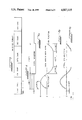
- FIGS. 1A, B, and C represents pulse trains for three arbitrary characters as are transmitted between a control station and a portable remote hand held unit in accordance with the present invention in the electronic data communication system, as shown in FIGS. 6 through 9.
- FIGS. 2A, B, and C illustrate the digital waveforms of the START SYNC, CALIBRATION CHARACTERS, and END SYNC patterns, respectively, of the electronic data communication system of the present invention, as shown in FIGS. 6 through 9.
- FIG. 3 illustrates the transmitted message format sequence of the electronic data communication system of the present invention.
- FIGS. 4A, B, and C illustrate the transformation of a digital waveform into an actual analog signal generated by the D/A converter of the electronic data communication system of the present invention.
- FIG. 5 is a graph of the bandwidth occupied while transmitting in random order all 84 binary values which are available with a 9 bit binary value at 9600 bps.
- FIG. 6 is a block diagram of the principal components of the electronic data communication system of the present invention.
- FIG. 7 is a more detailed block diagram of the portable remote hand held unit portion of the electronic data communication system of present invention.
- FIG. 8 is a more detailed block diagram of the control station of the electronic data communication system of the present invention.
- an adaptive pulse width modem which under the control of software, encodes ASCII characters into a 9 bit binary pattern of logic 1 and logic 0 states.
- a logic 1 state in a given bit position indicates a wide pulse is to be transmitted and a logic 0 state in a given bit position indicates a narrow pulse is to be transmitted.
- Each encoded character consists of an odd number of bits (9), with the pattern transmitted for each character always starting with a positive polarity pulse and always ending with a positive polarity pulse.
- the sum of all logic 1 and all logic 0 positive pulse widths for a given character should equal the sum of all logic 1 and all logic 0 negative pulse widths for that character, so as to minimize voltage bias shifting from character to character as a data block is transmitted.
- This requirement is taken into account by the encoding scheme of this invention.
- the combination of pulse widths and relative positions of the pulses within the 9 bit pattern is such that the receiver decoding process is self-checking on an individual character basis. Further, a pulse width ratio of 2 to 1 is utilized and the number of unique character combinations is established to minimize the bandwidth required to transmit data at high bit rates.
- the ASCII characters are encoded by the adaptive pulse width modem of this invention, such that each character contains nine bits, three logic 1 (wide) pulses and six logic 0 (narrow) pulses.
- the number of possible combinations of unique characters using this encoding method is 84. Since the standard ASCII character set contains 128 characters, two 84 character tables are established by the software. One character in each table is used to shift between the tables, thereby yielding 166 unique, usable characters, while only 84 unique combinations are actually transmitted. While it is possible that more than two tables could be maintained, the multiple shift characters that would be required to move between the multiple character tables would increase overhead on the RF link and thereby reduce data throughput.
- the numerals 1 through 84 in the first column entitled, "ARBITRARY CHARACTER”, are representative of the 84 unique characters to which any arbitrary ASCII character can be assigned.
- the arbitrary characters 1 through 26 could represent the lower case letters "a” through “z” and the numerals 27-52 represent the upper case letters "A” through “Z”.
- the remaining arbitrary characters would be assigned to the remaining characters of the standard ASCII character set.
- One of the arbitrary positions must be reserved to produce the indication to the system to shift to the second table of 84 unique characters.
- the second table also contains a shift character to instruct the system to go back to the first table. As previously set forth, this results in 83 unique characters that are assigned in each table, for a total of 166.
- the second column entitled, HEX VALUE is a 3 digit hex number representing the 9 bit binary pattern that is transmitted for each arbitrary character.
- the third column sets forth the BINARY VALUE representation of the pulse widths to be transmitted. A logic 1 indicating a wide pulse and a logic 0 indicating a narrow pulse.
- a W indicates a wide pulse and a N indicates a narrow pulse.
- Each logic 1 in the BINARY VALUE column is replaced by a W in the pulse form column and each logic 0 in the BINARY VALUE column is replaced by an N in the pulse form column.
- FIG. 1A shows the pulse train which represents the arbitrary character 1 in TABLE I, which has the hex value 103 and the binary value 100000011.
- the pulse train begins with a wide positive pulse representative of the first logic 1, followed by six alternating negative and positive narrow pulses representing the six logic 0's, followed by negative and positive wide pulses representing the two logic 1's.
- FIG. 1B shows the pulse train which represents the arbitrary character 2 in TABLE I, which has the hex value 043 and the binary value 001000011.
- FIG. 1C shows the pulse train which represents the arbitrary character 33 in TABLE I, which has the hex value 08A and the binary value 010001010. It should be noted that each pulse train begins and ends with a positive pulse, and as previously set forth, each has three wide pulses and 6 narrow pulses.
- the electronic data communication system inserts a narrow negative pulse between successive characters as they are transmitted.
- any ASCII character can be assigned to any one of the 84 character combinations. This will allow custom character assignments for any given pair or system of modems. This feature of the system readily provides for data privacy.
- a sync pattern is provided.
- the sync pattern is a 50% duty cycle pattern of narrow pulse widths.
- the sync duration at the beginning of a message, START SYNC as shown in FIG. 2A, is longer than the sync duration at the end of the message, END SYNC as shown in FIG. 2C.
- END SYNC also contains two trailing wide pulses, which further distinguish END SYNC from START SYNC.
- the decoding process should be as fault tolerant of pulse width distortion as possible.
- Most decoding schemes compare pulse widths against fixed absolute values.
- the scheme provided by this invention measures the actual pulse widths of known calibration characters transmitted at the beginning of the message and calculates a set point value against which the following pulse widths are compared. The measurement of the calibration characters allows the system to adapt to transmitter, media, and receiver distortion. Hence, the name adaptive pulse width modem is used in the description of this invention.
- two calibration characters are selected to represent the typical profile of a radio receiver electronic distortion.
- two set points one for positive polarity and one for negative polarity pulses, are dynamically determined from the following four measured conditions:
- the electronic data communication system of this invention provides total message integrity, by attaching to the end of a transmitted message a BCC (block character check) which is checked by the receiver.
- the block character check which is transmitted as wide and narrow pulses represents a checksum which is derived from and is representative of all of the data characters transmitted in one message.
- the receiving unit generates another block character check formed of wide and narrow pulses which represents a checksum derived from and representative of all of the data characters received by the receiver.
- the checksum transmitted to the receiver is compared with that generated by the receiver so as to determine the integrity of the data transmission.
- FIG. 3 illustrates the actual message format and the sequence of sync, calibration characters, data, and BCC.
- the pulse width transmission system of this invention through the use of character encoding, sync patterns, and arbitrary ASCII character assignment to encoded bit patterns provides data security.
- Standard commercial receiver equipment cannot receive the transmissions of this invention and provide an understandable data output to the operator of the receiver equipment. While specialized equipment, such as digital storage devices, and deliberate efforts to decipher the code might result in the recovery of understandable data, this would require the expertise of a technical expert and could not be accomplished by the average lay person.
- the adaptive pulse width modem is designed to be used with a radio that allows a direct modulation input to the transmitter final output stage.
- the microphone limiter circuit is bypassed to allow data transfer at a faster bit rate and with lower distortion.
- typical bit rates are 4800 to 9600 bps.
- the amplitude of narrow pulses tend to be attenuated when compared to wide pulses. Since the amplitudes of the D/A converter is controllable by software, the amplitude of the wide pulses are pre-compensated prior to transmission a shown in FIG. 3C. This results in the reception of normalized pulse amplitudes at the receiver and further enhances the decoding of characters.
- an electronic data communication system 10 comprises a host computer 12, a control station 14, and a portable remote hand held unit 16 linked by a RF communication represented by the antenna 18 and 20, which utilizes the preferred encoding and decoding system of this invention as shown.
- the input to the portable remote hand held unit 16 may be data generated by a bar code reader or data entered on a keyboard, which data is then transmitted through the RF link between the antennas 18 and 20 to the control station 14 wherein the data is converted into signals usable by the host computer 12.
- the more detailed block diagram of FIG. 7 shows the principal components of the portable remote hand held unit 16.
- the portable remote hand held unit includes a central processing unit 22 which performs the function of processing and manipulating data received from various elements of the system, and then provides the manipulated and processed data to other components of the system.
- the central processing unit 22 is a microprocessor commercially available from a variety of manufacturers.
- Connected to and controlling the operation of the central processing unit 22 is a program memory 24.
- the program memory 24 is provided for storing various types of data necessary for controlling the operation of the system.
- the program memory 24 includes a commercially available memory chip that provides for the electronic storage of a large quantity of data in a very small package.
- the memory chip utilized in the program memory 24 may be either a programable read only memory “PROM” or a read only memory “ROM” specifically designed to control the operation of the system.
- Data is provided to the central processing unit by entry through a keyboard 26 or through an electronic interface 28 from other data sources as will hereinafter be explained.
- Data which has been provided to the central processing unit 22 and processed thereby is thereafter stored in a data memory unit 30.
- the principal component of the data memory unit is a commercially available electronic chip which provides a large data storage capacity in a very small package. Should the amount of data to be processed by the remote hand held unit exceed the capacity of the data memory unit 30, an expansion memory 32 may be provided for the purposes of supplementing the memory capacity.
- the data being processed by the central processing unit 22 may be observed on a display unit 34, such as, but not limited to a liquid crystal display of the type which is commercially available.
- the electronic interface unit 28 receives data from one or more sources, which is to be provided to the central processing unit, and in turn receives data from the central processing unit for transmission to a radio link microprocessor modulator 36.
- One source of input to the interface 28 may be a bar code reader, which is connected through a bar code reader interface 38 to the electronic interface 28.
- a standard RS-232 interface is provided to provide for the passing of information through the interface 28 to the central processing unit 22 from a variety of other sources.
- the data which has been passed on to the central processing unit from the bar code reader interface 38 or from the RS-232 interface 40 through the interface 28 is, after processing by the central processing unit 22, retransmitted through the interface 28 to the radio link microprocessor modulator 36.
- the converter 44 in turn provides an analog signal to the radio modulator 46, which generates a RF signal for transmission through antennas, such as shown at 20 in FIG. 6, for ultimate reception by the antenna 18 of the control station 14.
- Data may also be transmitted from the control station 14 to the portable remote hand held unit 16.
- the RF signal received by the antenna 20 from the radiating antenna 18 is processed by the radio modulator to provide a signal to a received data comparator 48, which in turn provides a digital signal to the radio link microprocessor modulator 36 for decoding, processing, and transmission through the interface 28 to the central processing unit 22.
- FIG. 8 depicts in a block diagram from the principal components of the control station 14.
- the principal components of the control station 14 are the same as those of the portable remote hand held unit 16, as shown in FIG. 7.
- Those components of the control station 14, as shown in FIG. 8, which are essentially the same as those of the portable remote hand held unit 16, shown in FIG. 7, are identified by the same numeral.
- the components may perform the same function, they may be and in some cases usually are provided in a different physical form. For instance, the compactness of the unit is more important in the portable remote hand held unit 16, than in the control station 14.
- a panel of option switches 50 is provided. The user positions the switches to select the desired optional configurations through the central processing unit 22.
- a larger display 52 is provided rather than the small display 34 of the hand held unit.
- the front panel display 52 may utilize various display technologies of the same size or greater size than that of in the hand held unit.
- each encoded character consisted of an odd number of bits, with the binary value always starting with a positive polarity pulse and always ending with a positive polarity pulse with a narrow negative polarity pulse being generated by the pulse generating means for transmission between each of the binary values or unique pulse forms.
- the pulse generating means includes a means for generating the complement a binary value or unique pulse form, such that a unique pulse form and the complement of a unique pulse form may be alternately transmitted.
- the generation of the complement of a unique pulse form makes it unnecessary to generate and provide a narrow negative polarity pulse between each of the unique pulse forms.
Landscapes
- Engineering & Computer Science (AREA)
- Theoretical Computer Science (AREA)
- Physics & Mathematics (AREA)
- Spectroscopy & Molecular Physics (AREA)
- Computer Networks & Wireless Communication (AREA)
- Signal Processing (AREA)
- Dc Digital Transmission (AREA)
Priority Applications (4)
| Application Number | Priority Date | Filing Date | Title |
|---|---|---|---|
| US07/019,636 US4817115A (en) | 1987-02-27 | 1987-02-27 | Encoding and decoding system for electronic data communication system |
| PCT/US1988/000601 WO1988006819A1 (fr) | 1987-02-27 | 1988-02-26 | Systeme de codage et de decodage pour systemes electroniques de communication de donnees |
| EP19880903499 EP0303691A4 (fr) | 1987-02-27 | 1988-02-26 | Systeme de codage et de decodage pour systemes electroniques de communication de donnees. |
| CA000559982A CA1284193C (fr) | 1987-02-27 | 1988-02-26 | Systeme de codage et de decodage pour systeme electronique de transmission de donnees |
Applications Claiming Priority (1)
| Application Number | Priority Date | Filing Date | Title |
|---|---|---|---|
| US07/019,636 US4817115A (en) | 1987-02-27 | 1987-02-27 | Encoding and decoding system for electronic data communication system |
Publications (1)
| Publication Number | Publication Date |
|---|---|
| US4817115A true US4817115A (en) | 1989-03-28 |
Family
ID=21794239
Family Applications (1)
| Application Number | Title | Priority Date | Filing Date |
|---|---|---|---|
| US07/019,636 Expired - Lifetime US4817115A (en) | 1987-02-27 | 1987-02-27 | Encoding and decoding system for electronic data communication system |
Country Status (4)
| Country | Link |
|---|---|
| US (1) | US4817115A (fr) |
| EP (1) | EP0303691A4 (fr) |
| CA (1) | CA1284193C (fr) |
| WO (1) | WO1988006819A1 (fr) |
Cited By (48)
| Publication number | Priority date | Publication date | Assignee | Title |
|---|---|---|---|---|
| DE4015854A1 (de) * | 1990-05-17 | 1991-11-21 | Ako Werke Gmbh & Co | Pulsbreiten-modulationsschaltung |
| US5218187A (en) * | 1990-01-18 | 1993-06-08 | Norand Corporation | Hand-held data capture system with interchangeable modules |
| US5331136A (en) * | 1990-01-18 | 1994-07-19 | Norand Corporation | Hand-held data capture system with interchangeable modules |
| US5623258A (en) * | 1993-01-05 | 1997-04-22 | Dorfman; Bertrand | Multi-station data capture system |
| US5675609A (en) * | 1995-05-26 | 1997-10-07 | Dakota Research, Inc. | Sinusoidal pulse and pulse train signaling apparatus |
| US5694418A (en) * | 1995-06-13 | 1997-12-02 | Ncr Corporation | System and method for determining EPL message transmission retries |
| US5696790A (en) * | 1995-10-04 | 1997-12-09 | Tut Systems, Inc. | Method and apparatus for time dependent data transmission |
| US5717688A (en) * | 1993-06-25 | 1998-02-10 | Netwave Technologies Limited | Wireless local area network with roaming indicating multiple communication ranges |
| US5724357A (en) * | 1992-01-28 | 1998-03-03 | Fleetwood Group, Inc. | Remote response system and data transfer protocol |
| WO1999013576A1 (fr) * | 1997-09-08 | 1999-03-18 | Tut Systems, Inc. | Procede et appareil de codage et decodage d'une sequence binaire en vue de sa transmission sur les cables du service telephonique traditionnel |
| US5963539A (en) * | 1997-09-08 | 1999-10-05 | Tut Systems, Inc. | Method and apparatus for detecting collisions on a network |
| US5963194A (en) * | 1993-11-25 | 1999-10-05 | Alps Electric Co. Ltd. | Apparatus for inclination detection and input apparatus using this apparatus |
| US6021119A (en) * | 1994-06-24 | 2000-02-01 | Fleetwood Group, Inc. | Multiple site interactive response system |
| US6102295A (en) * | 1998-01-14 | 2000-08-15 | Intermec Ip Corp. | Method and apparatus for decoding symbols by declaring erasures of element characteristics |
| US6431451B1 (en) | 1991-02-25 | 2002-08-13 | Intermec Ip Corp. | Hand-held data capture system with interchangeable modules |
| US20020190770A1 (en) * | 1999-06-28 | 2002-12-19 | Broadcom Corporation | Current -controlled CMOS circuit using higher voltage supply in low voltage CMOS process |
| US20030001646A1 (en) * | 1999-06-28 | 2003-01-02 | Broadcom Corporation | Current-controlled CMOS logic family |
| US20030067337A1 (en) * | 1999-06-28 | 2003-04-10 | Broadcom Corporation | Current-controlled CMOS circuit using higher voltage supply in low voltage CMOS process |
| US20030122603A1 (en) * | 2000-02-24 | 2003-07-03 | Broadcom Corporation | Current-controlled CMOS circuits with inductive broadbanding |
| US6665000B1 (en) | 1998-11-13 | 2003-12-16 | Fleetwood Group, Inc. | Remote site interactive system |
| US6678321B1 (en) | 1998-09-15 | 2004-01-13 | Tut Systems, Inc. | Method and apparatus for transmitting and receiving a symbol over pots wiring using a multi-cycle waveform |
| US20040017824A1 (en) * | 1989-04-14 | 2004-01-29 | Koenck Steven E. | Modular, portable data processing terminal for use in a radio frequency communication network |
| US20040018851A1 (en) * | 1990-01-18 | 2004-01-29 | Koenck Steven E. | Modular, portable data processing terminal for use in a radio frequency communication network |
| US20040056717A1 (en) * | 2001-10-25 | 2004-03-25 | Broadcom Corporation | Current-controlled CMOS wideband data amplifier circuits |
| US6735217B1 (en) | 1998-09-15 | 2004-05-11 | Tut Systems, Inc. | Method and apparatus for detecting collisions on a network using multi-cycle waveform pulses |
| US6771774B1 (en) | 1999-12-02 | 2004-08-03 | Tut Systems, Inc. | Filter arrangement for shaping a pulse propagated over pots wiring, and a method of manufacturing the same |
| US20040207040A1 (en) * | 2001-05-17 | 2004-10-21 | Broadcom Corporation | Layout technique for C3MOS inductive broadbanding |
| US20040217777A1 (en) * | 1999-06-28 | 2004-11-04 | Armond Hairapetian | Universal single-ended parallel bus |
| US20050087603A1 (en) * | 1988-01-14 | 2005-04-28 | Koenck Steven E. | Hand-held data capture system with interchangeable modules |
| US20050094784A1 (en) * | 1999-10-28 | 2005-05-05 | Lightwaves Systems Inc. | System and method of using variable pulses for symbology |
| US20060015655A1 (en) * | 2002-08-30 | 2006-01-19 | Zur Uri E | Method and system for supporting read operations with CRC for iSCSI and iSCSI chimney |
| US20070024369A1 (en) * | 2005-07-29 | 2007-02-01 | Jun Cao | Current-controlled CMOS (C3MOS) wideband input data amplifier for reduced differential and common-mode reflection |
| US20070025435A1 (en) * | 2005-07-29 | 2007-02-01 | Jun Cao | Current-controlled CMOS (C3MOS) fully differential integrated wideband amplifier/equalizer with adjustable gain and frequency response without additional power or loading |
| US20070052467A1 (en) * | 2005-09-06 | 2007-03-08 | Jun Cao | Current-controlled CMOS (C3MOS) fully differential integrated delay cell with variable delay and high bandwidth |
| US20070237163A1 (en) * | 2001-07-23 | 2007-10-11 | Broadcom Corporation | Multiple virtual channels for use in network devices |
| US20080025315A1 (en) * | 2002-03-08 | 2008-01-31 | Broadcom Corporation | System and method for identifying upper layer protocol message boundaries |
| US20080095182A1 (en) * | 2002-08-30 | 2008-04-24 | Uri Elzur | System and method for tcp/ip offload independent of bandwidth delay product |
| US20080151922A1 (en) * | 2002-08-30 | 2008-06-26 | Uri Elzur | System and method for tcp offload |
| US20080298369A1 (en) * | 2002-08-30 | 2008-12-04 | Uri Elzur | System and method for handling out-of-order frames |
| US20090074408A1 (en) * | 1997-01-23 | 2009-03-19 | Broadcom Corporation | Fibre channel arbitrated loop bufferless switch circuitry to increase bandwidth without significant increase in cost |
| US20090254647A1 (en) * | 2002-08-29 | 2009-10-08 | Uri Elzur | System and method for network interfacing |
| US7853254B2 (en) | 1993-08-31 | 2010-12-14 | Broadcom Corp. | Modular, portable data processing terminal for use in a radio frequency communication network |
| EP2571216A1 (fr) * | 2011-09-16 | 2013-03-20 | Gemalto SA | Procédé de transmission d'une trame de données en utilisant une modulation à largeurs d'impulsions adaptive |
| USH2274H1 (en) * | 2009-01-30 | 2013-05-07 | The United States Of America, As Represented By The Secretary Of The Navy | Variable pulse width encoding for information transmission |
| US8798091B2 (en) | 1998-11-19 | 2014-08-05 | Broadcom Corporation | Fibre channel arbitrated loop bufferless switch circuitry to increase bandwidth without significant increase in cost |
| US20160065398A1 (en) * | 2014-08-27 | 2016-03-03 | International Recitifer Corporation | Communication over a voltage isolation barrier |
| US9390360B1 (en) * | 2015-03-26 | 2016-07-12 | Abomem Technology Corp. | NFC payment moudle and controlling method thereof |
| KR20170044164A (ko) * | 2014-09-05 | 2017-04-24 | 쿠앙치 인텔리전트 포토닉 테크놀로지 리미티드 | 신호의 코딩/디코딩 방법, 장치 및 시스템 |
Families Citing this family (2)
| Publication number | Priority date | Publication date | Assignee | Title |
|---|---|---|---|---|
| US4897854A (en) * | 1989-02-24 | 1990-01-30 | General Instrument Corporation | Alternate pulse inversion encoding scheme for serial data transmission |
| WO2016034033A1 (fr) * | 2014-09-05 | 2016-03-10 | 深圳光启智能光子技术有限公司 | Procédés de codage et de décodage de signal optique, et dispositif |
Citations (13)
| Publication number | Priority date | Publication date | Assignee | Title |
|---|---|---|---|---|
| US3439327A (en) * | 1964-07-23 | 1969-04-15 | Sagem | Systems for protection against errors in transmission |
| US3528057A (en) * | 1965-12-03 | 1970-09-08 | Nederlanden Staat | System for transmitting digital traffic signals |
| US4001728A (en) * | 1974-02-27 | 1977-01-04 | The United States Of America As Represented By The Secretary Of The Navy | Digital method of pulse width modulation |
| US4066841A (en) * | 1974-01-25 | 1978-01-03 | Serck Industries Limited | Data transmitting systems |
| US4282601A (en) * | 1979-03-02 | 1981-08-04 | Burroughs Corporation | Three level data transmission system having means for seeking a constant average value for the transmitted signals |
| US4373152A (en) * | 1980-12-22 | 1983-02-08 | Honeywell Information Systems Inc. | Binary to one out of four converter |
| US4408189A (en) * | 1981-05-18 | 1983-10-04 | Northern Telecom Limited | Method and apparatus for code conversion of binary to multilevel signals |
| US4419757A (en) * | 1981-03-16 | 1983-12-06 | Bell Telephone Laboratories, Incorporated | Transformerless bipolar converter |
| US4426667A (en) * | 1978-05-17 | 1984-01-17 | Savin Corporation | Pulse width modulation system |
| US4489417A (en) * | 1982-11-24 | 1984-12-18 | International Business Machines Corporation | Multi-level communication circuitry for communicating digital signals between integrated circuits |
| US4497060A (en) * | 1982-12-08 | 1985-01-29 | Lockheed Electronics Co., Inc. | Self-clocking binary receiver |
| US4567601A (en) * | 1982-07-19 | 1986-01-28 | British Telecommunications | Three-to-two level digital signal conversions and vice versa |
| US4599723A (en) * | 1984-02-14 | 1986-07-08 | Pulse Electronics, Inc. | Method of encoding data for serial transmission |
Family Cites Families (4)
| Publication number | Priority date | Publication date | Assignee | Title |
|---|---|---|---|---|
| US4327441A (en) * | 1980-03-31 | 1982-04-27 | Texas Instruments Incorporated | Method and apparatus for synchronizing and calibrating a receiver to a pulse width modulation transmitter |
| FR2495858A1 (fr) * | 1980-12-05 | 1982-06-11 | Thomson Csf | Procede de transcodage parallele serie d'un train numerique parallele et dispositif de transmission de signaux video numerises mettant en oeuvre un tel procede |
| US4393501A (en) * | 1981-02-26 | 1983-07-12 | General Electric Company | Line protocol for communication system |
| DE3432153A1 (de) * | 1984-08-31 | 1986-03-13 | Josef Dipl.-Ing. Dirr (FH), 8000 München | Verfahren fuer die codierung digitaler signale bezw. alphabete, insbesondere fuer die uebertragung ueber anschluss- und/oder verbindungsleitungen bei telegrafie- und datenuebertragungssystemen und bei tastwahl in vermittlungsanlagen |
-
1987
- 1987-02-27 US US07/019,636 patent/US4817115A/en not_active Expired - Lifetime
-
1988
- 1988-02-26 WO PCT/US1988/000601 patent/WO1988006819A1/fr not_active Ceased
- 1988-02-26 CA CA000559982A patent/CA1284193C/fr not_active Expired - Lifetime
- 1988-02-26 EP EP19880903499 patent/EP0303691A4/fr not_active Withdrawn
Patent Citations (13)
| Publication number | Priority date | Publication date | Assignee | Title |
|---|---|---|---|---|
| US3439327A (en) * | 1964-07-23 | 1969-04-15 | Sagem | Systems for protection against errors in transmission |
| US3528057A (en) * | 1965-12-03 | 1970-09-08 | Nederlanden Staat | System for transmitting digital traffic signals |
| US4066841A (en) * | 1974-01-25 | 1978-01-03 | Serck Industries Limited | Data transmitting systems |
| US4001728A (en) * | 1974-02-27 | 1977-01-04 | The United States Of America As Represented By The Secretary Of The Navy | Digital method of pulse width modulation |
| US4426667A (en) * | 1978-05-17 | 1984-01-17 | Savin Corporation | Pulse width modulation system |
| US4282601A (en) * | 1979-03-02 | 1981-08-04 | Burroughs Corporation | Three level data transmission system having means for seeking a constant average value for the transmitted signals |
| US4373152A (en) * | 1980-12-22 | 1983-02-08 | Honeywell Information Systems Inc. | Binary to one out of four converter |
| US4419757A (en) * | 1981-03-16 | 1983-12-06 | Bell Telephone Laboratories, Incorporated | Transformerless bipolar converter |
| US4408189A (en) * | 1981-05-18 | 1983-10-04 | Northern Telecom Limited | Method and apparatus for code conversion of binary to multilevel signals |
| US4567601A (en) * | 1982-07-19 | 1986-01-28 | British Telecommunications | Three-to-two level digital signal conversions and vice versa |
| US4489417A (en) * | 1982-11-24 | 1984-12-18 | International Business Machines Corporation | Multi-level communication circuitry for communicating digital signals between integrated circuits |
| US4497060A (en) * | 1982-12-08 | 1985-01-29 | Lockheed Electronics Co., Inc. | Self-clocking binary receiver |
| US4599723A (en) * | 1984-02-14 | 1986-07-08 | Pulse Electronics, Inc. | Method of encoding data for serial transmission |
Cited By (122)
| Publication number | Priority date | Publication date | Assignee | Title |
|---|---|---|---|---|
| US20050087603A1 (en) * | 1988-01-14 | 2005-04-28 | Koenck Steven E. | Hand-held data capture system with interchangeable modules |
| US7712669B2 (en) | 1988-01-14 | 2010-05-11 | Broadcom Corporation | Hand-held data capture system with interchangeable modules |
| US20040017824A1 (en) * | 1989-04-14 | 2004-01-29 | Koenck Steven E. | Modular, portable data processing terminal for use in a radio frequency communication network |
| US7080788B2 (en) | 1989-04-14 | 2006-07-25 | Broadcom Corporation | Modular, portable data processing terminal for use in a radio frequency communication network |
| US5567925A (en) * | 1990-01-18 | 1996-10-22 | Norand Corporation | Hand-held data capture system with interchangeable modules |
| US20040018851A1 (en) * | 1990-01-18 | 2004-01-29 | Koenck Steven E. | Modular, portable data processing terminal for use in a radio frequency communication network |
| US5331136A (en) * | 1990-01-18 | 1994-07-19 | Norand Corporation | Hand-held data capture system with interchangeable modules |
| US5218187A (en) * | 1990-01-18 | 1993-06-08 | Norand Corporation | Hand-held data capture system with interchangeable modules |
| US7383038B2 (en) | 1990-01-18 | 2008-06-03 | Broadcom Corporation | Modular, portable data processing terminal for use in a radio frequency communication network |
| US7757956B2 (en) | 1990-01-18 | 2010-07-20 | Broadcom Corporation | Modular, portable data processing terminal for use in a radio frequency communication network |
| DE4015854A1 (de) * | 1990-05-17 | 1991-11-21 | Ako Werke Gmbh & Co | Pulsbreiten-modulationsschaltung |
| DE4015854C3 (de) * | 1990-05-17 | 2000-01-27 | Ako Werke Gmbh & Co | Pulsbreiten-Modulationsschaltung |
| US6431451B1 (en) | 1991-02-25 | 2002-08-13 | Intermec Ip Corp. | Hand-held data capture system with interchangeable modules |
| US5724357A (en) * | 1992-01-28 | 1998-03-03 | Fleetwood Group, Inc. | Remote response system and data transfer protocol |
| US5623258A (en) * | 1993-01-05 | 1997-04-22 | Dorfman; Bertrand | Multi-station data capture system |
| US5875186A (en) * | 1993-06-25 | 1999-02-23 | Netwave Technologies Limited | Dynamic wireless local area network with interactive communications within the network |
| US5838730A (en) * | 1993-06-25 | 1998-11-17 | Netwave Technologies Limited | Radio transmitter/receiver for wireless local area network |
| US5729680A (en) * | 1993-06-25 | 1998-03-17 | Netwave Technologies Limited | Ad hoc initialization for wireless local area network |
| US5717688A (en) * | 1993-06-25 | 1998-02-10 | Netwave Technologies Limited | Wireless local area network with roaming indicating multiple communication ranges |
| US7992788B2 (en) | 1993-08-31 | 2011-08-09 | Broadcom Corporation | Method used by a communication device for use in a communication channel |
| US20090238319A1 (en) * | 1993-08-31 | 2009-09-24 | Phillip Miller | Modular, portable data processing terminal for use in a radio frequency communication network |
| US7853254B2 (en) | 1993-08-31 | 2010-12-14 | Broadcom Corp. | Modular, portable data processing terminal for use in a radio frequency communication network |
| US7537167B1 (en) | 1993-08-31 | 2009-05-26 | Broadcom Corporation | Modular, portable data processing terminal for use in a radio frequency communication network |
| US20100282852A1 (en) * | 1993-08-31 | 2010-11-11 | Koenck Steven E | Modular, portable data processing terminal for use in a radio frequency communication |
| US5963194A (en) * | 1993-11-25 | 1999-10-05 | Alps Electric Co. Ltd. | Apparatus for inclination detection and input apparatus using this apparatus |
| US6021119A (en) * | 1994-06-24 | 2000-02-01 | Fleetwood Group, Inc. | Multiple site interactive response system |
| US5675609A (en) * | 1995-05-26 | 1997-10-07 | Dakota Research, Inc. | Sinusoidal pulse and pulse train signaling apparatus |
| AU699744B2 (en) * | 1995-06-13 | 1998-12-10 | Ncr Corporation | An electronic price label (EPL) system |
| US5694418A (en) * | 1995-06-13 | 1997-12-02 | Ncr Corporation | System and method for determining EPL message transmission retries |
| US5696790A (en) * | 1995-10-04 | 1997-12-09 | Tut Systems, Inc. | Method and apparatus for time dependent data transmission |
| US8767756B2 (en) | 1997-01-23 | 2014-07-01 | Broadcom Corporation | Fibre channel arbitrated loop bufferless switch circuitry to increase bandwidth without significant increase in cost |
| US20090074408A1 (en) * | 1997-01-23 | 2009-03-19 | Broadcom Corporation | Fibre channel arbitrated loop bufferless switch circuitry to increase bandwidth without significant increase in cost |
| US8774199B2 (en) | 1997-01-23 | 2014-07-08 | Broadcom Corporation | Fibre channel arbitrated loop bufferless switch circuitry to increase bandwidth without significant increase in cost |
| US8750320B2 (en) | 1997-01-23 | 2014-06-10 | Broadcom Corporation | Fibre channel arbitrated loop bufferless switch circuitry to increase bandwidth without significant increase in cost |
| AU746150B2 (en) * | 1997-09-08 | 2002-04-18 | Tut Systems, Inc. | Method and apparatus for encoding and decoding a bit sequence for transmission over pots wiring |
| US5963595A (en) * | 1997-09-08 | 1999-10-05 | Tut Systems, Inc. | Method and apparatus for encoding and decoding a bit sequence for transmission over POTS wiring |
| US6381213B1 (en) | 1997-09-08 | 2002-04-30 | Tut Systems, Inc. | Method and apparatus for detecting collisions on a network |
| US5963539A (en) * | 1997-09-08 | 1999-10-05 | Tut Systems, Inc. | Method and apparatus for detecting collisions on a network |
| WO1999013576A1 (fr) * | 1997-09-08 | 1999-03-18 | Tut Systems, Inc. | Procede et appareil de codage et decodage d'une sequence binaire en vue de sa transmission sur les cables du service telephonique traditionnel |
| US6102295A (en) * | 1998-01-14 | 2000-08-15 | Intermec Ip Corp. | Method and apparatus for decoding symbols by declaring erasures of element characteristics |
| US6678321B1 (en) | 1998-09-15 | 2004-01-13 | Tut Systems, Inc. | Method and apparatus for transmitting and receiving a symbol over pots wiring using a multi-cycle waveform |
| US6735217B1 (en) | 1998-09-15 | 2004-05-11 | Tut Systems, Inc. | Method and apparatus for detecting collisions on a network using multi-cycle waveform pulses |
| US6665000B1 (en) | 1998-11-13 | 2003-12-16 | Fleetwood Group, Inc. | Remote site interactive system |
| US8798091B2 (en) | 1998-11-19 | 2014-08-05 | Broadcom Corporation | Fibre channel arbitrated loop bufferless switch circuitry to increase bandwidth without significant increase in cost |
| US20020190770A1 (en) * | 1999-06-28 | 2002-12-19 | Broadcom Corporation | Current -controlled CMOS circuit using higher voltage supply in low voltage CMOS process |
| US6937080B2 (en) | 1999-06-28 | 2005-08-30 | Broadcom Corporation | Current-controlled CMOS logic family |
| US6982583B2 (en) | 1999-06-28 | 2006-01-03 | Broadcom Corporation | Current-controlled CMOS circuit using higher voltage supply in low voltage CMOS process |
| US9831853B2 (en) | 1999-06-28 | 2017-11-28 | Avago Technologies General Ip (Singapore) Pte. Ltd. | Current-controlled CMOS logic family |
| US20100237921A1 (en) * | 1999-06-28 | 2010-09-23 | Broadcom Corporation | Current-controlled CMOS logic family |
| US20100225355A1 (en) * | 1999-06-28 | 2010-09-09 | Broadcom Corporation | Current-controlled CMOS logic family |
| US10396763B2 (en) | 1999-06-28 | 2019-08-27 | Avago Technologies International Sales Pte. Limited | Current-controlled CMOS logic family |
| US7135889B2 (en) | 1999-06-28 | 2006-11-14 | Broadcom Corporation | Universal single-ended parallel bus |
| US9112487B2 (en) | 1999-06-28 | 2015-08-18 | Broadcom Corporation | Current-controlled CMOS logic family |
| US20040227544A1 (en) * | 1999-06-28 | 2004-11-18 | Guangming Yin | Current-controlled CMOS circuit using higher voltage supply in low voltage CMOS process |
| US8823435B2 (en) | 1999-06-28 | 2014-09-02 | Broadcom Corporation | Current-controlled CMOS logic family |
| US6911855B2 (en) | 1999-06-28 | 2005-06-28 | Broadcom Corporation | Current-controlled CMOS circuit using higher voltage supply in low voltage CMOS process |
| US7724057B2 (en) | 1999-06-28 | 2010-05-25 | Broadcom Corporation | Current-controlled CMOS logic family |
| US20040217777A1 (en) * | 1999-06-28 | 2004-11-04 | Armond Hairapetian | Universal single-ended parallel bus |
| US20030067337A1 (en) * | 1999-06-28 | 2003-04-10 | Broadcom Corporation | Current-controlled CMOS circuit using higher voltage supply in low voltage CMOS process |
| US20030001646A1 (en) * | 1999-06-28 | 2003-01-02 | Broadcom Corporation | Current-controlled CMOS logic family |
| US6900670B2 (en) | 1999-06-28 | 2005-05-31 | Broadcom Corporation | Current-controlled CMOS logic family |
| US8299834B2 (en) | 1999-06-28 | 2012-10-30 | Broadcom Corporation | Current-controlled CMOS logic family |
| US6897697B2 (en) | 1999-06-28 | 2005-05-24 | Broadcom Corporation | Current-controlled CMOS circuit using higher voltage supply in low voltage CMOS process |
| US20090128380A1 (en) * | 1999-06-28 | 2009-05-21 | Broadcom Corporation | Current-controlled CMOS logic family |
| US9077441B2 (en) | 1999-10-28 | 2015-07-07 | Lightwaves Systems, Inc. | System and method of using variable pulses for symbology |
| US7881619B2 (en) * | 1999-10-28 | 2011-02-01 | Lightwaves Systems, Inc. | System and method of using variable pulses for symbology |
| US9350418B2 (en) | 1999-10-28 | 2016-05-24 | Lightwaves Systems, Inc. | System and method of using variable pulses for symbology |
| US20050094784A1 (en) * | 1999-10-28 | 2005-05-05 | Lightwaves Systems Inc. | System and method of using variable pulses for symbology |
| US8768176B2 (en) | 1999-10-28 | 2014-07-01 | Lightwaves Systems, Inc. | System and method of using variable pulses for symbology |
| US20110103461A1 (en) * | 1999-10-28 | 2011-05-05 | Lightwaves Systems, Inc. | System and method of using variable pulses for symbology |
| US6771774B1 (en) | 1999-12-02 | 2004-08-03 | Tut Systems, Inc. | Filter arrangement for shaping a pulse propagated over pots wiring, and a method of manufacturing the same |
| US6909309B2 (en) | 2000-02-24 | 2005-06-21 | Broadcom Corporation | Current-controlled CMOS circuits with inductive broadbanding |
| US7919985B2 (en) | 2000-02-24 | 2011-04-05 | Broadcom Corporation | Current-controlled CMOS circuits with inductive broadbanding |
| US20090140771A1 (en) * | 2000-02-24 | 2009-06-04 | Broadcom Corporation | Current-controlled CMOS circuits with inductive broadbanding |
| US20030122603A1 (en) * | 2000-02-24 | 2003-07-03 | Broadcom Corporation | Current-controlled CMOS circuits with inductive broadbanding |
| US20040207040A1 (en) * | 2001-05-17 | 2004-10-21 | Broadcom Corporation | Layout technique for C3MOS inductive broadbanding |
| US7132727B2 (en) | 2001-05-17 | 2006-11-07 | Broadcom Corporation | Layout technique for C3MOS inductive broadbanding |
| US6864558B2 (en) | 2001-05-17 | 2005-03-08 | Broadcom Corporation | Layout technique for C3MOS inductive broadbanding |
| US20110110236A1 (en) * | 2001-07-23 | 2011-05-12 | Shiri Kadambi | Multiple Logical Channels for Use in Network Devices |
| US20070237163A1 (en) * | 2001-07-23 | 2007-10-11 | Broadcom Corporation | Multiple virtual channels for use in network devices |
| US8116203B2 (en) | 2001-07-23 | 2012-02-14 | Broadcom Corporation | Multiple virtual channels for use in network devices |
| US9036643B2 (en) | 2001-07-23 | 2015-05-19 | Broadcom Corporation | Multiple logical channels for use in network devices |
| US8493857B2 (en) | 2001-07-23 | 2013-07-23 | Broadcom Corporation | Multiple logical channels for use in network devices |
| US7109799B2 (en) | 2001-10-25 | 2006-09-19 | Broadcom Corporation | Current-controlled CMOS wideband data amplifier circuits |
| US20040056717A1 (en) * | 2001-10-25 | 2004-03-25 | Broadcom Corporation | Current-controlled CMOS wideband data amplifier circuits |
| US20080025315A1 (en) * | 2002-03-08 | 2008-01-31 | Broadcom Corporation | System and method for identifying upper layer protocol message boundaries |
| US20100223540A1 (en) * | 2002-03-08 | 2010-09-02 | Uri Elzur | System and method for identifying upper layer protocol message boundaries |
| US8451863B2 (en) | 2002-03-08 | 2013-05-28 | Broadcom Corporation | System and method for identifying upper layer protocol message boundaries |
| US20100220729A1 (en) * | 2002-03-08 | 2010-09-02 | Uri Elzur | System and method for identifying upper layer protocol message boundaries |
| US8135016B2 (en) | 2002-03-08 | 2012-03-13 | Broadcom Corporation | System and method for identifying upper layer protocol message boundaries |
| US8345689B2 (en) | 2002-03-08 | 2013-01-01 | Broadcom Corporation | System and method for identifying upper layer protocol message boundaries |
| US8958440B2 (en) | 2002-03-08 | 2015-02-17 | Broadcom Corporation | System and method for identifying upper layer protocol message boundaries |
| US7934021B2 (en) | 2002-08-29 | 2011-04-26 | Broadcom Corporation | System and method for network interfacing |
| US20090254647A1 (en) * | 2002-08-29 | 2009-10-08 | Uri Elzur | System and method for network interfacing |
| US20100142534A1 (en) * | 2002-08-30 | 2010-06-10 | Uri Elzur | System and method for handling out-of-order frames |
| US7912064B2 (en) | 2002-08-30 | 2011-03-22 | Broadcom Corporation | System and method for handling out-of-order frames |
| US8402142B2 (en) | 2002-08-30 | 2013-03-19 | Broadcom Corporation | System and method for TCP/IP offload independent of bandwidth delay product |
| US20060015655A1 (en) * | 2002-08-30 | 2006-01-19 | Zur Uri E | Method and system for supporting read operations with CRC for iSCSI and iSCSI chimney |
| US20080298369A1 (en) * | 2002-08-30 | 2008-12-04 | Uri Elzur | System and method for handling out-of-order frames |
| US7849208B2 (en) | 2002-08-30 | 2010-12-07 | Broadcom Corporation | System and method for TCP offload |
| US7929540B2 (en) | 2002-08-30 | 2011-04-19 | Broadcom Corporation | System and method for handling out-of-order frames |
| US8180928B2 (en) | 2002-08-30 | 2012-05-15 | Broadcom Corporation | Method and system for supporting read operations with CRC for iSCSI and iSCSI chimney |
| US20100250783A1 (en) * | 2002-08-30 | 2010-09-30 | Uri Elzur | System and method for tcp/ip offload independent of bandwidth delay product |
| US20080151922A1 (en) * | 2002-08-30 | 2008-06-26 | Uri Elzur | System and method for tcp offload |
| US8677010B2 (en) | 2002-08-30 | 2014-03-18 | Broadcom Corporation | System and method for TCP offload |
| US20080095182A1 (en) * | 2002-08-30 | 2008-04-24 | Uri Elzur | System and method for tcp/ip offload independent of bandwidth delay product |
| US20110040891A1 (en) * | 2002-08-30 | 2011-02-17 | Uri Elzur | System and Method for TCP Offload |
| US8549152B2 (en) | 2002-08-30 | 2013-10-01 | Broadcom Corporation | System and method for TCP/IP offload independent of bandwidth delay product |
| US7362174B2 (en) | 2005-07-29 | 2008-04-22 | Broadcom Corporation | Current-controlled CMOS (C3MOS) wideband input data amplifier for reduced differential and common-mode reflection |
| US7598811B2 (en) | 2005-07-29 | 2009-10-06 | Broadcom Corporation | Current-controlled CMOS (C3MOS) fully differential integrated wideband amplifier/equalizer with adjustable gain and frequency response without additional power or loading |
| US20070025435A1 (en) * | 2005-07-29 | 2007-02-01 | Jun Cao | Current-controlled CMOS (C3MOS) fully differential integrated wideband amplifier/equalizer with adjustable gain and frequency response without additional power or loading |
| US20070024369A1 (en) * | 2005-07-29 | 2007-02-01 | Jun Cao | Current-controlled CMOS (C3MOS) wideband input data amplifier for reduced differential and common-mode reflection |
| US20070052467A1 (en) * | 2005-09-06 | 2007-03-08 | Jun Cao | Current-controlled CMOS (C3MOS) fully differential integrated delay cell with variable delay and high bandwidth |
| US7598788B2 (en) | 2005-09-06 | 2009-10-06 | Broadcom Corporation | Current-controlled CMOS (C3MOS) fully differential integrated delay cell with variable delay and high bandwidth |
| US8891355B1 (en) | 2009-01-30 | 2014-11-18 | The United States Of America As Represented By The Secretary Of The Navy | Information transmitter with variable pulse width encoding |
| USH2274H1 (en) * | 2009-01-30 | 2013-05-07 | The United States Of America, As Represented By The Secretary Of The Navy | Variable pulse width encoding for information transmission |
| WO2013037599A1 (fr) * | 2011-09-16 | 2013-03-21 | Gemalto S.A. | Procédé pour la transmission d'une trame de données au moyen d'une modulation de largeur d'impulsions adaptative |
| EP2571216A1 (fr) * | 2011-09-16 | 2013-03-20 | Gemalto SA | Procédé de transmission d'une trame de données en utilisant une modulation à largeurs d'impulsions adaptive |
| US20160065398A1 (en) * | 2014-08-27 | 2016-03-03 | International Recitifer Corporation | Communication over a voltage isolation barrier |
| US9685923B2 (en) * | 2014-08-27 | 2017-06-20 | Infineon Technologies Americas Corp. | Communication over a voltage isolation barrier |
| KR20170044164A (ko) * | 2014-09-05 | 2017-04-24 | 쿠앙치 인텔리전트 포토닉 테크놀로지 리미티드 | 신호의 코딩/디코딩 방법, 장치 및 시스템 |
| US9390360B1 (en) * | 2015-03-26 | 2016-07-12 | Abomem Technology Corp. | NFC payment moudle and controlling method thereof |
Also Published As
| Publication number | Publication date |
|---|---|
| EP0303691A1 (fr) | 1989-02-22 |
| EP0303691A4 (fr) | 1990-02-22 |
| WO1988006819A1 (fr) | 1988-09-07 |
| CA1284193C (fr) | 1991-05-14 |
Similar Documents
| Publication | Publication Date | Title |
|---|---|---|
| US4817115A (en) | Encoding and decoding system for electronic data communication system | |
| JP3153084B2 (ja) | パルス変調方法 | |
| AU599613B2 (en) | Radio communication receiver with apparatus for altering bit rate of the receiver | |
| CA2473880C (fr) | Systeme de communications a etalement de spectre a saut de frequence | |
| US4479215A (en) | Power-line carrier communications system with interference avoidance capability | |
| JP3778969B2 (ja) | スペクトラム拡散コードパルス位置変調のための方法及び装置 | |
| US4642632A (en) | Digital paging system having bit rate switching means and digital paging receiver therefor | |
| US3760277A (en) | Coding and decoding system with multi-level format | |
| US5168510A (en) | Spread spectrum-time diversity communications systems and transceivers for multidrop area networks | |
| US3988676A (en) | Coding and decoding system with multi-level format | |
| US4390986A (en) | Digital subscriber communication system | |
| GB1575037A (en) | Data transmission | |
| CN1044370A (zh) | 信令发射机的主动控制 | |
| US4320522A (en) | Programmable frequency and signalling format tone frequency encoder/decoder circuit | |
| US4613973A (en) | Digital data decoder and method | |
| US3457510A (en) | Modified duobinary data transmission | |
| US9485124B2 (en) | Method and apparatus for multiple bit encoding | |
| US4015204A (en) | Method of telecommunications | |
| Shannon | General treatment of the problem of coding | |
| US4445175A (en) | Supervisory remote control system employing pseudorandom sequence | |
| US4276651A (en) | Clock circuitry for a data communication system | |
| US6954496B2 (en) | Method for transmitting data from an interrogating device to portable objects | |
| RU211269U1 (ru) | Устройство адаптивной передачи фазомодулированных цифровых сигналов | |
| Long | Radio telemetry | |
| RU2210192C2 (ru) | Способ модуляции цифрового сигнала для передачи данных по узкополосным каналам электросвязи |
Legal Events
| Date | Code | Title | Description |
|---|---|---|---|
| AS | Assignment |
Owner name: TELXON CORPORATION, 3330 WEST MARKET ST. AKRON, OH Free format text: ASSIGNMENT OF ASSIGNORS INTEREST.;ASSIGNORS:CAMPO, JAMES A.;SUTHERLAND, JEFFREY W.;KRILL, CARL E. III;REEL/FRAME:004735/0524;SIGNING DATES FROM 19870615 TO 19870622 |
|
| STCF | Information on status: patent grant |
Free format text: PATENTED CASE |
|
| FEPP | Fee payment procedure |
Free format text: PAYOR NUMBER ASSIGNED (ORIGINAL EVENT CODE: ASPN); ENTITY STATUS OF PATENT OWNER: LARGE ENTITY |
|
| CC | Certificate of correction | ||
| FPAY | Fee payment |
Year of fee payment: 4 |
|
| AS | Assignment |
Owner name: BANK OF NEW YORK COMMERCIAL CORPORATION, THE, AS A Free format text: SECURITY INTEREST;ASSIGNOR:TELXON CORPORATION;REEL/FRAME:007012/0372 Effective date: 19931020 |
|
| AS | Assignment |
Owner name: TELXON CORPORATION, OHIO Free format text: RELEASE BY SECURED PARTY;ASSIGNOR:BANK OF NEW YORK COMMERICAL CORPORATION, AS AGENT, THE, BY: DANIEL J. MURRAY, VP;REEL/FRAME:007919/0172 Effective date: 19960308 |
|
| FPAY | Fee payment |
Year of fee payment: 8 |
|
| AS | Assignment |
Owner name: BANK ONE, NA, OHIO Free format text: ASSIGNMENT OF ASSIGNORS INTEREST;ASSIGNOR:TELXON CORPORATION, A DELAWARE CORPORATION;REEL/FRAME:009866/0723 Effective date: 19990326 |
|
| AS | Assignment |
Owner name: FOOTHILL CAPITAL CORPORATION AS AGENT, CALIFORNIA Free format text: SECURITY INTEREST;ASSIGNOR:TELXON CORPORATION;REEL/FRAME:010216/0081 Effective date: 19990826 Owner name: TELXON CORPORATION, OHIO Free format text: RELEASE OF SECURITY INTEREST;ASSIGNOR:BANK ONE, NA;REEL/FRAME:010216/0050 Effective date: 19990830 |
|
| FEPP | Fee payment procedure |
Free format text: PAYOR NUMBER ASSIGNED (ORIGINAL EVENT CODE: ASPN); ENTITY STATUS OF PATENT OWNER: LARGE ENTITY Free format text: PAYER NUMBER DE-ASSIGNED (ORIGINAL EVENT CODE: RMPN); ENTITY STATUS OF PATENT OWNER: LARGE ENTITY |
|
| FPAY | Fee payment |
Year of fee payment: 12 |
|
| AS | Assignment |
Owner name: SYMBOL TECHNOLOGIES, INC., NEW YORK Free format text: ASSIGNMENT OF ASSIGNORS INTEREST;ASSIGNOR:TELXON CORPORATION;REEL/FRAME:012795/0070 Effective date: 20020327 |
|
| AS | Assignment |
Owner name: JPMORGAN CHASE BANK, N.A., NEW YORK Free format text: SECURITY INTEREST;ASSIGNOR:SYMBOL TECHNOLOGIES, INC.;REEL/FRAME:016116/0203 Effective date: 20041229 |
|
| AS | Assignment |
Owner name: TELXON CORPORATION, OHIO Free format text: RELEASE OF SECURITY AGREEMENT;ASSIGNOR:WELLS FARGO FOOTHILL, INC. (FORMERLY FOOTHILL CAPITAL CORPORATION);REEL/FRAME:016621/0303 Effective date: 20050716 |