US4817792A - Individual container that can be assembled to a multiple storage container - Google Patents
Individual container that can be assembled to a multiple storage container Download PDFInfo
- Publication number
- US4817792A US4817792A US07/220,580 US22058088A US4817792A US 4817792 A US4817792 A US 4817792A US 22058088 A US22058088 A US 22058088A US 4817792 A US4817792 A US 4817792A
- Authority
- US
- United States
- Prior art keywords
- individual
- container
- individual container
- assembled
- multiple storage
- Prior art date
- Legal status (The legal status is an assumption and is not a legal conclusion. Google has not performed a legal analysis and makes no representation as to the accuracy of the status listed.)
- Expired - Fee Related
Links
- 238000003860 storage Methods 0.000 title claims abstract description 29
- 210000002105 tongue Anatomy 0.000 claims description 18
- 230000009471 action Effects 0.000 claims description 3
- 230000000694 effects Effects 0.000 claims description 3
- 230000001681 protective effect Effects 0.000 claims description 2
- 230000007704 transition Effects 0.000 claims description 2
- 239000000969 carrier Substances 0.000 claims 1
- 230000000295 complement effect Effects 0.000 claims 1
- 238000012856 packing Methods 0.000 abstract description 8
- 238000013500 data storage Methods 0.000 abstract 1
- 239000000463 material Substances 0.000 description 6
- 230000007246 mechanism Effects 0.000 description 5
- 238000004519 manufacturing process Methods 0.000 description 4
- 230000000717 retained effect Effects 0.000 description 4
- 238000011161 development Methods 0.000 description 3
- 230000018109 developmental process Effects 0.000 description 3
- 238000001746 injection moulding Methods 0.000 description 3
- 238000000034 method Methods 0.000 description 3
- 238000013461 design Methods 0.000 description 2
- 230000006870 function Effects 0.000 description 2
- 230000006872 improvement Effects 0.000 description 2
- 238000007689 inspection Methods 0.000 description 2
- 238000003466 welding Methods 0.000 description 2
- 240000006995 Abutilon theophrasti Species 0.000 description 1
- 238000004026 adhesive bonding Methods 0.000 description 1
- 239000002390 adhesive tape Substances 0.000 description 1
- 230000008901 benefit Effects 0.000 description 1
- 238000003780 insertion Methods 0.000 description 1
- 230000037431 insertion Effects 0.000 description 1
- 238000012986 modification Methods 0.000 description 1
- 230000004048 modification Effects 0.000 description 1
- 238000000465 moulding Methods 0.000 description 1
- 238000005192 partition Methods 0.000 description 1
- 230000003014 reinforcing effect Effects 0.000 description 1
- 239000012780 transparent material Substances 0.000 description 1
Images


Classifications
-
- G—PHYSICS
- G11—INFORMATION STORAGE
- G11B—INFORMATION STORAGE BASED ON RELATIVE MOVEMENT BETWEEN RECORD CARRIER AND TRANSDUCER
- G11B23/00—Record carriers not specific to the method of recording or reproducing; Accessories, e.g. containers, specially adapted for co-operation with the recording or reproducing apparatus ; Intermediate mediums; Apparatus or processes specially adapted for their manufacture
- G11B23/02—Containers; Storing means both adapted to cooperate with the recording or reproducing means
- G11B23/03—Containers for flat record carriers
-
- G—PHYSICS
- G11—INFORMATION STORAGE
- G11B—INFORMATION STORAGE BASED ON RELATIVE MOVEMENT BETWEEN RECORD CARRIER AND TRANSDUCER
- G11B33/00—Constructional parts, details or accessories not provided for in the other groups of this subclass
- G11B33/02—Cabinets; Cases; Stands; Disposition of apparatus therein or thereon
- G11B33/04—Cabinets; Cases; Stands; Disposition of apparatus therein or thereon modified to store record carriers
- G11B33/0405—Cabinets; Cases; Stands; Disposition of apparatus therein or thereon modified to store record carriers for storing discs
- G11B33/0433—Multiple disc containers
- G11B33/0438—Multiple disc containers for disc cartridges
Definitions
- the present invention relates to an individual container that can be assembled to a multiple storage container, in particular a multiple filing box, for receiving plate-like objects or the like, according to the preamble of claim 1.
- the invention achieves the before-mentioned objects by the characterizing features specified in claim 1 and offers the advantage that it provides individual containers which can be opened by gripping the box-like form of each individual container--whose thickness depends on the thickness of the plate-like objects or the cassette to be received therein--by their front and rear walls and pulling these two wall areas apart whereby the individual container is opened.
- the opening mechanism resembles that of a parallelogram due to the fact that elongated links extend along the lateral edges of the container.
- connection links are provided on each side so that each container has at least four such links for forming the said parallelogram, the links being fixed to the front wall portion and to the rear wall portion of the individual container in such a manner that in the closed condition of the individual container the pivot points of the links are located at different heights. This makes it possible to move the front wall portion away from the rear wall portion, or vice versa, while maintaining the generally parallel arrangement of the two parts relative to each other, the maximum spacing between the two parts being determined by the length of the links or the greatest opening angle of the joints.
- Each of these individual containers which forms an envelop for the part accommodated therein, is then simultaneously the protective or receiving pocket and at the same time the packing for the individual container and/or the object accommodated therein, which preferably may present the shape of a cassette, but may also be placed in the container without additional packing, as for example a CD disc or the like.
- each of the described individual containers is designed in such a manner that it encloses the plate-like object or the cassette more or less fully, it being, however, understood that material-saving openings, recesses or the like may of course be provided in the front, side or rear walls provided the basic structure of each individual container remains unchanged.
- Each such individual container which forms at the same time the selling, shipping or transport packing for the object accommodated therein, may be connected to each other individual container due to its particular configuration and by means of additional fixing means so that in each case a rear wall portion or a rear wall is connected flush with the front wall of the next following individual container.
- a multiple storage container for example a multiple filing box
- assembling a desired number of individual containers whereby the advantageous properties of the individual container are transferred to the filing box, i.e. the whole filing box with all the individual containers contained therein can be pulled open in the form of a concertina, by gripping the filing box by its respective outer walls, i.e. the rear wall of the first individual container and the front wall of the last individual container, whereby all cassettes or objects get accessible simultaneously for inspection, removal, replacement, or any other desired action.
- each individual container is, advantageously, only little greater than the thickness of the plate-like object, for example the diskette or CD disc or the latter's own container to be accommodated therein--all these objects will be described hereafter as cassette--so that space-saving storage means are provided by both, the individual containers and the multiple filing box assembled therefrom.
- CD disc or cassette For the sake of a certain consistency in language, the object to be accommodated will be described hereafter only as CD disc or cassette, it being however understood that these two terms are not intended to restrict the application of the invention and that the individual containers or the multiple filing box assembled therefrom are capable of accommodating and storing, for rapid availability, any desired plate-like, i.e. flat objects, whether of circular, rectangular or of any other shape.
- the mechanical connection between the front wall portion and the rear wall portion of each container is designed to provide at the same time guiding and retaining means for the cassette accommodated in the container.
- at least the two-part links arranged in the lower portion are provided with sort of retaining tongues which project inwardly and which due to their general shape ensure that a cassette accommodated in an individual container will not drop between the front wall portion and the rear wall portion when the latter are pulled apart, but will instead be held in contact with the rear wall and move downwardly together with the latter until it is caught by a projecting lower edge.
- these inwardly projecting retaining tongues may be designed in such a manner that the cassette accommodated in each individual container will not tilt when the latter is opened, i.e. will not in this tilted position follow the lifting movement, for example of the front wall portion, but will instead be retained in contact with the rear wall by the opening mechanism.
- the links of the parallelogram guide may in addition be biased resiliently so that each individual container is safely retained in its closed position and/or will snap back into the closed position from the open position.
- the links are, therefore, advantageously formed as integral extensions of the plastic material from which the individual container is formed, and the joints or hinges at the transition points between the side walls and the links may be constituted by resiliently biased film hinges.
- the whole individual container as an integral plastic part; or else the side walls or certain areas thereof as well as the links connecting the side walls may be produced from a specific plastic material being well suited for producing film hinges of the described type, while the front and rear wall portions may be produced from another plastic material and then connected to the side walls, for example by bonding, simple pressing--in which case the rigid connection is established by corresponding fixing means--, by welding or the like.
- the assembly of the individual containers to the described multiple filing box may be achieved by a plurality of snap or latching means, or by form-locking means.
- the marginal parts of the container are connected by U-shaped clips embracing two containers; another embodiment of the invention provides snap-connection or locking means on the adjacent faces of the rear and front walls, by which these two walls can be connected in a form-locking or force-locking manner; finally, it is also possible to join the adjacent wall faces of a front wall and a rear wall by dovetail-like connection means, in which case a slightly tapered design of the dovetail grooves provides an automatic locking effect in the end position.
- the connection by means of strip-off adhesive tapes is also imaginable.
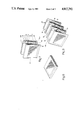
- FIG. 1 shows a top view of a closed individual container accommodating another container indicated by broken lines;
- FIG. 2 shows a side view of the individual container of FIG. 1;
- FIG. 3 shows the same individual container as FIGS. 1 and 2, but in the open position, in which the rear wall portion and the front wall portion of the individual container are held in spaced position by the parallelogram-like guide formed by the two links on both sides of the container;
- FIG. 4 shows a side view of two connected individual containers in the extended position of the filing box formed in this manner, in which both individual containers are open;
- FIG. 5 is a diagrammatic front view of two connected individual containers, the connecting means being formed by dovetail-like structures at the marginal portions of the containers;
- FIG. 6 shows an enlarged view of a locking lip at one upper bent-off side wall portion of a container which snaps behind a front wall or a rear wall of the container;
- FIG. 7 shows an open, perspective view of an individual container with a cassette arranged therein
- FIG. 8 shows a perspective view of the same container in the closed position
- FIG. 9 shows a perspective view of three individual containers assembled to each other by their respective front or rear walls, in the extended open position, whereby a multiple filing box is formed;
- FIG. 10 shows an enlarged, diagrammatic partial side view, with certain parts left away, illustrating a lower connection link with joints on both ends in the form of film hinges;
- FIG. 11 shows the same view as FIG. 10 but in the open position of the container, with retaining and guiding means provided on the links acting upon the cassette received in the container;
- FIG. 12 shows a representation similar to FIG. 10, but turned by 90°, illustrating the inner guiding and retaining tongue arranged on the respective link and projecting inwardly, i.e. toward the cassette.
- the respective individual containers intended for accommodating a plate-shaped object can be opened in such a manner that a rear wall portion is pulled away from the respective front wall portion of the individual container, but retained thereon by means of a parallelogram-like guide, and that the respective individual containers can be fitted and assembled to each other by their front and rear walls.
- This provides the multiple storage container, which may be described also as multiple filing box, and to which the properties of each individual containers are transferred insofar as the whole filing box can be opened and closed by means of the respective parallelogram guides of the individual containers.
- the individual containers form at the same time the packing for the respective plate-like goods (cassette) and may be closed all-round. They can be stacked at a minimum of space by means of the connection means provided between them and form at the same time the common multiple filing box.
- Each individual container 10 (cf. FIGS. 1, 2 and 3) consists of a rear wall portion 11 and a front wall portion 12.
- the two wall portions are interconnected by means of links 13a, 13b arranged laterally on their outsides.
- the links can be bent off in the form of joints at the points where they join the rear wall portion 11 and the front wall portion 12, which means that they are fixed to the latter in the form of hinges.
- the greatest distance by which the front wall portion of each individual container can be spaced from the rear wall portion in the open condition of the container is approximately equal to the length of the links 13a, 13b (on both sides), it being understood that both the front wall portion and the rear wall portion may comprise other parts of the individual container, in addition to the rear wall and the front wall.
- the rear wall 11 comprises, for example, in addition the lower marginal edge or the lower side wall 14 and at least certain portions of the two lateral side walls 15a, 15a', the latter being not shown in the representation of FIG. 3.
- the front wall portion 12 then comprises the upper marginal edge or upper side wall 16 and another portion of the lateral side walls, in this case the upper portion 15b, 15b'.
- the closing movement of the individual container 10 is effected until the closed position shown in FIG. 2 is reached in which the two lateral partial side walls 15a, 15b are in contact with each other along their inclined partition line 16, while the preferably thin, flat links 13a, 13b are in the retracted position in which they rest against the side wall surfaces 17 which are uncovered in the open condition of the container.
- the upper marginal edge or side wall 16 also extends over the plate-like object or the cassette 18 placed in the container 10 covering and enclosing the cassette completely, so that each individual container 10 forms at the same time the packing and/or shipping or transport envelop for the cassette 18 in which the cassette is marketed and sold.
- the individual container 10 is part of a multiple filing box--an aspect which will be described in greater detail further below.
- FIG. 7 shows very clearly that the respective parts 15a, 15a'; 15b, 15b' of the rear wall portion and/or the front wall portion have a certain thickness and serve as lateral guides for the cassette 18 which is placed in the rear wall portion 11 in the open condition of the container, the lower stop for the downwardly directed inserting movement of the cassette 18 being formed by the lower bent-off marginal edge or lower side wall 14 of the rear wall portion 11.
- the two links namely the upper link 13a and the lower link 13b may--as illustrated by the embodiment shown in the drawing--take the form of flat strips formed integrally with the lateral side wall portions 15a', 15b' and the joints between the links and the side wall portions may be constituted by integrally formed film hinges.
- the film hinges are designed in such a manner that they present a pre-determined resilient restoring force which tends to return the individual container to its closed position, so that when the individual container has been opened and/or the whole multiple filing box, which consists of a corresponding number of individual containers, has been pulled open, the individual container or the multiple filing box has the tendency to close, or to return to its original position.
- Such biasing of the links may, if used, help maintain the closed condition of each individual container. According to an advantageous further improvement of the invention, this is also ensured by the fact that--as can be seen best in FIG. 6--the bent-off upper and/or lower marginal edges are provided with a downwardly projecting locking tongue 21 at least at a pre-determined point, approximately at its center at 20 (FIG. 1). In the fully closed position of the container, this tongue engages a corresponding opening or recess in the respective other wall portion and acts to keep the container closed, at a certain pre-stress, until the container is opened manually.
- the moving mechanism including the related side wall portions for example the area encircled by the line 22 in FIG. 4, separately from a plastic material which is particularly well suited for the production of film hinges, for example by injection molding or in any other suitable manner, and to connect these parts later in a suitable manner to the remaining parts which may consist of any other plastic material, including a transparent material.
- This separate production of the parts ensuring the movement of the container is indicated by the transverse lines 23 on the lateral side walls 15a, 15b, 15a', 15b'.
- the connection to the remaining parts may be effected by conventional snap or latching mechanisms which need not be described here in greater detail, or else by gluing, welding or the like.
- a container 18 may drop through the space between the rear wall portion and the front wall portion during insertion, for example due to carelessness or a rapid movement
- the lateral side walls and/or the links 13a, 13b connected thereto or formed integrally therewith are additionally provided with inwardly projecting parts in the form of tongues or retaining means which are designated by reference numeral 24 in FIG. 12 and which will be described hereafter as retaining tongues.
- the retaining tongues 24, therefore, extend transversely to the links 13a, 13b and, in the case of the embodiment shown in FIGS. 10, 11 and 12, transversely to the lower link 13b.
- FIG. 10 shows an enlarged representation of a detail of the side wall, comprising the lower side wall portion 15a' and the lower link 13b which is fixed to the latter via a film joint 19. At its upper end, the link 13b is connected via another film joint 19 to the upper side wall portion 15b' which in this case is part of the front wall 12.
- the retaining tongues 24 are additionally provided with retaining projections or pressure parts serving to retain the cassette in its position at the rear wall. These projections will be described hereafter as retaining projections 25 and extend downwardly beyond the lower hinge or joint 19 so that during the opening movement of each individual container they will pivot inwardly, about the imaginary axis formed by the pivot point 19 and indicated by 26 in FIG.
- connection can be effected by U-shaped connection pins 27 which are inserted at different heights on both sides, bridging two cassettes. This can be seen best in the representation of FIG. 9, in the area of the inclined side wall surfaces encircled by the line 28.
- Another possibility consists in providing corresponding retaining means formed by projections extending from one of the wall surfaces, or their marginal areas, and matching corresponding recesses in the other wall surface, so that the individual containers can be clicked or snapped in place, whereby a multiple filing box structure is obtained, depending on the number of the individual containers used.
- connection between individual cassettes may consist of a dovetail-like structure as illustrated on both sides of FIG. 5, at 28.
- one surface of each individual container is provided with a dovetail-like projection, preferably in its marginal area, for engaging a dovetail-like recess in the other wall of the adjoining individual container.
- the dovetail structures may, preferably, be slightly conical, i.e. taper by only 1°, so that they provide not only a firm connection but only a safe automatic locking effect which makes the connection safe against unwanted detachment.
- a multiple filing box composed in this manner and indicated by reference numeral 100 constitutes an ideal, space-saving storing means, especially for delicate goods, the individual containers, which are initially intended as packing for the individual goods, being in a position, due to their particular structure, to impart to the multiple filing box also the advantageous properties which can be provided by the different multiple storage container specified by the before-mentioned Utility Patent No. G 86 02 838.3 and which have been described in detail with reference to the latter.
- the arrangement enables the cassettes to be stored in a space-saving manner, since the dimensions of the filing box are drastically reduced in the closed condition. Further, it is ensured that none of the individual containers is thrown around, may get lost or that the filing system may get into disorder by different stacking methods.
Landscapes
- Packages (AREA)
- Packaging For Recording Disks (AREA)
- Packaging Of Annular Or Rod-Shaped Articles, Wearing Apparel, Cassettes, Or The Like (AREA)
- Stackable Containers (AREA)
- Details Of Rigid Or Semi-Rigid Containers (AREA)
- Packging For Living Organisms, Food Or Medicinal Products That Are Sensitive To Environmental Conditiond (AREA)
Applications Claiming Priority (2)
| Application Number | Priority Date | Filing Date | Title |
|---|---|---|---|
| DE3724961A DE3724961C1 (de) | 1987-07-28 | 1987-07-28 | Mehrteiliger Aufnahmebehaelter fuer mehrere plattenfoermige Aufzeichnungsgraeger |
| DE3724961 | 1987-07-28 |
Publications (1)
| Publication Number | Publication Date |
|---|---|
| US4817792A true US4817792A (en) | 1989-04-04 |
Family
ID=6332525
Family Applications (1)
| Application Number | Title | Priority Date | Filing Date |
|---|---|---|---|
| US07/220,580 Expired - Fee Related US4817792A (en) | 1987-07-28 | 1988-07-18 | Individual container that can be assembled to a multiple storage container |
Country Status (10)
| Country | Link |
|---|---|
| US (1) | US4817792A (fr) |
| EP (1) | EP0301417B1 (fr) |
| JP (1) | JPS6484883A (fr) |
| KR (1) | KR890002875A (fr) |
| AT (1) | ATE80491T1 (fr) |
| DE (2) | DE3724961C1 (fr) |
| ES (1) | ES2035181T3 (fr) |
| GR (1) | GR3006457T3 (fr) |
| HK (1) | HK46193A (fr) |
| SG (1) | SG13593G (fr) |
Cited By (22)
| Publication number | Priority date | Publication date | Assignee | Title |
|---|---|---|---|---|
| US5161682A (en) * | 1990-04-12 | 1992-11-10 | Kurz Kunststoffe Gmbh & Co. | Multi-sectional storage receptacle |
| US5180058A (en) * | 1991-11-25 | 1993-01-19 | Pro Eton Corporation | Expandable disc holder assembly |
| USD335215S (en) | 1992-01-06 | 1993-05-04 | Atlanta Precision Molding Co. | Storage container for disk-shaped object |
| US5213229A (en) * | 1992-11-10 | 1993-05-25 | Yoshihiko Taniyama | Motion limiting mechanism for storage containers |
| US5267647A (en) * | 1992-04-16 | 1993-12-07 | Sony Corporation | Storage container for mini-disk cartridges |
| USD342379S (en) | 1992-07-08 | 1993-12-21 | Yoshihiko Taniyama | Storage container for a miniature disk cartridge |
| US5289616A (en) * | 1992-09-08 | 1994-03-01 | Yoshihiko Taniyama | Hinge with motion limiting mechanism |
| US5293992A (en) * | 1992-12-07 | 1994-03-15 | Warner Chad H | Unitary holder for two CD boxes which can be combined with one or more identical holders for storing a plurality of CD boxes |
| US5310054A (en) * | 1992-04-16 | 1994-05-10 | Sony Corporation | Storage container for disk-shaped object |
| US5334904A (en) * | 1991-01-16 | 1994-08-02 | Kramer Dale C | Compact disc case |
| WO1994018095A1 (fr) * | 1993-02-04 | 1994-08-18 | Yoshihiko Taniyama | Systeme de conteneur de stockage extensible |
| US5344039A (en) * | 1992-09-08 | 1994-09-06 | Yoshihiko Taniyama | Storage container |
| USD352199S (en) | 1992-05-26 | 1994-11-08 | Sony Corporation | Storage container for a mini-optical disc cartridge |
| US5363956A (en) * | 1993-02-22 | 1994-11-15 | Yoshihiko Taniyama | Container for plurality of stackable objects |
| US5383554A (en) * | 1991-06-11 | 1995-01-24 | Cowan; David M. | Container for storing and displaying an article |
| US5388713A (en) * | 1993-04-14 | 1995-02-14 | Taniyama; Yoshihiko | Storage container |
| US5495940A (en) * | 1992-04-16 | 1996-03-05 | Sony Corporation | Storage container for mini-disk cartridges |
| US6523700B2 (en) | 2001-03-29 | 2003-02-25 | Michel Nadeau | Display and storage receptacle for compact disc cases |
| US20030222454A1 (en) * | 2002-05-21 | 2003-12-04 | F. Baker Williams | Bias Binding |
| GB2393176A (en) * | 2002-08-23 | 2004-03-24 | Hung Kan Woo | Storage unit for flat objects such as disks |
| US10028579B2 (en) * | 2017-06-08 | 2018-07-24 | Brant Kantor | Collator |
| CN113023117A (zh) * | 2021-04-28 | 2021-06-25 | 深圳市裕同包装科技股份有限公司 | 可双向打开的多层展示盒 |
Families Citing this family (1)
| Publication number | Priority date | Publication date | Assignee | Title |
|---|---|---|---|---|
| KR100547901B1 (ko) * | 2001-05-08 | 2006-02-01 | 현대중공업 주식회사 | 컨베이어 롤러 상에서 이동하는 부재의 용접을 위한 자동접지장치 |
Citations (7)
| Publication number | Priority date | Publication date | Assignee | Title |
|---|---|---|---|---|
| US3592344A (en) * | 1968-12-26 | 1971-07-13 | Nat Blank Book Co | Collapsible sectional bookcase unit |
| US3933268A (en) * | 1973-01-13 | 1976-01-20 | Fritz Buske | Container |
| US4496050A (en) * | 1983-06-24 | 1985-01-29 | Ernst Stadelmann Gesellschaft M.B.H. | Case for holding flat articles |
| US4546898A (en) * | 1983-01-11 | 1985-10-15 | C. I. Kasei Co., Ltd. | Box |
| US4684017A (en) * | 1984-06-11 | 1987-08-04 | Kanebo Limited | Compact case |
| US4750611A (en) * | 1985-07-18 | 1988-06-14 | Morrone James V | Media storage apparatus |
| US4765469A (en) * | 1986-02-05 | 1988-08-23 | Kurz Kunststoffe Gmbh | Multisectional storage container |
Family Cites Families (5)
| Publication number | Priority date | Publication date | Assignee | Title |
|---|---|---|---|---|
| GB794216A (en) * | 1955-01-07 | 1958-04-30 | Jacques Marie Lionel Borel | Apparatus for selectively holding gramophone records or the like |
| DE2609881A1 (de) * | 1976-03-10 | 1977-09-15 | Bernhard Dietz | Behaelter fuer magnetbandkassetten |
| EP0134281A1 (fr) * | 1983-08-29 | 1985-03-20 | idn inventions and development of novelties ag | Dispositif pour le rangement de disques audio et vidéo |
| US4706396A (en) * | 1984-03-24 | 1987-11-17 | Sanki Vinyl Kabushiki Kaisha | File |
| DE8602838U1 (de) * | 1986-02-05 | 1986-05-22 | Kurz Kunststoffe GmbH, 7452 Haigerloch | Mehrteiliger Aufnahmebehälter |
-
1987
- 1987-07-28 DE DE3724961A patent/DE3724961C1/de not_active Expired
-
1988
- 1988-07-18 US US07/220,580 patent/US4817792A/en not_active Expired - Fee Related
- 1988-07-22 AT AT88111795T patent/ATE80491T1/de active
- 1988-07-22 EP EP88111795A patent/EP0301417B1/fr not_active Expired - Lifetime
- 1988-07-22 ES ES198888111795T patent/ES2035181T3/es not_active Expired - Lifetime
- 1988-07-22 DE DE8888111795T patent/DE3874451D1/de not_active Expired - Fee Related
- 1988-07-26 KR KR1019880009396A patent/KR890002875A/ko not_active Withdrawn
- 1988-07-27 JP JP63185681A patent/JPS6484883A/ja active Pending
-
1992
- 1992-12-04 GR GR920402813T patent/GR3006457T3/el unknown
-
1993
- 1993-02-09 SG SG135/93A patent/SG13593G/en unknown
- 1993-05-13 HK HK461/93A patent/HK46193A/xx unknown
Patent Citations (7)
| Publication number | Priority date | Publication date | Assignee | Title |
|---|---|---|---|---|
| US3592344A (en) * | 1968-12-26 | 1971-07-13 | Nat Blank Book Co | Collapsible sectional bookcase unit |
| US3933268A (en) * | 1973-01-13 | 1976-01-20 | Fritz Buske | Container |
| US4546898A (en) * | 1983-01-11 | 1985-10-15 | C. I. Kasei Co., Ltd. | Box |
| US4496050A (en) * | 1983-06-24 | 1985-01-29 | Ernst Stadelmann Gesellschaft M.B.H. | Case for holding flat articles |
| US4684017A (en) * | 1984-06-11 | 1987-08-04 | Kanebo Limited | Compact case |
| US4750611A (en) * | 1985-07-18 | 1988-06-14 | Morrone James V | Media storage apparatus |
| US4765469A (en) * | 1986-02-05 | 1988-08-23 | Kurz Kunststoffe Gmbh | Multisectional storage container |
Cited By (24)
| Publication number | Priority date | Publication date | Assignee | Title |
|---|---|---|---|---|
| US5161682A (en) * | 1990-04-12 | 1992-11-10 | Kurz Kunststoffe Gmbh & Co. | Multi-sectional storage receptacle |
| US5334904A (en) * | 1991-01-16 | 1994-08-02 | Kramer Dale C | Compact disc case |
| US5383554A (en) * | 1991-06-11 | 1995-01-24 | Cowan; David M. | Container for storing and displaying an article |
| US5180058A (en) * | 1991-11-25 | 1993-01-19 | Pro Eton Corporation | Expandable disc holder assembly |
| USD335215S (en) | 1992-01-06 | 1993-05-04 | Atlanta Precision Molding Co. | Storage container for disk-shaped object |
| US5495940A (en) * | 1992-04-16 | 1996-03-05 | Sony Corporation | Storage container for mini-disk cartridges |
| US5267647A (en) * | 1992-04-16 | 1993-12-07 | Sony Corporation | Storage container for mini-disk cartridges |
| US5310054A (en) * | 1992-04-16 | 1994-05-10 | Sony Corporation | Storage container for disk-shaped object |
| USD352199S (en) | 1992-05-26 | 1994-11-08 | Sony Corporation | Storage container for a mini-optical disc cartridge |
| USD342379S (en) | 1992-07-08 | 1993-12-21 | Yoshihiko Taniyama | Storage container for a miniature disk cartridge |
| US5289616A (en) * | 1992-09-08 | 1994-03-01 | Yoshihiko Taniyama | Hinge with motion limiting mechanism |
| US5344039A (en) * | 1992-09-08 | 1994-09-06 | Yoshihiko Taniyama | Storage container |
| US5213229A (en) * | 1992-11-10 | 1993-05-25 | Yoshihiko Taniyama | Motion limiting mechanism for storage containers |
| US5293992A (en) * | 1992-12-07 | 1994-03-15 | Warner Chad H | Unitary holder for two CD boxes which can be combined with one or more identical holders for storing a plurality of CD boxes |
| US5392906A (en) * | 1993-02-04 | 1995-02-28 | Taniyama; Yoshihiko | Expandable storage container system |
| WO1994018095A1 (fr) * | 1993-02-04 | 1994-08-18 | Yoshihiko Taniyama | Systeme de conteneur de stockage extensible |
| US5363956A (en) * | 1993-02-22 | 1994-11-15 | Yoshihiko Taniyama | Container for plurality of stackable objects |
| US5388713A (en) * | 1993-04-14 | 1995-02-14 | Taniyama; Yoshihiko | Storage container |
| US6523700B2 (en) | 2001-03-29 | 2003-02-25 | Michel Nadeau | Display and storage receptacle for compact disc cases |
| US20030222454A1 (en) * | 2002-05-21 | 2003-12-04 | F. Baker Williams | Bias Binding |
| GB2393176A (en) * | 2002-08-23 | 2004-03-24 | Hung Kan Woo | Storage unit for flat objects such as disks |
| GB2393176B (en) * | 2002-08-23 | 2004-08-04 | Hung Kan Woo | Storage unit for any flat objects, such as disks |
| US10028579B2 (en) * | 2017-06-08 | 2018-07-24 | Brant Kantor | Collator |
| CN113023117A (zh) * | 2021-04-28 | 2021-06-25 | 深圳市裕同包装科技股份有限公司 | 可双向打开的多层展示盒 |
Also Published As
| Publication number | Publication date |
|---|---|
| EP0301417A3 (en) | 1990-03-28 |
| SG13593G (en) | 1993-06-11 |
| DE3874451D1 (de) | 1992-10-15 |
| ATE80491T1 (de) | 1992-09-15 |
| EP0301417B1 (fr) | 1992-09-09 |
| HK46193A (en) | 1993-05-21 |
| DE3724961C1 (de) | 1988-09-22 |
| GR3006457T3 (fr) | 1993-06-21 |
| ES2035181T3 (es) | 1993-04-16 |
| KR890002875A (ko) | 1989-04-11 |
| EP0301417A2 (fr) | 1989-02-01 |
| JPS6484883A (en) | 1989-03-30 |
Similar Documents
| Publication | Publication Date | Title |
|---|---|---|
| US4817792A (en) | Individual container that can be assembled to a multiple storage container | |
| EP0535978B1 (fr) | Réceptacle pour cassette à bande magnétique | |
| US6554132B2 (en) | Disk protective enclosure | |
| US4807749A (en) | Container for flat recording media | |
| US4535888A (en) | Storage cassette for two or more disk-shaped high memory density information carriers | |
| US5931294A (en) | Storage container for information bearing disc devices | |
| HK181096A (en) | Container for at least one disc with high information density | |
| US5515979A (en) | Simplified jewel case management and opening for compact disk storage systems | |
| US5363956A (en) | Container for plurality of stackable objects | |
| US3743374A (en) | Storage housing for cases with hinged covers | |
| US5881872A (en) | Four-part package for storage media | |
| US5383553A (en) | Case for receiving at least one data storage disk | |
| US5707124A (en) | Unit for storing and dispensing disks | |
| US4647118A (en) | Storage container | |
| AU769382B2 (en) | Cover for compact discs | |
| US20040206641A1 (en) | Low-profile disk case | |
| US4440299A (en) | Container for at least one carrier member bearing a reeled tape-like recording medium, especially a magnetic tape cassette, and an assembly of two or more such containers | |
| JPH04507053A (ja) | カード等の平板状物のための容器 | |
| GB2276609A (en) | Storage container for a compact disc | |
| US6000537A (en) | Housing with readable side walls for a disc-shaped information carrier | |
| WO1988006794A1 (fr) | Agencement pour le stockage de supports d'enregistrement | |
| US20070012582A1 (en) | Disk protective enclosure | |
| US7650988B2 (en) | Disc case | |
| GB2144028A (en) | Holder for a magnetic tape cassette | |
| JPH05201482A (ja) | 少なくとも1枚の高密度デ−タ・ディスクのためのケ−ス |
Legal Events
| Date | Code | Title | Description |
|---|---|---|---|
| FEPP | Fee payment procedure |
Free format text: PAYOR NUMBER ASSIGNED (ORIGINAL EVENT CODE: ASPN); ENTITY STATUS OF PATENT OWNER: SMALL ENTITY |
|
| AS | Assignment |
Owner name: KURZ KUNSTSTOFFE GMBH, HAUPTSTRASSE 8, D-7452 HAIG Free format text: ASSIGNMENT OF ASSIGNORS INTEREST.;ASSIGNOR:SEIFERT, JOSEF;REEL/FRAME:004926/0500 Effective date: 19880623 |
|
| FEPP | Fee payment procedure |
Free format text: PAYER NUMBER DE-ASSIGNED (ORIGINAL EVENT CODE: RMPN); ENTITY STATUS OF PATENT OWNER: SMALL ENTITY Free format text: PAYOR NUMBER ASSIGNED (ORIGINAL EVENT CODE: ASPN); ENTITY STATUS OF PATENT OWNER: SMALL ENTITY |
|
| FPAY | Fee payment |
Year of fee payment: 4 |
|
| REMI | Maintenance fee reminder mailed | ||
| LAPS | Lapse for failure to pay maintenance fees | ||
| FP | Lapsed due to failure to pay maintenance fee |
Effective date: 19970409 |
|
| STCH | Information on status: patent discontinuation |
Free format text: PATENT EXPIRED DUE TO NONPAYMENT OF MAINTENANCE FEES UNDER 37 CFR 1.362 |