US4821531A - Refrigerant evaporator - Google Patents
Refrigerant evaporator Download PDFInfo
- Publication number
- US4821531A US4821531A US07/130,542 US13054287A US4821531A US 4821531 A US4821531 A US 4821531A US 13054287 A US13054287 A US 13054287A US 4821531 A US4821531 A US 4821531A
- Authority
- US
- United States
- Prior art keywords
- tank portion
- refrigerant
- tubes
- evaporator
- inlet
- Prior art date
- Legal status (The legal status is an assumption and is not a legal conclusion. Google has not performed a legal analysis and makes no representation as to the accuracy of the status listed.)
- Expired - Lifetime
Links
Images




Classifications
-
- F—MECHANICAL ENGINEERING; LIGHTING; HEATING; WEAPONS; BLASTING
- F28—HEAT EXCHANGE IN GENERAL
- F28F—DETAILS OF HEAT-EXCHANGE AND HEAT-TRANSFER APPARATUS, OF GENERAL APPLICATION
- F28F9/00—Casings; Header boxes; Auxiliary supports for elements; Auxiliary members within casings
- F28F9/02—Header boxes; End plates
- F28F9/0246—Arrangements for connecting header boxes with flow lines
- F28F9/0251—Massive connectors, e.g. blocks; Plate-like connectors
-
- F—MECHANICAL ENGINEERING; LIGHTING; HEATING; WEAPONS; BLASTING
- F25—REFRIGERATION OR COOLING; COMBINED HEATING AND REFRIGERATION SYSTEMS; HEAT PUMP SYSTEMS; MANUFACTURE OR STORAGE OF ICE; LIQUEFACTION SOLIDIFICATION OF GASES
- F25B—REFRIGERATION MACHINES, PLANTS OR SYSTEMS; COMBINED HEATING AND REFRIGERATION SYSTEMS; HEAT PUMP SYSTEMS
- F25B39/00—Evaporators; Condensers
- F25B39/02—Evaporators
- F25B39/022—Evaporators with plate-like or laminated elements
-
- F—MECHANICAL ENGINEERING; LIGHTING; HEATING; WEAPONS; BLASTING
- F28—HEAT EXCHANGE IN GENERAL
- F28D—HEAT-EXCHANGE APPARATUS, NOT PROVIDED FOR IN ANOTHER SUBCLASS, IN WHICH THE HEAT-EXCHANGE MEDIA DO NOT COME INTO DIRECT CONTACT
- F28D1/00—Heat-exchange apparatus having stationary conduit assemblies for one heat-exchange medium only, the media being in contact with different sides of the conduit wall, in which the other heat-exchange medium is a large body of fluid, e.g. domestic or motor car radiators
- F28D1/02—Heat-exchange apparatus having stationary conduit assemblies for one heat-exchange medium only, the media being in contact with different sides of the conduit wall, in which the other heat-exchange medium is a large body of fluid, e.g. domestic or motor car radiators with heat-exchange conduits immersed in the body of fluid
- F28D1/03—Heat-exchange apparatus having stationary conduit assemblies for one heat-exchange medium only, the media being in contact with different sides of the conduit wall, in which the other heat-exchange medium is a large body of fluid, e.g. domestic or motor car radiators with heat-exchange conduits immersed in the body of fluid with plate-like or laminated conduits
- F28D1/0308—Heat-exchange apparatus having stationary conduit assemblies for one heat-exchange medium only, the media being in contact with different sides of the conduit wall, in which the other heat-exchange medium is a large body of fluid, e.g. domestic or motor car radiators with heat-exchange conduits immersed in the body of fluid with plate-like or laminated conduits the conduits being formed by paired plates touching each other
- F28D1/0325—Heat-exchange apparatus having stationary conduit assemblies for one heat-exchange medium only, the media being in contact with different sides of the conduit wall, in which the other heat-exchange medium is a large body of fluid, e.g. domestic or motor car radiators with heat-exchange conduits immersed in the body of fluid with plate-like or laminated conduits the conduits being formed by paired plates touching each other the plates having lateral openings therein for circulation of the heat-exchange medium from one conduit to another
- F28D1/0333—Heat-exchange apparatus having stationary conduit assemblies for one heat-exchange medium only, the media being in contact with different sides of the conduit wall, in which the other heat-exchange medium is a large body of fluid, e.g. domestic or motor car radiators with heat-exchange conduits immersed in the body of fluid with plate-like or laminated conduits the conduits being formed by paired plates touching each other the plates having lateral openings therein for circulation of the heat-exchange medium from one conduit to another the plates having integrated connecting members
- F28D1/0341—Heat-exchange apparatus having stationary conduit assemblies for one heat-exchange medium only, the media being in contact with different sides of the conduit wall, in which the other heat-exchange medium is a large body of fluid, e.g. domestic or motor car radiators with heat-exchange conduits immersed in the body of fluid with plate-like or laminated conduits the conduits being formed by paired plates touching each other the plates having lateral openings therein for circulation of the heat-exchange medium from one conduit to another the plates having integrated connecting members with U-flow or serpentine-flow inside the conduits
-
- F—MECHANICAL ENGINEERING; LIGHTING; HEATING; WEAPONS; BLASTING
- F28—HEAT EXCHANGE IN GENERAL
- F28F—DETAILS OF HEAT-EXCHANGE AND HEAT-TRANSFER APPARATUS, OF GENERAL APPLICATION
- F28F9/00—Casings; Header boxes; Auxiliary supports for elements; Auxiliary members within casings
- F28F9/02—Header boxes; End plates
- F28F9/026—Header boxes; End plates with static flow control means, e.g. with means for uniformly distributing heat exchange media into conduits
- F28F9/027—Header boxes; End plates with static flow control means, e.g. with means for uniformly distributing heat exchange media into conduits in the form of distribution pipes
Definitions
- the present invention relates to heat exchangers that may be used as evaporators in a refrigeration/air conditioning system. It is particularly well suited for use in an automotive vehicle air conditioning system.
- Japanese examined utility model (Koukoku) No. 53-32378 discloses a heat exchanger used as an evaporator of the type shown in FIG. 19. It has a plurality of tube-units 510 each formed by a pair of plates 511 and 512 joined to each other. Each tube-unit 510 has a U-shaped tube portion 516 and a first tank portion 515 and a second tank portion 518 disposed at opposite ends of the tube portion. Tube-units 510 are connected to each other with corrugated fins 517 disposed between them.
- An inlet pipe 501 is joined to the first tank portion 515 disposed at one end of the U-shaped tube for introducing refrigerant therethrough.
- An outlet pipe 502 is joined to the second tank portion 518 disposed at the other end of the U-shaped tube 516 for allowing refrigerant to flow out from the second tank portion.
- FIG. 20 graphically illustrates the relationship between a flow pattern of refrigerant in various evaporator configurations and a temperature gradient (as a function of position along the heat exchanger) of air passed through the heat exchanger when it is used as an evaporator of refrigerant.
- the refrigerant flow pattern for various structural arrangements of heat exchangers is shown schematically in the upper portions of FIG. 20 and the air temperature just downstream of the heat exchanger is indicated at a lower portion of FIG. 20.
- refrigerant introduced into the first tank portion 515 through the inlet pipe 501 flows to the second tank portion 518 through the U-shaped tube portions 516.
- the temperature of the air gradually decreases from the position close to the inlet pipe to the position close to the outlet pipe.
- the evaporator which is indicated in the "B" portion of FIG. 20 has a separate plate 520 in the first tank portion 515.
- the refrigerant flow into the front portion 515a of the first tank portion 515 through the inlet pipe 501 is interrupted so that the refrigerant flows into the second tank portion 518 through the U-shaped tube 516 which opens to the front portion 515a of the first tank portion 515.
- the refrigerant introduced into the second tank portion 518 then flows toward the rear portion 515b of the first tank portion 515 through the U-shaped tube 516 which opens to the rear portion.
- Refrigerant which has flowed into the first tank portion 515 flows out through the outlet pipe 502.
- the temperature of air gradually decreases from the position close to the inlet pipe 501 to the position close to the separate plate 520.
- the temperature of air is high at a portion of the evaporator that corresponds to a flow of refrigerant downstream of the separate plate 520 and gradually decreases from the position close to the inlet pipe 501 to the position close to the separate plate 520.
- the temperature of air is high at the downstream of the separate plate 520 and gradually decreases from the position close to the separate plate 520 to the position close to the outlet pipe 502.
- a separate plate 520a is disposed in the first tank portion 515 in order to divide the first tank portion 515 into a front portion 515a and a rear portion 515b and a separate plate 520b is disposed in the second tank portion 518 in order to divide the second tank portion 518 into a front portion 518a and a rear portion 518b.
- the refrigerant flowed into the tank portion 515 through the inlet pipe 501 is interrupted by the separate plate 520a, so that the refrigerant flows into the front portion 518a of the second tank portion 518 through the U-shaped tube 516.
- the refrigerant flows into the rear portion 515b of the first tank portion 515 through the U-shaped tube 516 which connects the front portion 518a of the second tank portion 518 and the rear portion 515b to the first tank portion 515.
- the refrigerant flows from the rear portion 515b of the first tank portion 515 to the rear portion 518b of the second tank portion 518 through the U-shaped tube 516 which connects the rear portion 515b of the first tank portion 515 and the rear portion 518b of the second tank portion 518.
- the temperature of air becomes low at the upstream of the separate plate 520a or the separate plate 520b and becomes high downstream of them.
- FIG. 21 is a schematic diagram of the flow pattern of the refrigerant in a conventional evaporator.
- Refrigerant flows into the tank portion 515 through the inlet pipe 501 in a gas-liquid phase. Mist of the liquid refrigerant is mixed with gas refrigerant.
- the quantity and velocity of refrigerant flowing in the tank portion and the tube portion increases, especially when the heat exchanging capacity required for the evaporator becomes high.
- the force of inertia of the liquid refrigerant in tank portion 518 flowing toward the wall shown in the right side of FIG. 21 increases with high velocity flow of refrigerant.
- the quantity of liquid refrigerant around the inlet port is, therefore, much smaller than that of the liquid refrigerant in front of the wall, namely downstream.
- a large amount of the liquid refrigerant mixed in the gas refrigerant as a mist flows toward the wall 521 in the tank portion 518 by the force of inertia.
- the liquid refrigerant mainly flows into the U-shaped tube portion opening ahead of an end wall of the tank portion and the gas refrigerant mainly flows into the U-shaped tube portion opening around the inlet pipe. Therefore there is an imbalance of distribution of refrigerant flowing into the tube portion. Such imbalance causes the temperature gradient of air output across the width of the evaporator to be uneven.
- FIG. 34 is a schematic view of a conventional evaporator.
- a first tank portion 311 has an inlet port 314 at the left side thereof.
- One end of each a plurality of tubes 313 is connected to the first tank portion 311 and the other end of each of tubes 313 is connected to a second tank portion 312.
- the second tank portion 312 has an outlet port 315 at the right side thereof from which refrigerant flows.
- FIG. 31 is a schematic view of the present invention.
- the central concept of the invention is to provide a plurality of substantially equal flow paths for refrigerant along the entire width of the evaporator.
- a first tank portion 311 has an inlet port 314 for introducing the refrigerant thereinto and each one end of a plurality of tubes 313 are connected thereto.
- tubes 313 are connected to a second tank portion 312, and the refrigerant introduced into the first tank portion 311 flows into the second tank portion 312 through each of tubes 313.
- the second tank portion 312 has a outlet port 315 for deriving the refrigerant therefrom.
- the structure of the evaporator is designed so that the length of the refrigerant flow for each point along the width of the evaporator is substantially the same.
- a plurality of tubes 313 connect a first tank portion 311 with a second tank portion 312.
- the first tank portion has an inlet port 314 and the second tank portion has an outlet port 315.
- the tubes and inlet and outlet ports are arranged so as to even the flow of refrigerant along the evaporator.
- the length of the refrigerant flow passage via one of a pair of tubes 313 one end of which is connected at a position closer to the inlet port 314 along with the direction of the refrigerant flow within the first tank portion 3-1 than a position at which one end of another one of the pair of the tubes 313 is connected is longer than the length of the refrigerant flow passage via another pair of tubes 313.
- the inlet port 314 and the outlet port 315 are disposed at the first tank portion 311 and the second tank portion 312 respectively in such a manner that directions of the refrigerant flow within the first tank portion 311 and the second tank portion 312 are opposite to each other.
- one end of a first tube 313a among the plurality of tubes 313 is connected to the first tank portion 311 closer to one end of the first tank portion 311 than a portion at which one end of a second tube 313b among the plurality of tubes 313 is connected.
- the other end of the first tube 313a is connected to the second tank portion 313 closer to the other end of the second tank portion 313 than the other end of the second tube 313b.
- the inlet port 314 is disposed at a position close to one end of the first tank portion 311 and the outlet port 315 is disposed at the position close to one end of the second tank portion 312.
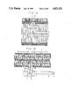
- FIG. 1 is a top view of an evaporator representative of a first embodiment of the present invention.
- FIG. 2 is a perspective view of the first embodiment of the invention.
- FIG. 3 is a front view of a main plate.
- FIG. 4 is a sectional view taken along line IV--IV in FIG. 3.
- FIG. 5 is a sectional view taken along line V--V in FIG. 3.
- FIG. 6 is a front view of a central plate.
- FIG. 7 is a sectional view taken along line VII--VII in FIG. 6.
- FIG. 8 is a sectional view taken along line VIII--VIII in FIG. 6.
- FIG. 9 is a front view of an inlet piping unit.
- FIG. 10 is a sectional view taken along line X--X in FIG. 9.
- FIG. 11 is sectional view taken along line XI--XI in FIG. 9.
- FIG. 12 is a sectional view taken along line XII--XII in FIG. 10.
- FIG. 13 is a top view of an evaporator according to a second embodiment of the invention.
- FIG. 14 is a front view of the second embodiment of the invention.
- FIG. 15 is a top view of an evaporator representative of a third embodiment of the invention.
- FIG. 16 is an enlarged view of an important portion of FIG. 15.
- FIG. 17 is a top view of an evaporator representative of a fourth embodiment of the invention.
- FIG. 18 is an enlarged view of an important portion of FIG. 17.
- FIG. 19 is a front view showing a conventional evaporator.
- FIGS. 20a-c are diagrams showing the manner of flowing in the conventional evaporator.
- FIG. 21 is a diagram showing in greater detail the stream of a refrigerant in the conventional evaporator.
- FIG. 22 is a perspective view showing the conventional evaporator.
- FIG. 23 is a top view of an evaporator representative of a fifth embodiment of the invention.
- FIG. 24 is a front view of a main plate.
- FIG. 25 is a sectional view taken along line XXV in FIG. 24.
- FIG. 26 is a front view of a inlet piping unit.
- FIG. 27 is a sectional view taken along XXVII--XXVII in FIG. 26.
- FIG. 28 is a sectional view of a nozzle.
- FIG. 29 is diagram showing a relation of a length of nozzle and a temperature deviation of air.
- FIG. 30 is a diagram showing a relation between a shape of nozzle and flowing loss.
- FIG. 31 and FIG. 32 are schematic views showing of the present invention.
- FIG. 33 is a schematic diagram of various embodiments of the invention.
- FIG. 34 is a schematic diagram of a conventional evaporator.
- FIG. 2 is a perspective view of the refrigerant evaporator
- FIG. 1 is a top view of the evaporator shown in FIG. 2 wherein a central portion and right-hand side portion are illustrated in cross section.
- This evaporator 1 is formed by laminating a plurality of tube units 7 in the same direction.
- a tube unit 7 is formed by joining a pair of plates shown in FIGS. 3 through 5 together in confronting relation.
- FIG. 3 is a plan view of one main plate 7a to form the tube unit 7.
- FIG. 4 is a sectional view taken along line IV--IV in FIG. 3
- FIG. 5 is a sectional view taken along the line V--V in FIG. 3.
- Main plate 7a is made of an aluminum material having a thickness of about 0.5-0.6 mm with both sides clad with brazing material, which is shaped by press-working.
- the main plate 7a has at its one end a tank recess portion 702 and another tank recess portion 703 which are each press-formed into an elliptical shape.
- the main plate 7a is formed with a substantially U-shaped passage recess portion 701 connecting the tank recess portion 702 and the tank recess portion 703.
- this passage recess portion 701 are formed a plurality of embossed ribs 707 by embossing-forming, and a center rib 708 is also provided by embossing-forming in the central portion of the main plate 7a to make a U shape.
- the bottoms of the tank recess portion 702 and the tank recess portion 703 are formed respectively with holes 704 and 705 for refrigerant to flow through. Further, around the hole 705 is formed a burring portion 706 serving as positioning means at the time of assembly of the evaporator.
- the tube unit 7 By joining a pair of main plates 7a shown in FIGS. 3 through 5 together in confronting relation, there is formed the tube unit 7 having the U-shaped tube portion and the tank portions at either end thereof.
- the refrigerant evaporator 1 By laminating a plurality of such tube units 7 in the same direction, there is formed the refrigerant evaporator 1, to which an inlet piping unit 2A and an outlet piping unit 2B are attached in a substantially central portion of the evaporator 1.
- the inlet piping unit 2A and the outlet piping unit 2B are substantially identical in configuration, this being illustrated in FIGS. 9 through 12.
- Each of the inlet piping unit 2 and the outlet piping unit 2B is formed by a pair of piping unit forming plates 2a and 2b arranged in confronting relation.
- a first space 40 and a second space 50 in the inside.
- the piping unit forming plate 2a is bored with a communicating hole 100 opposite to first space 40.
- the inlet piping unit forming plate 2b is bored with a communicating hole 101 opposite to first space 40.
- the communicating hole 100 is made larger in the area of opening than the communicating hole 101.
- the inlet piping unit forming plates 2a and 2b are bored also with respective holes 102 and 103 opposite to second space 50 for passage of the refrigerant.
- the outlet piping unit 2B is formed by joining two forming plates together in confronting relation, leaving a first space 61 and a second space 71 inside.
- the second space 71 has on its either side communicating holes 104, and on the right-hand side in FIG. 1 of the first space 61 is formed an opening 103.
- This first space 61 has this opening 103 only.
- a central tube unit 9 formed by central plates 9a is disposed and held at the position between the inlet piping unit 2A and the outlet piping unit 2B.
- This central tube unit 9 is formed by joining a pair of central plates 9a shown in FIGS. 6 through 8 together in confronting relation.
- the central plate 9a is substantially identical in configuration with the aforementioned tube plate 7a and has a U-shaped passage-forming recess 901 and tank-forming recess portions 902 and 903 at either end thereof.
- the bottoms of the tank-forming recess portions 902 and 903 ar bored with respective holes 904 and 905 for passage of the refrigerant.
- the difference between the central plate 9a and the tube plate 7a resides in the recession depth H of the tank recess portions 902 and 903. That is, the recession depth H of the tank recesses 902 and 903 of the central plate 9a is made smaller than the recession depth of the tube plate.
- a burring 906 is formed around the hole 904.
- a plurality of ribs 907 are formed in the passage-forming recess portion 901 by embossing, and in the central portion is formed a center rib 908 by embossing.
- the communicating hole 905 is made smaller in the area of opening than the communicating hole 904.
- the central tube unit 9 has a first space 48 and a second space 58 therein.
- the first space 48 is communicated with the first space 40 of the inlet piping unit 2A through the communicating hole 904 bored in the central plate 9a.
- the second space 58 of the central tube unit 9 is communicated via the communicating hole 904 with the second space 50 of the inlet piping unit 2A and the second space 71 of the outlet piping unit 2B.
- the first space 48 of the central tube unit 9 is isolated from the first space 61 of the outlet piping unit 2B. Accordingly, the first space 40 of the inlet piping unit 2A and the first space 61 of the outlet piping unit 2B are in a non-communicating state.
- the central plates 9a are disposed individually on the left-hand side in FIG. 1 of the inlet piping unit 2A and on the right-hand side in FIG. 1 of the outlet piping unit 2B.
- the communicating holes 905 of the central plates 9a disposed on the respective sides of the inlet and outlet piping units 2A and 2B are made larger than that of the central plate 9a shown in FIG. 7.
- the first space 40 of the inlet piping unit 2A is communicated via the communicating hole 100 and the communicating hole 905 of the central plate 9a with the tank portions of the tube units 7 positioned on the left-hand side of FIG. 1. Accordingly, the refrigerant invited through the inlet piping unit 2A forming an inlet port flows through the first space into the tank portions of the tube units 7.
- the tank portions of the tube units 7 permitting air inflow through the first space 40 of the inlet piping unit 2A form an inlet tank portion 200 as a first tank portion of the present invention.
- a plurality of tubes 41 through 47 communicating with the inlet tank portion 200 constitute a first tube group 401.
- This first tube group 401 has other tank portions provided at the other end which constitute an intermediate tank portion 201.
- the intermediate tank portion 201 is formed over the whole width of the refrigerant evaporator 1, this intermediate tank portion 201 being communicated with a second tube group 402 similarly U-shaped.
- the intermediate tank portion 201 forms a second tank portion 201a of one refrigerant evaporator which is connected with the other refrigerant evaporator in series and a first tank portion 201b of the other refrigerant evaporator.
- a portion of the intermediate tank portion 201 to which the first tube group 401 is connected forms the second tank portion 201a, and a portion of the intermediate tank portion 201 to which the second tube group 402 is connected forms the first tank portion 201b.
- the communicating hole 904 of the central tube unit 9 confronting the second tank portion 201a forms an outlet port of one refrigerant evaporator and another communicating hole 904 of the central tube unit 9 confronting the first tank portion 201b forms an inlet port of another refrigerant evaporator.
- This second tube group 402 has an outlet tank portion 202 as a second tank portion of another refrigerant evaporator provided at the other end.
- the inlet piping unit 2A forming the inlet port is connected with a clad pipe 12, while the outlet piping unit 2B forming an outlet port is similarly connected with another clad pipe 12.
- the other ends of these clad pipes 12 are connected with an expansion valve housing 4.
- This expansion valve housing 4 is connected with an outlet piping unit 2B and inlet piping unit 2A.
- the outlet piping is connected with the outlet piping unit 2B, while the inlet piping unit 2A is connected via a publicly-known expansion valve with the inlet piping unit 2A.
- Evaporator 1 has side plates 11 disposed on either side thereof for the purpose of its reinforcement.
- inlet piping unit 2A and the outlet piping unit 2B are connected via the clad pipes 12 with the expansion valve housing 4
- inlet piping unit 2A and outlet piping unit 2B may be directly connected with the expansion valve housing 4 without using the clad pipes 12.
- Refrigerant from a condenser of an automotive air conditioner flows through the expansion valve disposed inside the expansion valve housing 4 and the inlet piping unit 2A into the first space 40. Then, the refrigerant flows from space 40 into the inlet tank portion 200. The refrigerant flows from inlet tank portion 200 through the U-shaped flow paths of the first tube group 401 and into the intermediate tank portion 201.
- the refrigerant flows from intermediate tank portion 201a positioned in the left-hand half of FIG. 1 through the second spaces 50 and 71 of the inlet piping unit 2A and the outlet piping unit 2B and into the intermediate tank portion 201b positioned on the right-hand side in FIG. 1.
- the refrigerant flowing into the right hand intermediate tank portion 201b flows through the U-shaped paths of the second tube group 402 and into the outlet tank portion 202.
- the refrigerant flowing into the outlet tank portion 202 flows in the leftward direction in FIG. 1 and through the outlet piping unit 2B and the outlet piping connected in the vicinity of the center of the evaporator 1, and flows out toward the side of a compressor of the air conditioner.
- the foregoing flow of the refrigerant is indicated by the arrows F in FIG. 1.
- the sum of the length of the flow path of a stream along the end wall 16 of the inlet tank portion 200 and the length of the flow path of a stream along an end wall 15 of the intermediate tank portion 201 and reaching the outlet piping unit 2B is the longest among the lengths of the flow paths of other streams passing the respective tubes and reaching the outlet piping unit 2B.
- the flow resistance increases by a difference between them.
- the liquid phase refrigerant introduced into the inlet tank portion 200 and the intermediate tank portion 201 has a tendency to flow in a large amount toward an end wall 16 and an end wall 15 respectively
- the gas phase refrigerant introduced into the inlet tank portion 200 and the intermediate tank portion 201 has a tendency to remain at points which are close to the communicating hole 905 and the other end wall 151 of the intermediate tank portion respectively.
- the actual amount of the liquid phase refrigerant flowing into each tube is the same. Since the flow resistance of the flowing path from the inlet port to the outlet port of each tank via each tube increases in accordance with the distance between the tube and end wall 15 or the end wall 16; such flow resistance cancel the tendency described above. Therefore the variation in the temperature distribution of the air passing through the evaporator is made uniform.
- FIG. 13 shows another embodiment of the present invention, which corresponds to FIG. 1 described above.
- the central plates 9a are disposed on the respective sides of the inlet piping unit 2A and the outlet piping unit 2B, and the spacing between the inlet piping unit 2A and the outlet piping unit 2B is set narrower than the width of the tube unit 7.
- the central plate 9a is disposed on the right-hand side 7a the drawing of the piping unit 2A, and the tube main plate 7a is disposed on the left side.
- the main plate 7a is disposed on the left-hand side in the drawing of the outlet piping unit 2B, and the central plate 9 a is disposed on the right side.
- the spacing between the inlet piping unit 2A and the outlet piping unit 2B of the embodiment shown in FIG. 13 is wider than that of the embodiment shown in FIG. 1 by the difference in thickness between the main plate 7a and the central plate 9a.
- the other structures and the operation are identical with those of the first embodiment described above, hence, no description is given.
- FIG. 14 is a front view of an evaporator representative of a third embodiment of the present invention, wherein portions of the pipes are illustrated in cross section.
- FIG. 15 is a top view of the evaporator shown in FIG. 14, and
- FIG. 16 is an enlarged fragmentary sectional view of connection portions of the inlet piping 2A and the outlet piping 2B shown in FIG. 15.
- the inlet piping unit 2A and the outlet piping unit 2B constitute a part of the intermediate tank 201 also.
- the inlet piping unit 2A is joined with the inlet tank section 200 only, and the outlet piping unit 2B with the outlet tank 202 only. Accordingly, the intermediate tank section 201 is formed by successively laminating the tube units 7.
- FIG. 17 is a top view of an evaporator representative of a fourth embodiment of the present invention
- FIG. 18 is an enlarged fragmentary sectional view showing in detail connection portions of an inlet piping unit 2A and an outlet piping unit 2B shown in FIG. 17.
- the inlet piping and outlet piping are inserted in the tube units 7 formed by joining the ordinary main plates 7a together.
- This embodiment also has the structure wherein the inlet piping unit and the outlet piping are connected independently with the inlet tank section 200 and the outlet tank 202, respectively.
- the tube units of this embodiment should be formed with insertion holes to insert and connect the inlet piping unit 2A and the outlet piping unit 2B.
- the inlet piping unit 2A and the outlet piping unit 2B are provided in adjacent positional relation, hence, the efficiency of working in connecting the expansion valve housing 4 is better.
- FIG. 23 is a top view of a fifth embodiment of the invention wherein a central portion is illustrated in cross section.
- the inlet piping unit 2A and the outlet piping unit 2B are connected with the expansion valve housing 4 at the right-hand position and the left-hand position in FIG. 23 respectively.
- the inlet piping unit 2A is formed by pair of piping unit forming plates 2a and 2b in confronting relation. By joining two inlet piping unit forming plates 2a and 2b together in confronting relation. There are formed the first space 40 and the second space 50 in the inside.
- the piping unit forming plate 2a has a communicating hole 100 being opposed to the first space 40
- the piping unit forming plate 2b has a communicating hole 101 confronting the communicating hole 100.
- the communicating hole 101 has a cylindrical nozzle 300 in its periphery. An opening area of the communicating hole 101 is larger than that of the communicating hole 100, and almost all of the refrigerant entering first space 40 flows into the inlet tank portion 200 through the communicating hole 101.
- the outlet piping unit 2B is formed by a pair of piping unit forming plates in confronting relation and has a substantially identical configuration. Though, the outlet piping unit 2B has no nozzle in the periphery of the communicating hole 101.
- the central tube unit 9 is formed by the central tube forming plate shown in FIGS. 24 and 25 and the central tube forming plate 9C having a same recession depth as the main plate shown in FIGS. 3 through 5 in confronting relation.
- the central tube forming plate 9b has refrigerant passing holes 904b and 905b which have same area.
- the other central tube forming plate 9C has two tank recesses. One of the two tank recesses has a hole and the other has no hole.
- the inlet piping unit 2A and the outlet piping unit 2B are formed by joining the central tube forming plate 9b to a central tube forming plate 9C in such a manner that the tank recesses do not communicate and the tank recesses having holes form a part of the intermediate tank portion 201.
- the central tube forming plate 9C of the central tube unit 9 joined to the inlet piping unit 2A has a cylindrical nozzle 310 in a periphery of a hole formed in its tank recess.
- the nozzle 310 is opened in the direction of the refrigerant flowing in the intermediate tank portion 201.
- the tube units formed by the central tube forming plates 9b and the main plate 7 are joined to the inlet piping unit 2A and the outlet piping unit 2B at the opposite side of the central tube unit 9.
- the amount of the liquid phase refrigerant is made sufficient by modulating the diameter and the length of the nozzle 300, 310.
- FIG. 29 shows the relation between the temperature deviation of air passed through the evaporator and the length h and the diameter d of nozzle 300 which is formed in only the inlet piping unit 2A.
- the temperature deviation ⁇ is defined by the following formula. ##EQU1##
- Tan represents a temperature of air passed through the evaporator at n different points along the width of the evaporator.
- Ta represents an average of the temperatures of Tan.
- FIG. 30 shows the relation between the length h and the diameter d of nozzle 300 and the flowing loss of the refrigerant.
- the length h of the nozzle is 10 mm and the diameter d of the nozzle is 7 mm, the temperature deviation of air and the flowing loss of the refrigerant is smallest.
- the length h is 10 mm and the diameter d is 7 mm.
- the nozzle 310 formed in the central tube unit 9 is not absolutely necessary and the position of the nozzle 310 can be changed from that shown in the drawings.
- the shape of nozzles 300 and 310 may be tapered.
- FIG. 35 plots the temperature of air passed through the evaporator shown in FIG. 23. As shown in FIG. 35, the temperature is almost uniform across the entire width of the evaporator.
- FIG. 35 is derived from a test wherein the temperature of air coming through the evaporator was about 30° C., the humidity was about 60% and air flowed at a rate of 300 m 3 /hour. Evaporation pressure of the refrigerant was 2.5 kg/cm 2 , the degree of super heat of the refrigerant was 10° C. and amount of refrigerant flow was 100 l/hour.
- FIG. 33 is a schematic view of all of the embodiments described above. Two of the evaporators shown in FIG. 31 are connected to each other in series. The outlet port 315a of one of the evaporators is connected to the inlet port 314b of the other evaporator. The inlet port 314a of one of the evaporators and the outlet port 315b of the other evaporator abut each other.
- two of the evaporators shown schematically in FIG. 31 are connected to each other in series but two of them can be connected in parallel as shown schematically in FIG. 32 and only one evaporator as shown in FIG. 31 can be used.
Landscapes
- Engineering & Computer Science (AREA)
- Physics & Mathematics (AREA)
- Thermal Sciences (AREA)
- Mechanical Engineering (AREA)
- General Engineering & Computer Science (AREA)
- Heat-Exchange Devices With Radiators And Conduit Assemblies (AREA)
- Transition And Organic Metals Composition Catalysts For Addition Polymerization (AREA)
- Compression-Type Refrigeration Machines With Reversible Cycles (AREA)
- Air-Conditioning For Vehicles (AREA)
Applications Claiming Priority (4)
| Application Number | Priority Date | Filing Date | Title |
|---|---|---|---|
| JP61-295398 | 1986-12-11 | ||
| JP29539886 | 1986-12-11 | ||
| JP62255250A JP2646580B2 (ja) | 1986-12-11 | 1987-10-09 | 冷媒蒸発器 |
| JP62-255250 | 1987-10-09 |
Publications (1)
| Publication Number | Publication Date |
|---|---|
| US4821531A true US4821531A (en) | 1989-04-18 |
Family
ID=26542100
Family Applications (1)
| Application Number | Title | Priority Date | Filing Date |
|---|---|---|---|
| US07/130,542 Expired - Lifetime US4821531A (en) | 1986-12-11 | 1987-12-09 | Refrigerant evaporator |
Country Status (4)
| Country | Link |
|---|---|
| US (1) | US4821531A (fr) |
| EP (1) | EP0271084B1 (fr) |
| JP (1) | JP2646580B2 (fr) |
| DE (1) | DE3777972D1 (fr) |
Cited By (29)
| Publication number | Priority date | Publication date | Assignee | Title |
|---|---|---|---|---|
| US5137082A (en) * | 1989-10-31 | 1992-08-11 | Nippondenso Co., Ltd. | Plate-type refrigerant evaporator |
| US5172759A (en) * | 1989-10-31 | 1992-12-22 | Nippondenso Co., Ltd. | Plate-type refrigerant evaporator |
| US5355947A (en) * | 1993-10-25 | 1994-10-18 | Chrysler Corporation | Heat exchanger having flow control insert |
| US5370176A (en) * | 1993-02-10 | 1994-12-06 | Zexel Corporation | Heat exchanger apparatus |
| US5448899A (en) * | 1992-10-21 | 1995-09-12 | Nippondenso Co., Ltd. | Refrigerant evaporator |
| US5503223A (en) * | 1995-04-10 | 1996-04-02 | Ford Motor Company | Single tank evaporator core heat exchanger |
| GB2298038A (en) * | 1995-02-17 | 1996-08-21 | Gen Motors Corp | Heat exchanger and coupling member |
| US5553664A (en) * | 1993-05-20 | 1996-09-10 | Zexel Corporation | Laminated heat exchanger |
| US5632161A (en) * | 1994-06-27 | 1997-05-27 | Nippondenso Co., Ltd. | Laminated-type evaporator |
| US5680897A (en) * | 1996-09-12 | 1997-10-28 | General Motors Corporation | Plate type heat exchanger with integral feed pipe fixturing |
| EP0727625A3 (fr) * | 1995-02-16 | 1998-01-21 | Zexel Corporation | Echangeur de chaleur laminé |
| US5832989A (en) * | 1996-03-14 | 1998-11-10 | Denso Corporation | Cooling apparatus using boiling and condensing refrigerant |
| US5931020A (en) * | 1997-02-28 | 1999-08-03 | Denso Corporation | Refrigerant evaporator having a plurality of tubes |
| US6003593A (en) * | 1995-10-31 | 1999-12-21 | Denso International America, Inc. | Automotive vehicle climate control system |
| US6119767A (en) * | 1996-01-29 | 2000-09-19 | Denso Corporation | Cooling apparatus using boiling and condensing refrigerant |
| GB2366359A (en) * | 2000-05-15 | 2002-03-06 | Denso Corp | Evaporators |
| US6357517B1 (en) | 1994-07-04 | 2002-03-19 | Denso Corporation | Cooling apparatus boiling and condensing refrigerant |
| US20030019612A1 (en) * | 1996-03-14 | 2003-01-30 | Hiroyuki Osakabe | Cooling apparatus boiling and condensing refrigerant |
| US6516486B1 (en) | 2002-01-25 | 2003-02-11 | Delphi Technologies, Inc. | Multi-tank evaporator for improved performance and reduced airside temperature spreads |
| US6520251B2 (en) * | 2000-01-08 | 2003-02-18 | Halla Climate Control Corp. | Plate for stack type heat exchangers and heat exchanger using such plates |
| US20030106679A1 (en) * | 2001-10-24 | 2003-06-12 | Viktor Brost | Housing-less plate heat exchanger |
| RU2230264C2 (ru) * | 2002-07-01 | 2004-06-10 | Общество с ограниченной ответственностью "Газхолодтехника" | Испаритель |
| US20040154331A1 (en) * | 2001-02-05 | 2004-08-12 | Hirofumi Horiuchi | Duplex-type heat exchanger and refrigeration system equipped with said heat exchanger |
| US20050144978A1 (en) * | 2004-01-07 | 2005-07-07 | Papapanu Steven J. | Full plate, alternating layered refrigerant flow evaporator |
| US20050172664A1 (en) * | 2002-12-21 | 2005-08-11 | Jae-Heon Cho | Evaporator |
| US20060243422A1 (en) * | 2005-04-28 | 2006-11-02 | Denso Corporation | Liquid-cooled semiconductor unit for cooling high-power semiconductor elements that are enclosed in modules |
| US20070114012A1 (en) * | 2003-11-28 | 2007-05-24 | Akio Iwasa | Heat exchanger |
| US20100243200A1 (en) * | 2009-03-26 | 2010-09-30 | Modine Manufacturing Company | Suction line heat exchanger module and method of operating the same |
| US11014425B2 (en) * | 2017-11-24 | 2021-05-25 | Titanx Holding Ab | Vehicle condenser |
Families Citing this family (11)
| Publication number | Priority date | Publication date | Assignee | Title |
|---|---|---|---|---|
| JPH0523985Y2 (fr) * | 1987-06-12 | 1993-06-18 | ||
| US5800673A (en) * | 1989-08-30 | 1998-09-01 | Showa Aluminum Corporation | Stack type evaporator |
| EP0415584B1 (fr) * | 1989-08-30 | 1994-03-30 | Honda Giken Kogyo Kabushiki Kaisha | Evaporateur de type empilé |
| US5470431A (en) * | 1990-08-20 | 1995-11-28 | Showa Aluminum Corp. | Stack type evaporator |
| US5514248A (en) * | 1990-08-20 | 1996-05-07 | Showa Aluminum Corporation | Stack type evaporator |
| US5245843A (en) * | 1991-01-31 | 1993-09-21 | Nippondenso Co., Ltd. | Evaporator |
| DE4122961A1 (de) * | 1991-07-11 | 1993-01-14 | Kloeckner Humboldt Deutz Ag | Waermeaustauscher |
| DE69415710T2 (de) * | 1993-04-03 | 1999-05-20 | General Motors Corp., Detroit, Mich. | Verdampfer |
| JP3044440B2 (ja) * | 1993-10-22 | 2000-05-22 | 株式会社ゼクセル | 積層型エバポレータ |
| JPH08114393A (ja) * | 1994-08-25 | 1996-05-07 | Zexel Corp | 積層型熱交換器 |
| SE531241C2 (sv) * | 2005-04-13 | 2009-01-27 | Alfa Laval Corp Ab | Plattvärmeväxlare med huvudsakligen jämn cylindrisk inloppskanal |
Citations (8)
| Publication number | Priority date | Publication date | Assignee | Title |
|---|---|---|---|---|
| US3030782A (en) * | 1959-03-31 | 1962-04-24 | Karmazin John | Capillary tube assembly for evaporators |
| JPS5332377A (en) * | 1976-09-07 | 1978-03-27 | Tokyo Shibaura Electric Co | Electric device substrate |
| JPS5332378Y2 (fr) * | 1973-10-30 | 1978-08-11 | ||
| US4470455A (en) * | 1978-06-19 | 1984-09-11 | General Motors Corporation | Plate type heat exchanger tube pass |
| US4487038A (en) * | 1982-04-12 | 1984-12-11 | Diesel Kiki Co., Ltd. | Laminate type evaporator |
| US4502297A (en) * | 1981-12-18 | 1985-03-05 | Sueddeutsche Kuehlerfabrik Julius Fr. Behr Gmbh & Co., Kg | Evaporator particularly suitable for air conditioners in automotive vehicles |
| US4586566A (en) * | 1981-08-26 | 1986-05-06 | Sueddeutsche Kuehlerfabrik Julius Fr. Behr Gmbh & Co. Kg | Arrangement for joining the tubes of a heat exchanger core with a connecting box particularly for evaporators |
| US4696342A (en) * | 1985-06-28 | 1987-09-29 | Nippondenso Co., Ltd. | Plate-type heat exchanger |
Family Cites Families (16)
| Publication number | Priority date | Publication date | Assignee | Title |
|---|---|---|---|---|
| DE342538C (fr) * | ||||
| US1332703A (en) * | 1917-02-19 | 1920-03-02 | E E Worthen | Refrigerating apparatus |
| GB900203A (en) * | 1960-07-29 | 1962-07-04 | Warrington Tube Company Ltd | Improvements relating to heat transfer units |
| GB1124003A (en) * | 1965-02-06 | 1968-08-14 | Ferodo Sa | Improvements in or relating to heat exchangers |
| US3610333A (en) * | 1969-09-05 | 1971-10-05 | Smith Co Inc H B | Tubular-type heat-exchange apparatus |
| GB1412842A (en) * | 1973-03-26 | 1975-11-05 | Hagnauer W W | Tube heat exchanger assembly |
| DE2502291B2 (de) * | 1975-01-21 | 1979-06-28 | Thermal-Werke, Waerme-, Kaelte-, Klimatechnik Gmbh, 6909 Walldorf | Wärmetauscher, insbesondere für flfissigkeitsgekfihlte Kraftfahr- |
| US3976128A (en) * | 1975-06-12 | 1976-08-24 | Ford Motor Company | Plate and fin heat exchanger |
| US4153106A (en) * | 1976-03-09 | 1979-05-08 | Nihon Radiator Co., Ltd. (Nihon Rajieeta Kabushiki Kaisha) | Parallel flow type evaporator |
| US4274482A (en) * | 1978-08-21 | 1981-06-23 | Nihon Radiator Co., Ltd. | Laminated evaporator |
| JPS5455548U (fr) * | 1978-08-30 | 1979-04-17 | ||
| CH640631A5 (de) * | 1979-06-20 | 1984-01-13 | Bbc Brown Boveri & Cie | Waermeaustauscher. |
| JPS5724975U (fr) * | 1980-07-10 | 1982-02-09 | ||
| FR2500141A1 (fr) * | 1981-02-19 | 1982-08-20 | Cordier Francoise | Echangeur de chaleur air-liquide a convection naturelle |
| JPS6075870U (ja) * | 1983-10-29 | 1985-05-28 | 株式会社ボッシュオートモーティブ システム | 積層型エバポレ−タ |
| JPS6082170U (ja) * | 1983-11-14 | 1985-06-07 | 株式会社ボッシュオートモーティブ システム | 積層型エバポレ−タ |
-
1987
- 1987-10-09 JP JP62255250A patent/JP2646580B2/ja not_active Expired - Lifetime
- 1987-12-09 US US07/130,542 patent/US4821531A/en not_active Expired - Lifetime
- 1987-12-09 DE DE8787118251T patent/DE3777972D1/de not_active Expired - Lifetime
- 1987-12-09 EP EP87118251A patent/EP0271084B1/fr not_active Expired
Patent Citations (8)
| Publication number | Priority date | Publication date | Assignee | Title |
|---|---|---|---|---|
| US3030782A (en) * | 1959-03-31 | 1962-04-24 | Karmazin John | Capillary tube assembly for evaporators |
| JPS5332378Y2 (fr) * | 1973-10-30 | 1978-08-11 | ||
| JPS5332377A (en) * | 1976-09-07 | 1978-03-27 | Tokyo Shibaura Electric Co | Electric device substrate |
| US4470455A (en) * | 1978-06-19 | 1984-09-11 | General Motors Corporation | Plate type heat exchanger tube pass |
| US4586566A (en) * | 1981-08-26 | 1986-05-06 | Sueddeutsche Kuehlerfabrik Julius Fr. Behr Gmbh & Co. Kg | Arrangement for joining the tubes of a heat exchanger core with a connecting box particularly for evaporators |
| US4502297A (en) * | 1981-12-18 | 1985-03-05 | Sueddeutsche Kuehlerfabrik Julius Fr. Behr Gmbh & Co., Kg | Evaporator particularly suitable for air conditioners in automotive vehicles |
| US4487038A (en) * | 1982-04-12 | 1984-12-11 | Diesel Kiki Co., Ltd. | Laminate type evaporator |
| US4696342A (en) * | 1985-06-28 | 1987-09-29 | Nippondenso Co., Ltd. | Plate-type heat exchanger |
Cited By (43)
| Publication number | Priority date | Publication date | Assignee | Title |
|---|---|---|---|---|
| US5172759A (en) * | 1989-10-31 | 1992-12-22 | Nippondenso Co., Ltd. | Plate-type refrigerant evaporator |
| US5137082A (en) * | 1989-10-31 | 1992-08-11 | Nippondenso Co., Ltd. | Plate-type refrigerant evaporator |
| US5448899A (en) * | 1992-10-21 | 1995-09-12 | Nippondenso Co., Ltd. | Refrigerant evaporator |
| US5370176A (en) * | 1993-02-10 | 1994-12-06 | Zexel Corporation | Heat exchanger apparatus |
| US5553664A (en) * | 1993-05-20 | 1996-09-10 | Zexel Corporation | Laminated heat exchanger |
| US5355947A (en) * | 1993-10-25 | 1994-10-18 | Chrysler Corporation | Heat exchanger having flow control insert |
| US5632161A (en) * | 1994-06-27 | 1997-05-27 | Nippondenso Co., Ltd. | Laminated-type evaporator |
| US6357517B1 (en) | 1994-07-04 | 2002-03-19 | Denso Corporation | Cooling apparatus boiling and condensing refrigerant |
| US6220342B1 (en) | 1995-02-16 | 2001-04-24 | Zexel Corporation | Laminated heat exchanger |
| EP0727625A3 (fr) * | 1995-02-16 | 1998-01-21 | Zexel Corporation | Echangeur de chaleur laminé |
| US6227290B1 (en) | 1995-02-16 | 2001-05-08 | Zexel Corporation | Laminated heat exchanger |
| GB2298038A (en) * | 1995-02-17 | 1996-08-21 | Gen Motors Corp | Heat exchanger and coupling member |
| US5503223A (en) * | 1995-04-10 | 1996-04-02 | Ford Motor Company | Single tank evaporator core heat exchanger |
| US6003593A (en) * | 1995-10-31 | 1999-12-21 | Denso International America, Inc. | Automotive vehicle climate control system |
| US6196308B1 (en) | 1995-10-31 | 2001-03-06 | Denso International America, Inc. | Automotive vehicle climate control system |
| US6119767A (en) * | 1996-01-29 | 2000-09-19 | Denso Corporation | Cooling apparatus using boiling and condensing refrigerant |
| US6575230B1 (en) | 1996-01-29 | 2003-06-10 | Denso Corporation | Cooling apparatus using boiling and condensing refrigerant |
| US5832989A (en) * | 1996-03-14 | 1998-11-10 | Denso Corporation | Cooling apparatus using boiling and condensing refrigerant |
| US7004239B2 (en) | 1996-03-14 | 2006-02-28 | Denso Corporation | Cooling apparatus boiling and condensing refrigerant |
| US6527045B1 (en) | 1996-03-14 | 2003-03-04 | Denso Corporation | Cooling apparatus boiling and condensing refrigerant |
| US20030019612A1 (en) * | 1996-03-14 | 2003-01-30 | Hiroyuki Osakabe | Cooling apparatus boiling and condensing refrigerant |
| US5680897A (en) * | 1996-09-12 | 1997-10-28 | General Motors Corporation | Plate type heat exchanger with integral feed pipe fixturing |
| US5931020A (en) * | 1997-02-28 | 1999-08-03 | Denso Corporation | Refrigerant evaporator having a plurality of tubes |
| US6786277B2 (en) | 2000-01-08 | 2004-09-07 | Halla Climate Control Corp. | Heat exchanger having a manifold plate structure |
| US6520251B2 (en) * | 2000-01-08 | 2003-02-18 | Halla Climate Control Corp. | Plate for stack type heat exchangers and heat exchanger using such plates |
| GB2366359A (en) * | 2000-05-15 | 2002-03-06 | Denso Corp | Evaporators |
| GB2366359B (en) * | 2000-05-15 | 2004-04-21 | Denso Corp | Heat exchanger with fluid-phase change |
| US6431264B2 (en) | 2000-05-15 | 2002-08-13 | Denso Corporation | Heat exchanger with fluid-phase change |
| US20040154331A1 (en) * | 2001-02-05 | 2004-08-12 | Hirofumi Horiuchi | Duplex-type heat exchanger and refrigeration system equipped with said heat exchanger |
| US6973804B2 (en) * | 2001-02-05 | 2005-12-13 | Showa Denko K.K. | Duplex-type heat exchanger and refrigeration system equipped with said heat exchanger |
| US20030106679A1 (en) * | 2001-10-24 | 2003-06-12 | Viktor Brost | Housing-less plate heat exchanger |
| US7007749B2 (en) * | 2001-10-24 | 2006-03-07 | Modine Manufacturing Company | Housing-less plate heat exchanger |
| US6516486B1 (en) | 2002-01-25 | 2003-02-11 | Delphi Technologies, Inc. | Multi-tank evaporator for improved performance and reduced airside temperature spreads |
| RU2230264C2 (ru) * | 2002-07-01 | 2004-06-10 | Общество с ограниченной ответственностью "Газхолодтехника" | Испаритель |
| US20050172664A1 (en) * | 2002-12-21 | 2005-08-11 | Jae-Heon Cho | Evaporator |
| US7222501B2 (en) * | 2002-12-31 | 2007-05-29 | Modine Korea, Llc | Evaporator |
| US20070114012A1 (en) * | 2003-11-28 | 2007-05-24 | Akio Iwasa | Heat exchanger |
| US7303004B2 (en) * | 2003-11-28 | 2007-12-04 | Valeo Thermal Systems Japan Corporation | Heat exchanger |
| US20050144978A1 (en) * | 2004-01-07 | 2005-07-07 | Papapanu Steven J. | Full plate, alternating layered refrigerant flow evaporator |
| US7080526B2 (en) | 2004-01-07 | 2006-07-25 | Delphi Technologies, Inc. | Full plate, alternating layered refrigerant flow evaporator |
| US20060243422A1 (en) * | 2005-04-28 | 2006-11-02 | Denso Corporation | Liquid-cooled semiconductor unit for cooling high-power semiconductor elements that are enclosed in modules |
| US20100243200A1 (en) * | 2009-03-26 | 2010-09-30 | Modine Manufacturing Company | Suction line heat exchanger module and method of operating the same |
| US11014425B2 (en) * | 2017-11-24 | 2021-05-25 | Titanx Holding Ab | Vehicle condenser |
Also Published As
| Publication number | Publication date |
|---|---|
| JPS63267868A (ja) | 1988-11-04 |
| EP0271084A3 (en) | 1989-08-09 |
| EP0271084B1 (fr) | 1992-04-01 |
| JP2646580B2 (ja) | 1997-08-27 |
| DE3777972D1 (de) | 1992-05-07 |
| EP0271084A2 (fr) | 1988-06-15 |
Similar Documents
| Publication | Publication Date | Title |
|---|---|---|
| EP0271084B1 (fr) | Evaporateur de réfrigérant | |
| US7650935B2 (en) | Heat exchanger, particularly for a motor vehicle | |
| US5172759A (en) | Plate-type refrigerant evaporator | |
| US5477919A (en) | Heat exchanger | |
| US5137082A (en) | Plate-type refrigerant evaporator | |
| US5314013A (en) | Heat exchanger | |
| KR100353020B1 (ko) | 적층형열교환기 | |
| CN101680689B (zh) | 热交换器 | |
| US5099913A (en) | Tubular plate pass for heat exchanger with high volume gas expansion side | |
| US5450896A (en) | Two-piece header | |
| JP5142109B2 (ja) | エバポレータ | |
| JP3983512B2 (ja) | 蛇行熱交換器 | |
| US6431264B2 (en) | Heat exchanger with fluid-phase change | |
| CN101443621A (zh) | 具有皱缩通道进口的并流式热交换器 | |
| JP2001074388A (ja) | 冷媒蒸発器 | |
| JPH02238271A (ja) | 積層型蒸発器 | |
| US5355947A (en) | Heat exchanger having flow control insert | |
| KR100497847B1 (ko) | 증발기 | |
| JPH0886591A (ja) | 熱交換器、および冷媒蒸発器 | |
| US6443224B2 (en) | Piping structure for heat exchanger, piping joint block for heat exchanger and heat exchanger with said joint block | |
| US5979547A (en) | Distribution device capable of uniformly distributing a medium to a plurality of tubes of a heat exchanger | |
| JPH0626780A (ja) | 熱交換器 | |
| CN220507311U (zh) | 一种微通道换热器和空调器 | |
| JPH10157447A (ja) | 熱交換器 | |
| JPH0531432Y2 (fr) |
Legal Events
| Date | Code | Title | Description |
|---|---|---|---|
| AS | Assignment |
Owner name: NIPPONDENSO CO., LTD., 1-1, SHOWA-CHO, KARIYA-SHI, Free format text: ASSIGNMENT OF ASSIGNORS INTEREST.;ASSIGNORS:YAMAUCHI, YOSHIYUKI;OHHARA, TOSHIO;OGAWA, SHINJI;AND OTHERS;REEL/FRAME:004799/0847;SIGNING DATES FROM 19871130 TO 19871202 Owner name: NIPPONDENSO CO., LTD., 1-1, SHOWA-CHO, KARIYA-SHI, Free format text: ASSIGNMENT OF ASSIGNORS INTEREST;ASSIGNORS:YAMAUCHI, YOSHIYUKI;OHHARA, TOSHIO;OGAWA, SHINJI;AND OTHERS;SIGNING DATES FROM 19871130 TO 19871202;REEL/FRAME:004799/0847 |
|
| FEPP | Fee payment procedure |
Free format text: PAYOR NUMBER ASSIGNED (ORIGINAL EVENT CODE: ASPN); ENTITY STATUS OF PATENT OWNER: LARGE ENTITY |
|
| STCF | Information on status: patent grant |
Free format text: PATENTED CASE |
|
| FPAY | Fee payment |
Year of fee payment: 4 |
|
| FPAY | Fee payment |
Year of fee payment: 8 |
|
| FPAY | Fee payment |
Year of fee payment: 12 |