US4842472A - Vehicle recovery unit - Google Patents
Vehicle recovery unit Download PDFInfo
- Publication number
- US4842472A US4842472A US07/126,148 US12614887A US4842472A US 4842472 A US4842472 A US 4842472A US 12614887 A US12614887 A US 12614887A US 4842472 A US4842472 A US 4842472A
- Authority
- US
- United States
- Prior art keywords
- vehicle
- boom
- recovery
- unit
- recovery unit
- Prior art date
- Legal status (The legal status is an assumption and is not a legal conclusion. Google has not performed a legal analysis and makes no representation as to the accuracy of the status listed.)
- Expired - Fee Related
Links
- 238000011084 recovery Methods 0.000 title claims abstract description 168
- 230000005540 biological transmission Effects 0.000 claims description 10
- 238000000034 method Methods 0.000 claims description 3
- 230000006835 compression Effects 0.000 description 6
- 238000007906 compression Methods 0.000 description 6
- 230000008569 process Effects 0.000 description 2
- 230000009471 action Effects 0.000 description 1
- 230000008602 contraction Effects 0.000 description 1
- 230000000694 effects Effects 0.000 description 1
- 238000003780 insertion Methods 0.000 description 1
- 230000037431 insertion Effects 0.000 description 1
- 230000002265 prevention Effects 0.000 description 1
- 230000000750 progressive effect Effects 0.000 description 1
- 230000008439 repair process Effects 0.000 description 1
- 230000000284 resting effect Effects 0.000 description 1
- 230000007480 spreading Effects 0.000 description 1
Images

Classifications
-
- B—PERFORMING OPERATIONS; TRANSPORTING
- B62—LAND VEHICLES FOR TRAVELLING OTHERWISE THAN ON RAILS
- B62D—MOTOR VEHICLES; TRAILERS
- B62D53/00—Tractor-trailer combinations; Road trains
- B62D53/04—Tractor-trailer combinations; Road trains comprising a vehicle carrying an essential part of the other vehicle's load by having supporting means for the front or rear part of the other vehicle
- B62D53/08—Fifth wheel traction couplings
- B62D53/0807—Fifth wheel traction couplings adjustable coupling saddles mounted on sub-frames; Mounting plates therefor
- B62D53/0828—Removable or fold-away traction couplings for non-specialised tractor vehicles
-
- B—PERFORMING OPERATIONS; TRANSPORTING
- B60—VEHICLES IN GENERAL
- B60P—VEHICLES ADAPTED FOR LOAD TRANSPORTATION OR TO TRANSPORT, TO CARRY, OR TO COMPRISE SPECIAL LOADS OR OBJECTS
- B60P3/00—Vehicles adapted to transport, to carry or to comprise special loads or objects
- B60P3/12—Vehicles adapted to transport, to carry or to comprise special loads or objects for salvaging damaged vehicles
- B60P3/125—Vehicles adapted to transport, to carry or to comprise special loads or objects for salvaging damaged vehicles by supporting only part of the vehicle, e.g. front- or rear-axle
Definitions
- the present invention relates to vehicle recovery, especially to a vehicle recovery unit for use in recovery of inoperative vehicles, and more particularly to a vehicle recovery unit which may be mounted on a tractor unit and which may be used in recovery of large vehicles without placing excessive strain upon the rear axle of any vehicle upon which the recovery unit is positioned.
- vehicle recovery units There are several forms of vehicle recovery units currently in use. All are mounted on or form a part of recvery vehicles and involve connecting a broken-down vehicle to the recovery unit in such a way as to lift the front, e.g. driven, wheels of the broken-down vehicle off the ground to allow the broken-down vehicle to be pulled by its freely-rotating rear wheels alone and thus be transported to a suitable place for repair.
- Relatively small vehicles such as cars and vans may be readily transported by means, for instance, of a crane mounted on a trailer or tractor unit.
- a crane mounted on a trailer or tractor unit For instance, of a crane mounted on a trailer or tractor unit.
- greater problems arise in respect to the recovery of large vehicles such as coaches and, more particularly, lorries, especially lorries which are laden with goods.
- Further problems have arisen as it has been discovered that the original practice of attaching the recovery unit to the front bumper, or environs, of the vehicle to be recovered causes damage to the vehicle to be recovered and, accordingly, most vehicle recovery units at present are attached to the chassis of the vehicle to be recovered at a point below or on the front axle of the vehicle to be recovered.
- One form of vehicle recovery unit used presently includes a main boom extending from the back of a tractor unit which main boom is pivoted about a horizontal axis, which axis extends at 90° to the centre line of the vehicle upon which the boom is mounted.
- the boom is pivoted by a power transmission, usually in the form of hydraulic cylinders, which transmission acts upon the boom from a fixed mounting point on the tractor unit itself.
- a second member extends from the main boom, in the same direction as the main boom, the second member having a centre line lower than that of the main boom.
- a protrusion which may be adjustable in an elongate fashion to extend underneath a vehicle to be recovered.
- This protrusion may be affixed to a point beneath the vehicle to be recovered and the front portion of the vehicle to be recovered is lifted from the ground by means of the power transmission moving the main boom away from the recovery vehicle about the pivot point.
- the second member is pivoted to the main boom to allow for compact storage during transport when not attached to a recovered vehicle.
- U.S. Pat. No. 4149643 discloses a vehicle recovery apparatus comprising an elongate boom which may be attached to the fifth wheel of a tractor unit which may be used for vehicle recovery. On the end of the boom remote from the vehicle recovery tractor unit is positioned means for attaching the boom to the fifth wheel of a vehicle to be towed, together with lifting means which may lift the rear wheels of the vehicle to be towed off the ground.
- this Specification discloses means for lifting and towing vehicles which causes the weight of the towed vehicle to be transferred to a point between the front axles of the recovery vehicle, the boom itself would have to be lifted onto the recovery vehicle either by a team of men or with lifting apparatus.
- a vehicle recovery unit for attachment to a recovery vehicle, which unit comprises a first boom, mountable on the rear portion of the vehicle for pivotal movement in a vertical plane, which boom, when mounted, extends essentially horizontally beyond the rear of the vehicle, and a second boom, pivotally attachable to the first boom, to the rear of the recovery vehicle when in position, the second boom comprising, at the end remote from the recovery vehicle when in position, means for attaching the second boom to the chassis of a vehicle to be recovered, and power transmission means for effecting relative pivotal movement of the second boom with respect to the first boom.
- the power transmission means comprises a piston and cylinder arrangement, most preferably hydraulically operated.
- the power transmission means is adapted to pivot the second boom through 90° so that the second boom extends substantially normally to the first boom in order to render the unit more compact when being transported without towing a vehicle to be recovered.
- the vehicle recovery unit comprises means for fixing the vehicle to be recovered relative to the second boom during lifting of the vehicle to be recovered and to fix the position of the towed vehicle during towing.
- the second boom comprises a telescopic attachment at the end remote from the recovery vehicle, which telescopic attachment has at the end remote from the second boom means for attaching the telescopic attachment to the chassis of the vehicle to be recovered, the telescopic attachment being adapted to be extended to a point beneath the vehicle to be recovered, where the attachment means are substantially level with the point of attachment on the chassis of the vehicle to be recovered.
- the attachment means comprise a chain under tension. More preferably, the attachment means further comprises a pin for locking the telescopic attachment to the front axle of the vehicle to be recovered.
- the second boom further comprises means for rigidly fixing the position of the second boom with respect to the first boom during towing of the vehicle to be recovered.
- the first boom comprises means for fixing the position of the first boom relative to the recovery vehicle when the unit is in position during transport of the recovery unit when not towing a vehicle. More preferably, the means for fixing the position of the first boom relative to the recovery vehicle comprises a bearing foot which may be extended from a cylinder attached to a first boom downwardly to the rear of the recovery vehicle.
- the cylinder may be extended outwardly in a direction substantially normal the first boom to a point where the cylinder further extends beyond the sides f the recovery vehicle, thus allowing the bearing foot to be extended to the ground, or alternatively allowing an extension to the bearing foot to be fitted, thus providing a foot bearing the load of the recovery unit on the ground, so allowing the recovery vehicle to be detached from the vehicle recovery unit without altering the position relative to the ground, of the vehicle recovery unit.
- a vehicle recovery unit adapted to be releasably mounted on a recovery vehicle, the vehicle recovery unit being further adapted to stand freely upon release from the recovery vehicle.
- a unit may be mounted on the fifth wheel of a tractor unit.
- the vehicle recovery unit comprises a pair of rams, one positioned on either side of the unit at the end of the unit which is connectable to the recovery vehicle, the rams being extendable toward the ground alongside the recovery vehicle to allow the recovery vehicle to be detached from the unit without the unit altering position.
- the vehicle recovery unit may comprises a plurality of legs which may be releasably mounted to the unit to allow the unit to remain in position when the recovery vehicle has been detached from the unit.
- a vehicle recovery unit which is mounted on the fifth wheel of a tractor unit and wherein, when attached to a vehicle to be recovered, the attachment between the unit and the vehicle to be towed is substantially rigid and the recovery unit pivots solely about the fifth wheel of the tractor unit.
- attachments as, for example, tool lockers, oil tanks, power packs and hazard beacons, may be mounted directly on or be integral with the vehicle recovery unit, preferably with a first boom.
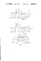
- FIG. 1 is a schematic side view of the present invention
- FIGS. 2A and 2B are fragmentary, schematic, side elevational views of a vehicle recovery unit according to the present invention, showing the unit engaging the ground prior to the lifting of a vehicle to be recovered;
- FIG. 2C is a schematic view, partly in broken lines, and partly in cross-section taken along line 2c-2c in FIG. 1 and viewed in the direction of the arrows, showing the piston/cylinder arrangements disposed adjacent and beyond each side of the recovery vehicle.
- a recovery vehicle 1 upon which is mounted a vehicle recovery unit 2 according to the present invention, upon which vehicle recovery unit 2 is mounted a vehicle to be towed, in this case a lorry 3.
- the recovery vehicle 1 is a tractor unit, of the type used for towing containers such as are used in articulated lorries.
- the tractor unit comprises a front cab (not shown), front axle bearing wheels (not shown), a rear axle 4, bearing wheels 5 and a fifth wheel 6 mounted towards the rear of the recovery vehicle.
- the vehicle recovery unit 2 is mounted on the fifth wheel 6 by means of a standard connection, which standard connection allows the vehicle recovery unit 2 to pivot in the horizontal plane around axis 7 and pivot in the vertical plane around pivot point 8.
- the vehicle recovery unit 2 comprises a first boom 9 which is mounted on the fifth wheel 6 and extends beyond the rear of the vehicle 1. Behind the rear of the vehicle 1 the boom 9 is angled down into a section 10 which extends towards the ground at an angle of approximately 80° to the main part of the boom 9. At the end of the section 10 of the first boom 9 is located a second boom 11. This second boom 11 is pivotally mounted, on the end of section 10, about pivot point 12. A piston and cylinder arrangement 13 connects the horizontal section of the first boom 9 with the one end of the second boom 11 which is nearest the vehicle 1. Within the other end of the second boom 11 is slidably mounted a telescopic extension 14.
- securing holes 15 and the telescopic extension 14 may be secured within the second boom 11 by means of a pin 16 which is extended through second boom 11 and an appropriate securing hole 15 in order to locate and fix the telescopic extension 14 with respect to the second boom 11.
- the first boom 9 has, located in section 10, securing holes 17 which securing holes 17 are aligned with a suitable hole in the second boom 11 through which a securing pin 18 may be passed. In this way, when the vehicle 3 to be towed has been lifted off the ground into a suitable towing position, the second boom 11 may be secured in position with respect to the first boom 9 by means of a pin 18 located through the second boom 11 and the securing holes 17.
- a second cylinder and piston arrangement 19 Located on the first boom 9 between the fifth wheel 6 and the pivotally mounted cylinder and piston arrangement 13 is a second cylinder and piston arrangement 19.
- the piston 20 comprises a bearing foot.
- This bearing foot 31 is movable from the position shown in FIG. 1 to position A, shown by dotted lines in FIG. 1, when necessary.
- the cylinder and piston arrangement 19 may further be extended away from the boom 9, in a normal direction to the longitudinal axis of boom 9, to a point where the cylinder and piston arrangement 19 extends beyond the recovery vehicle 1 as shown in FIG. 1C. In this position, extension legs shown by dotted position B in FIGS. 1 and 2C may be secured to the bearing foot 31 to provide legs, upon which the vehicle recovery unit 2 may rest when the recovery vehicle 1 has been released from the unit 2.
- the lorry 3, which is to be towed by the recovery vehicle 1 is mounted upon the vehicle recovery unit 2 by way of attachment means located at the end of the telescopic extension 14 on the second boom 11 of the recovery unit 2.
- the attachment means are adapted to be attached to the chassis 21 of the lorry 3 and also to the axle 22 of the front wheel 23 of the lorry 3.
- the attachment means comprises axle locating yoke 24 which may be used to locate the axle 22 with respect to the telescopic extension 14, axle lock pin 25 which may be extended around the axle 22 to secure the axle with respect to the axle locking yoke 24, and a chain 26 under tension, which chain 26 secures the chassis 21 to the end of the telescopic extension 14.
- a releasably securable compression load bearer 27 is releasably secured to the second boom 11 and bears the load of the front part of the lorry 3 and also fixes the position of the front part of the lorry 3 with respect to the second boom 11.
- the vehicle recovery unit further comprises a transverse boom 28 upon which are mounted hazard, indicator and brake lights, connected to the appropriate electrical circuits of the recovery vehicle and within which boom 28 is located a tool storage space.
- the vehicle recovery unit 2 When not in use, the vehicle recovery unit 2 may be left in a suitable place, standing freely on extension legs positioned as shown by dotted lines B in FIGS. 1 and 2C.
- any appropriate tractor unit may be used as a recovery vehicle 1 and may be backed towards the recovery unit 2 until the fifth wheel 6 of the tractor unit 1 engages with the recovery unit 2.
- the recovery unit 2 may then be secured to the tractor unit 1, often by means of mere insertion of a king pin along axis 7 of the boom 9 and the fifth wheel 6.
- the second boom 11 When the tractor unit is travelling to the vehicle to be recovered, the second boom 11 is pivoted about the pivot point 12 by means of full extension of the piston and cylinder arrangement 13, so that the telescopic attachment 14 is pointing directly upwards and the second boom 11 is flush with the section 10 of the the boom 9, thus making the vehicle recovery unit 2 more compact. Also when travelling without towing a vehicle, the cylinder piston arrangement 19 is retracted towards the boom 9 and the bearing foot 31 is extended downwardly to the position shown in the figure where it contacts the rear of the tractor unit 1, thereby preventing the recovery unit 2 from pivoting downwardly about the point 8 and hitting the ground. When not in use, the compression load bearer 27, the locking pin 25 and the chain 26 are released from the recovery unit 2 and stored in appropriate spaces in transverse boom 28.
- the cylinder piston arrangement 13 is retracted and the second boom 11 is pivoted about point 12 until the centre line of the second boom 11 is substantially parallel with the ground.
- the telescopic extension 14 is then slid out of the second boom 11 until the distance between the axle locating yoke 24 and the section 10 of the first boom 9 is slightly greater than the distance between the axle 22 of the lorry 3 and the front bumper 29 of the lorry 3.
- the recovery vehicle 1 is then reversed towards the lorry 3 to move the telescopic extension 14 beneath the lorry 3, to a point where the axle locating yoke 24 approximately corresponds to the position of axle 22.
- the bearing foot 31 is raised into cylinder 19 to position A shown in FIG. 1, so that the vehicle recovery unit 2 pivots about the pivot point 8 and the second boom 11 contacts the ground.
- the lorry 3 is then lifted to a position where it may be secured and its position fixed with respect to the second boom 11.
- the piston and cylinder arrangement 13 is expandjed, causing the telescopic extension 14, which has been secured with respect to boom 11 by the location of the pin 16 in a appropriate securing hole 15, to move upwards towards the chassis 21 of the lorry 3.
- the axle locating yoke 24 contacts the axle 22, the telescopic extension 14 will start to force the axle 22, and thus the front end of the lorry 3, away from the ground.
- end portion 30 of the second boom 11, to which end portion 30 the piston and cylinder arrangement 13 is attached is contacted against the ground so as to use the ground as a fulcrum for the lever comprising the telescopic extension 14 and the second boom 11 as best shown in FIGS. 1A and 1B.
- the compression load bearer 27 is mounted on the second boom 11 and the chain 26 is located around the end of the telescopic extension 14 and the chassis 21 of the lorry 3 and secured there.
- the lorry 3 is then lifted to a towing position. This occurs by means of retracting the piston and cylinder arrangement 13, thus lifting end 30 of the second boom 11 away from the ground.
- the lever, formed by the second boom 11 and telescopic extension 14, will pivot, about the end of the compression load bearer 27 which contacts the chassis 21 of the lorry 3, so as to move the end of telescopic extension 14, remote from second boom 11, away from the chassis 21 and thus cause the chain 26 to be tensioned.
- the locking pin 25 may be located about the front axle 22 of the lorry 3 to further secure the telescopic extension 14 to the lorry 3.
- the second boom 11 is pivoted about the point 12 by the contraction of the piston and cylinder arrangement 13, such movement is accommodated by the first boom 9, pivoting about the pivot point 8 on the fifth wheel 6 of the tractor unit 1, so as to move the first boom 9, and thus the second boom 11, upwardly, away from the ground, and so lift the lorry 3 away from the ground into a suitable towing position.
- the position of the second boom 11 is fixed with respect to the first boom 9 by means of securing a pin 18 through the second boom 11 and through an appropriate securing hole 17 located in the section 10 of the first boom 9. In this state, the lorry 3 may be towed away by recovery vehicle 1.
- the piston and cylinder arrangement 19 may be moved normally to the longitudinal axis of the boom 9, to a point which extends beyond the sides of the tractor unit 1.
- the bearing foot 31 may be lowered to the position shown in FIGS. 1 nd 2C and the extension shown by dotted lines B in FIGS. 1 and 2C may be added to the bearing foot 31.
- the apparatus formed by the vehicle recovery unit 2 and the lorry 3 is stabilised at two points, by the rear wheels of the lorry 3 and by the legs represented by B in FIGS. 1 and 2C.
- the fifth wheel 6 may be released from the first boom 9 and the tractor unit 1 may be driven away to leave the vehicle recovery unit 2 standing on the legs B and stabilised by the back wheels of the lorry 3.
- the tractor unit 1 need not necessarily be out of use until such time as the lorry 3 is moved and thus the tractor unit 1 may be disconnected from the vehicle recovery unit 2 at any time.
- the presence of the legs B enable a tractor unit to be driven into a position where the vehicle recovery unit 2 may be mounted upon a tractor unit 1 easily and quickly.
- the weight of the lorry 3 is transferred by means of the first boom 9 and the second boom 11 to the pivot point 8 of the fifth wheel 6. and thus onto the tractor unit 1 at a point between the rear and front axles, thereby spreading the weight of lorry 3 across the whole of tractor unit 1 and so not overloading the rear axle 4 of the tractor unit 1. Furthermore, the turning ability of the combined recovery vehicle 1, the vehicle recovery unit 2 and the lorry 3 is improved because the vehicle recovery unit 2 is securely fastened to the lorry 3, so as to allow no movement therebetween. Thus, the combination of the vehicle recovery unit 2 and lorry 3 pivots solely about the axis 7 and the pivot point 8 of the fifth wheel 6 of the tractor unit 1, thus allowing for greater turning ability of the apparatus.
Landscapes
- Engineering & Computer Science (AREA)
- Transportation (AREA)
- Mechanical Engineering (AREA)
- Chemical & Material Sciences (AREA)
- Combustion & Propulsion (AREA)
- Health & Medical Sciences (AREA)
- Public Health (AREA)
- Agricultural Machines (AREA)
- Vehicle Cleaning, Maintenance, Repair, Refitting, And Outriggers (AREA)
- Catching Or Destruction (AREA)
Applications Claiming Priority (2)
| Application Number | Priority Date | Filing Date | Title |
|---|---|---|---|
| GB8628640 | 1986-12-01 | ||
| GB08628640A GB2198401A (en) | 1986-12-01 | 1986-12-01 | Vehicle recovery unit |
Publications (1)
| Publication Number | Publication Date |
|---|---|
| US4842472A true US4842472A (en) | 1989-06-27 |
Family
ID=10608223
Family Applications (1)
| Application Number | Title | Priority Date | Filing Date |
|---|---|---|---|
| US07/126,148 Expired - Fee Related US4842472A (en) | 1986-12-01 | 1987-11-30 | Vehicle recovery unit |
Country Status (4)
| Country | Link |
|---|---|
| US (1) | US4842472A (fr) |
| EP (1) | EP0270334A3 (fr) |
| DE (1) | DE270334T1 (fr) |
| GB (1) | GB2198401A (fr) |
Cited By (14)
| Publication number | Priority date | Publication date | Assignee | Title |
|---|---|---|---|---|
| US5039272A (en) * | 1988-02-05 | 1991-08-13 | Century Wrecker Corporation | Safety latch and line system for towing vehicles |
| US5163803A (en) * | 1991-03-15 | 1992-11-17 | Tru-Hitch, Incorporated | Truck towing boom |
| US5249911A (en) * | 1991-03-15 | 1993-10-05 | Tru-Hitch, Incorporated | Truck towing boom |
| US5823735A (en) * | 1997-02-14 | 1998-10-20 | Kooima; Roger | Attaching a wheel lift apparatus to a road tractor |
| US20080157506A1 (en) * | 2006-12-29 | 2008-07-03 | Schuettenberg Donald W | Method For Securing Saddlemount To Vehicle |
| US20080219828A1 (en) * | 2006-12-29 | 2008-09-11 | Donald Schuettenberg | Method for securing saddlemount to vehicle |
| US20120045307A1 (en) * | 2006-06-06 | 2012-02-23 | Watkins Doyle E | Universal folding boom trailer |
| US8371599B2 (en) | 2010-12-14 | 2013-02-12 | L. Thomas Duvall | Truck towing system and assembly |
| US8622413B2 (en) | 2006-08-09 | 2014-01-07 | Atc Transportation Llc | Front tow extended saddle |
| US20140339792A1 (en) * | 2006-08-09 | 2014-11-20 | Atc Transportation Llc | Front tow extended saddle |
| US10773762B1 (en) * | 2018-12-28 | 2020-09-15 | Ironman FFB, LLC | Forward facing vehicle transport apparatus |
| US10773631B1 (en) * | 2018-12-28 | 2020-09-15 | Ironman FFB, LLC | Forward facing vehicle transport and return transport vehicle combination |
| US10807425B1 (en) * | 2020-03-26 | 2020-10-20 | Pro-Tote Systems, Inc. | Towing device |
| US20210347419A1 (en) * | 2020-05-06 | 2021-11-11 | Charles Watson | 5th Wheel Towing Attachment |
Families Citing this family (5)
| Publication number | Priority date | Publication date | Assignee | Title |
|---|---|---|---|---|
| GB2238773B (en) * | 1989-12-05 | 1993-11-17 | Eka Ltd | A recovery vehicle |
| FI102362B (fi) * | 1995-11-14 | 1998-11-30 | Kouvolan Sun Filter Oy | Hinauslaite |
| US5984616A (en) * | 1996-11-21 | 1999-11-16 | Prime Technologies, Inc. | Variable pivot towing device |
| RU2121937C1 (ru) * | 1998-01-08 | 1998-11-20 | Военная академия бронетанковых войск | Способ буксирования танков и устройство для его осуществления |
| RU2185971C1 (ru) * | 2001-03-06 | 2002-07-27 | Общевойсковая Академия Вооруженных Сил Российской Федерации | Способ буксирования гусеничных легкобронных объектов |
Citations (15)
| Publication number | Priority date | Publication date | Assignee | Title |
|---|---|---|---|---|
| GB933792A (en) * | 1960-09-09 | 1963-08-14 | Yale & Towne Mfg Co | Pallet handling attachment for industrial lift trucks |
| GB1288444A (fr) * | 1969-04-26 | 1972-09-06 | ||
| GB1355285A (en) * | 1972-01-31 | 1974-06-05 | Taskers Trailers Ltd | Trailer vehicles |
| US3951280A (en) * | 1974-11-20 | 1976-04-20 | John Ratcliff (Tail Lifts) Limited | Vehicle-transporting apparatus |
| US4149643A (en) * | 1977-10-03 | 1979-04-17 | Skala Kent D | Truck tow lift |
| US4152006A (en) * | 1977-09-26 | 1979-05-01 | Dunlap Ward W | Towing apparatus |
| GB2061193A (en) * | 1979-08-14 | 1981-05-13 | Eka Recovery Vehicles Gb Ltd | Recovery vehicle |
| US4383793A (en) * | 1981-02-26 | 1983-05-17 | Chromalloy American Corporation | Tractor implement mount |
| GB2120620A (en) * | 1982-05-26 | 1983-12-07 | Mora Hydraulics Ab | A breakdown recovery vehicle |
| US4509768A (en) * | 1982-05-24 | 1985-04-09 | Karl Kassbohrer Fahrezeugwerke Gmbh | Vehicle with detachable implement |
| US4611968A (en) * | 1984-12-24 | 1986-09-16 | Dover Corporation | Lifting and towing apparatus for large vehicles |
| US4634447A (en) * | 1982-09-09 | 1987-01-06 | Terumo Kabushiki Kaisha | Method for manufacturing artificial organ |
| US4700852A (en) * | 1984-07-17 | 1987-10-20 | Mora Hydraulics Aktiebolag | Recovery vehicle device |
| US4708358A (en) * | 1986-07-11 | 1987-11-24 | Mgs, Inc. | Disabled truck tractor recovery unit |
| US4761111A (en) * | 1981-09-18 | 1988-08-02 | Brown Andrew M | Automobile lifting and towing equipment |
Family Cites Families (5)
| Publication number | Priority date | Publication date | Assignee | Title |
|---|---|---|---|---|
| GB1499871A (en) * | 1973-10-08 | 1978-02-01 | Taskers Trailers Ltd | Swan neck trailers |
| US3888369A (en) * | 1974-09-16 | 1975-06-10 | Banks E Kesselring | Vehicle tow rig |
| GB1583861A (en) * | 1977-06-17 | 1981-02-04 | Watson D | Flat-bed trailers |
| US4543030A (en) * | 1983-12-30 | 1985-09-24 | Hawkins Wallace H | Fifth wheel wrecker hoist |
| US4640660A (en) * | 1984-02-20 | 1987-02-03 | Eka Group Ltd. | Recovery and towing vehicle |
-
1986
- 1986-12-01 GB GB08628640A patent/GB2198401A/en active Pending
-
1987
- 1987-11-30 DE DE198787310553T patent/DE270334T1/de active Pending
- 1987-11-30 US US07/126,148 patent/US4842472A/en not_active Expired - Fee Related
- 1987-11-30 EP EP87310553A patent/EP0270334A3/fr not_active Withdrawn
Patent Citations (15)
| Publication number | Priority date | Publication date | Assignee | Title |
|---|---|---|---|---|
| GB933792A (en) * | 1960-09-09 | 1963-08-14 | Yale & Towne Mfg Co | Pallet handling attachment for industrial lift trucks |
| GB1288444A (fr) * | 1969-04-26 | 1972-09-06 | ||
| GB1355285A (en) * | 1972-01-31 | 1974-06-05 | Taskers Trailers Ltd | Trailer vehicles |
| US3951280A (en) * | 1974-11-20 | 1976-04-20 | John Ratcliff (Tail Lifts) Limited | Vehicle-transporting apparatus |
| US4152006A (en) * | 1977-09-26 | 1979-05-01 | Dunlap Ward W | Towing apparatus |
| US4149643A (en) * | 1977-10-03 | 1979-04-17 | Skala Kent D | Truck tow lift |
| GB2061193A (en) * | 1979-08-14 | 1981-05-13 | Eka Recovery Vehicles Gb Ltd | Recovery vehicle |
| US4383793A (en) * | 1981-02-26 | 1983-05-17 | Chromalloy American Corporation | Tractor implement mount |
| US4761111A (en) * | 1981-09-18 | 1988-08-02 | Brown Andrew M | Automobile lifting and towing equipment |
| US4509768A (en) * | 1982-05-24 | 1985-04-09 | Karl Kassbohrer Fahrezeugwerke Gmbh | Vehicle with detachable implement |
| GB2120620A (en) * | 1982-05-26 | 1983-12-07 | Mora Hydraulics Ab | A breakdown recovery vehicle |
| US4634447A (en) * | 1982-09-09 | 1987-01-06 | Terumo Kabushiki Kaisha | Method for manufacturing artificial organ |
| US4700852A (en) * | 1984-07-17 | 1987-10-20 | Mora Hydraulics Aktiebolag | Recovery vehicle device |
| US4611968A (en) * | 1984-12-24 | 1986-09-16 | Dover Corporation | Lifting and towing apparatus for large vehicles |
| US4708358A (en) * | 1986-07-11 | 1987-11-24 | Mgs, Inc. | Disabled truck tractor recovery unit |
Cited By (29)
| Publication number | Priority date | Publication date | Assignee | Title |
|---|---|---|---|---|
| US5039272A (en) * | 1988-02-05 | 1991-08-13 | Century Wrecker Corporation | Safety latch and line system for towing vehicles |
| US5163803A (en) * | 1991-03-15 | 1992-11-17 | Tru-Hitch, Incorporated | Truck towing boom |
| US5249911A (en) * | 1991-03-15 | 1993-10-05 | Tru-Hitch, Incorporated | Truck towing boom |
| US5823735A (en) * | 1997-02-14 | 1998-10-20 | Kooima; Roger | Attaching a wheel lift apparatus to a road tractor |
| US6036428A (en) * | 1997-02-14 | 2000-03-14 | Kooima; Roger | System for attaching a towing apparatus to a road tractor |
| US8613583B1 (en) * | 2006-06-06 | 2013-12-24 | Wastow Enterprises, Llc | Universal folding boom trailer |
| US20120045307A1 (en) * | 2006-06-06 | 2012-02-23 | Watkins Doyle E | Universal folding boom trailer |
| US8348589B2 (en) * | 2006-06-06 | 2013-01-08 | Wastow Enterprises LLC | Universal folding boom trailer |
| US10926593B2 (en) | 2006-08-09 | 2021-02-23 | Atc Transportation Llc | Front tow extended saddle |
| US11613148B2 (en) | 2006-08-09 | 2023-03-28 | Atc Transportation Llc | Front tow extended saddle |
| US10179532B2 (en) | 2006-08-09 | 2019-01-15 | Atc Transportation Llc | Front tow extended saddle |
| US9381958B2 (en) * | 2006-08-09 | 2016-07-05 | Atc Transportation Llc | Front tow extended saddle |
| US20140339792A1 (en) * | 2006-08-09 | 2014-11-20 | Atc Transportation Llc | Front tow extended saddle |
| US8622413B2 (en) | 2006-08-09 | 2014-01-07 | Atc Transportation Llc | Front tow extended saddle |
| US20140217699A1 (en) * | 2006-08-09 | 2014-08-07 | Atc Transportation Llc | Front tow extended saddle |
| US9114677B2 (en) * | 2006-08-09 | 2015-08-25 | Atc Transportation Llc | Front tow extended saddle |
| US7611159B2 (en) * | 2006-12-29 | 2009-11-03 | Atc Leasing Company, Llc | Method for securing saddlemount to vehicle |
| US7637524B2 (en) * | 2006-12-29 | 2009-12-29 | ATC Leasing Co., LLC | Method for securing saddlemount to vehicle |
| US20080219828A1 (en) * | 2006-12-29 | 2008-09-11 | Donald Schuettenberg | Method for securing saddlemount to vehicle |
| US20080157506A1 (en) * | 2006-12-29 | 2008-07-03 | Schuettenberg Donald W | Method For Securing Saddlemount To Vehicle |
| US8876139B2 (en) | 2010-12-14 | 2014-11-04 | Truckmovers.Com, Inc. | Truck towing system and assembly |
| US8371599B2 (en) | 2010-12-14 | 2013-02-12 | L. Thomas Duvall | Truck towing system and assembly |
| US9636957B2 (en) | 2010-12-14 | 2017-05-02 | Truckmovers.Com, Inc. | Truck towing system and assembly |
| US10773762B1 (en) * | 2018-12-28 | 2020-09-15 | Ironman FFB, LLC | Forward facing vehicle transport apparatus |
| US10773631B1 (en) * | 2018-12-28 | 2020-09-15 | Ironman FFB, LLC | Forward facing vehicle transport and return transport vehicle combination |
| US11702163B2 (en) * | 2018-12-28 | 2023-07-18 | Ironman FFB, LLC | Forward facing vehicle transport system |
| US10807425B1 (en) * | 2020-03-26 | 2020-10-20 | Pro-Tote Systems, Inc. | Towing device |
| US20210347419A1 (en) * | 2020-05-06 | 2021-11-11 | Charles Watson | 5th Wheel Towing Attachment |
| US12370967B2 (en) * | 2020-05-06 | 2025-07-29 | Charles Watson | 5th wheel towing attachment |
Also Published As
| Publication number | Publication date |
|---|---|
| GB8628640D0 (en) | 1987-01-07 |
| GB2198401A (en) | 1988-06-15 |
| EP0270334A3 (fr) | 1988-10-12 |
| DE270334T1 (de) | 1988-10-13 |
| EP0270334A2 (fr) | 1988-06-08 |
Similar Documents
| Publication | Publication Date | Title |
|---|---|---|
| US4842472A (en) | Vehicle recovery unit | |
| US5984614A (en) | Apparatus for retrieving and transporting disabled vehicles | |
| US7607546B1 (en) | Hitch mounted hoist assembly | |
| US5803699A (en) | Apparatus and method for loading and unloading containers | |
| US5326215A (en) | Universal vehicular recovery and towing platform | |
| US12246783B2 (en) | Self-storing sliding hydraulic booster for trailer | |
| US4840534A (en) | Automobile lift and tow hoist | |
| US6942443B2 (en) | Wheel-lift device with tongue for towing vehicles | |
| CA1106830A (fr) | Stabilisateur pour vehicule | |
| US4383807A (en) | Towing vehicle, boom, winching and lifting apparatus | |
| US2967720A (en) | Detachable gooseneck for trailers and the like | |
| US3897879A (en) | Vehicle towing apparatus | |
| US4200305A (en) | Trailer assembly for carrying overwidth loads | |
| US5845920A (en) | Apparatus for towing a disabled truck tractor | |
| US3724697A (en) | Truck having a vertically displaceable carrying frame | |
| US4578014A (en) | Automobile tray trailer | |
| US4569422A (en) | Stiff leg attachment for wrecker | |
| CA1042846A (fr) | Moyen de transport pour engin de chantier | |
| US3545635A (en) | Preload for hauling logs and the like | |
| US7448839B2 (en) | Vehicular towing apparatus using air lift | |
| US5601303A (en) | Combine trailer | |
| US5215425A (en) | Tractor towing apparatus | |
| US5988664A (en) | Apparatus for towing a disabled truck tractor | |
| GB2061193A (en) | Recovery vehicle | |
| US7841604B2 (en) | Detachable trailing tag axle |
Legal Events
| Date | Code | Title | Description |
|---|---|---|---|
| AS | Assignment |
Owner name: PCM (LONG BUCKBY) ENGINEERING LTD., THE WHAR, LONG Free format text: ASSIGNMENT OF ASSIGNORS INTEREST.;ASSIGNOR:PLANT, JOHN D.;REEL/FRAME:004985/0253 Effective date: 19871127 Owner name: PCM (LONG BUCKBY) ENGINEERING LTD., UNITED KINGDOM Free format text: ASSIGNMENT OF ASSIGNORS INTEREST;ASSIGNOR:PLANT, JOHN D.;REEL/FRAME:004985/0253 Effective date: 19871127 |
|
| AS | Assignment |
Owner name: P.C.M. (LONG BUCKBY) LTD., UNITED KINGDOM Free format text: RERECORD TO CORRECT THE ASSIGNEE OF A PREVIOUSLY RECORDED DOCUMENT;ASSIGNOR:PLANT, JOHN DOUGLAS;REEL/FRAME:005240/0453 Effective date: 19871127 |
|
| FPAY | Fee payment |
Year of fee payment: 4 |
|
| REMI | Maintenance fee reminder mailed | ||
| LAPS | Lapse for failure to pay maintenance fees | ||
| FP | Expired due to failure to pay maintenance fee |
Effective date: 19970702 |
|
| STCH | Information on status: patent discontinuation |
Free format text: PATENT EXPIRED DUE TO NONPAYMENT OF MAINTENANCE FEES UNDER 37 CFR 1.362 |