US4862376A - Bill of material interface to CAD/CAM environment - Google Patents
Bill of material interface to CAD/CAM environment Download PDFInfo
- Publication number
- US4862376A US4862376A US07/113,837 US11383787A US4862376A US 4862376 A US4862376 A US 4862376A US 11383787 A US11383787 A US 11383787A US 4862376 A US4862376 A US 4862376A
- Authority
- US
- United States
- Prior art keywords
- bill
- materials
- image
- text
- cad
- Prior art date
- Legal status (The legal status is an assumption and is not a legal conclusion. Google has not performed a legal analysis and makes no representation as to the accuracy of the status listed.)
- Expired - Lifetime
Links
Images




Classifications
-
- G—PHYSICS
- G06—COMPUTING OR CALCULATING; COUNTING
- G06Q—INFORMATION AND COMMUNICATION TECHNOLOGY [ICT] SPECIALLY ADAPTED FOR ADMINISTRATIVE, COMMERCIAL, FINANCIAL, MANAGERIAL OR SUPERVISORY PURPOSES; SYSTEMS OR METHODS SPECIALLY ADAPTED FOR ADMINISTRATIVE, COMMERCIAL, FINANCIAL, MANAGERIAL OR SUPERVISORY PURPOSES, NOT OTHERWISE PROVIDED FOR
- G06Q10/00—Administration; Management
- G06Q10/08—Logistics, e.g. warehousing, loading or distribution; Inventory or stock management
- G06Q10/087—Inventory or stock management, e.g. order filling, procurement or balancing against orders
- G06Q10/0875—Itemisation or classification of parts, supplies or services, e.g. bill of materials
-
- G—PHYSICS
- G06—COMPUTING OR CALCULATING; COUNTING
- G06F—ELECTRIC DIGITAL DATA PROCESSING
- G06F30/00—Computer-aided design [CAD]
-
- G—PHYSICS
- G06—COMPUTING OR CALCULATING; COUNTING
- G06T—IMAGE DATA PROCESSING OR GENERATION, IN GENERAL
- G06T17/00—Three-dimensional [3D] modelling for computer graphics
Definitions
- the present invention generally relates to a computer based project management system and, more particularly, to a system, based on a top down functional approach to hardware product design, which provides an interface for importing an indented bill of materials into a CAD/CAM environment as an aid to the product designer in the detailed design phase of the product.
- a PERT chart is one that resembles a flow chart showing predecessor and successor tasks of a project and the critical path.
- PERT/CPM models are known and have been used for many years by many large corporations for project management. Such project management tools were first implemented on main frame computers and then on mini computers, equipment which was readily available to large corporations but not to small corporations and firms. More recently, various project management software products have been developed for micro or so-called personal computers.
- An example of a project management tool which was originally written as a mainframe program and later rewritten as a personal computer program is Plantrac, published by Computerline, Inc. This program was originally written in England for the construction industry and later imported to the U.S.A. The first project management tool written specifically for the personal computer was called the Harvard Project Manager, now published by Software Publishing Corp. There are now over one hundred project manager applications written for personal computers.
- This top-down design approach has significant advantages over the traditional approach to design of a new product.
- the Schmidtberg and Yerry implementation is in the environment of a CAD/CAM system which assumes a different focus and a high degree of sophistication in using computers for design on the part of the user. What is needed is a simpler to use system which takes advantage of the top-down design approach.
- Such a system should also be capable of importing the functional and detailed design specifications and manufacturing/process details as available into the CAD/CAM environment as an aid to the product designer in the detailed design of the product.
- a sketch sheet approach on a computer display is used to enter the functional design of a product.
- the user needs to key in only part descriptions, and the system automatically draws a hierarchical tree structure on the computer display. The user is then prompted to consider, part by part, all of the parts in the product. A series of menus or "action bars” pop-up and guide the user through manufacturing planning for that part.
- the process begins by producing a functional sketch of the product design.
- This sketch is in the form of a hierarchical tree structure, thereby encouraging the top-down design approach.
- the system queries or prompts the user for component parts of the product, and as the query process progresses, the tree structure is created on the computer screen for the user to view.
- the component specifications are captured in a table in the database.
- the system can automatically generate an indented bill of materials based on the data currently stored in the table.
- Each component is assigned an identification number, and this number is used to access the data in the table.
- the product designer is aided in implementing early manufacturing involvement, or the integration of the design process with manufacturing and other production-related concerns.
- the designer is prompted to enter engineering planning and manufacturing data for each item in the product structure, thus introducing a third dimension to the hierarchical tree structure.
- This third dimension serves several purposes.
- the engineering and manufacturing data can be manipulated to produce needed estimates and schedules for the designer.
- the manufacturing data of interest falls under four categories: (1) information which assists in planning the manufacture of the product, (2) information which assists in producing a cost estimate of the product, (3) information which assists in generating a product release schedule, and (4) information which will assist a CAD/CAM designer in locating similar items.
- the designer then has the option to use the similar design, avoiding another design effort, or to use the existing design as a template to modify or for other guidance in preparing the new design.
- the indented bill of materials when used in the CAD/CAM environment, is used to guide the designer in detailed design.
- the designer is able to copy and place items from the bill of materials in the drawing itself rather than keying the item names and numbers manually.
- the designer can access standard drawings in a database by using the item numbers identified in the bill of materials.
- FIG. 1 is a system block diagram showing the functional requirements for implementing the automated bill of materials which is used by the present invention
- FIG. 2 is a pictorial representation of a hierarchical tree structure showing the functional representation of the components of a new product
- FIG. 3 is a table illustrating the logical organization of the database for the hierarchical tree structure shown in FIG. 2;
- FIG. 4. is a generalized illustration of an indented bill of material produced by the system from the relational database table shown in FIG. 3;
- FIG. 5 is a screen illustrating the computer display of a hierarchical tree structure generated by the system for a planned product under design
- FIG. 6 is a screen illustrating the computer display of early manufacturing involvement data for one component of the structure shown in FIG. 5;
- FIG. 7 is a screen illustrating the computer display of early manufacturing involvement data for one component with default data as entered by the system
- FIG. 8 is a flow chart showing the logic of the conceptual design tool
- FIG. 9 is a flow chart showing the logic of the query session during which the hierarchical tree of FIG. 2 and the table of FIG. 3 is built;
- FIG. 10 is a flow chart showing the logic of the generation of the indented bill of materials shown in FIG. 4 using the table in the database;
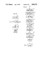
- FIGS. 11A, 11B and 11C taken together, are a flow chart showing the logic of the bill of materials interface to a CAD/CAM environment.
- FIG. 12 is a flow chart showing in more detail the draw function of the interface shown in FIG. 11C.
- the database 10 could be any of several products currently available, but for purposes of the preferred embodiment, IBM's DATABASE 2 (DB2) is used.
- DB2 is a relational database management system, but it will be understod by those skilled in the art that other databases, including hierarchical databases, could be used.
- the query system 12 could be an expert system, but for purposes of the preferred embodiment, IBM's Restructured Extended Executor (REXX) language is used.
- REXX Restructured Extended Executor
- the user 14 is first queried on the functional product structure by the query system 12, and in response to the user input, the database 10 captures the structure in a table.
- the query session begins by prompting the user to input the name of the product.
- the product might be a new lawnmower, for example, and the user would simply type in "LAWNMOWER".
- the query system asks the user to list the major components of the product. In the case of the lawnmower, this might be a handle, a grass catcher, a motor cover, a blade, wheels, documentation, electronics, and a battery. These would be individually entered by the user, in no particular order, in response to a prompt to enter the next component or indicate that there are no more major components by entering "END" or pressing a designated key.
- the user enters "END" causing the query system to examine the subcomponents of the major components that have been entered.
- the query system 12 would prompt the user 14 to enter the components of the handle. These components might be an upper handle assembly with controls and a lower handle assembly which attaches to the lawnmower frame.
- the user enters "END", causing the query system to next prompt the user to enter the components of the grass catcher, and so on. The process continues until the user has entered all the components of the new product to a level of detail desired, at least for the time being. It should be understood, however, that the user can return to the design session at any time and add more detail and/or change earlier input component data.
- the components entered by the user 14 are captured in a table of the relational database 10 and a functional hierarchical tree of the structure 16 is generated on the computer screen.
- a generalized example of this hierarchical tree structure is shown in FIG. 2 of the drawings. If a subassembly appears more than one time in a product, the subassembly also appears multiple times in the tree.
- the tree structure has three levels. It may have as few as two levels and, within practical limits, an indefinite number of levels depending on the product and the level of detail required to define that product. In a specific embodiment of the invention, up to thirty leveles of the tree structure are allowed. Experience indicates that this is sufficient for all but the most complex of products.
- the database 10 captures the component information from the user input in a table having the form shown in FIG. 3. Comparing this table to the hierarchical tree of FIG. 2, it will be observed that under the heading "ITEM" the numeral 1 is listed four times with the numerals 2, 3, 4, and 5 immediately to the right. This is followed by the numeral 2 listed twice with the numerals 6 and 7 immediately to the right.
- the table shown in FIG. 3 directly describes the hierarchical tree structure from which the graphical representation illustrated in FIG. 2 is generated for display on the computer screen. The user views this tree structure and can check it for correctness as it is generated and after the product is established by the end of the query session.
- FIG. 3 shows the logical storage of the product data structure
- FIGS. 2 and 4 show two, alternative representations of the data.
- This bill of material is built by accessing the database table for the product. The table is accessed by item number. In the top level, item 1 is not indented.
- the second level items 2, 3, 4, and 5 are indented one space.
- the third level items 6, 7, 8, 9, and 10 are each indented two spaces, and so on.
- the application code follows the item hierarchy as follows: Item 1 appears on the top line. Item 2 appears on the second line. Then the database is searched for item 2 antecedents. Items 6 and 7 would be found. Item 6 would then appear on the third line. The database is then searched for item 6 antecedents. In this example, none would be found, and item 7 would then appear on the fourth line. Again, the database is searched for item 7 antecedents, but again none would be found, and item 3 would appear on the fifth line. The remaining items are similarly processed until a complete bill of material is produced.
- FIG. 6 shows a screen from a computer display which would appear when the user selects, for example, BATTERY as the object and chooses the action "DETAIL".
- the design engineer keys in known manufacturing data using this screen.
- the designer intends to use an "off the shelf” battery to be purchased complete from Sears.
- the user can then choose to have default values supplied from the relational database based on known item attributes.
- the user selects the action "DEFAULT", and the screen shown in FIG. 7 is displayed.
- the method by which the relational database can access these defaults is by accessing the table in which the user input data was captured during the query session. More specifically, the items in the table are accessed by item numbers and these numbers, in turn, are used as an index to access the default values for items, these values having been previously stored in the database.
- the screen shown in FIG. 7 displays the resultant default values, marked by an asterisk.
- the system has generated an item number, A000. From the position of the item within the tree, the system has determined that it is a Main Assembly. The full name of the vendor, Sears Roebuck, Inc., is inserted. The process by which the battery is incorporated into the product is assembly. Tooling leadtime defaults to zero since the item is purchased complete off the shelf. The cost per battery, based on actuals, is $15.00.
- An item classification, or group technology classification is system generated based on the function of this item within the product and the fact that it is purchased complete. This item classification code is used in many production planning functions, including scheduling and procurement.
- FIG. 8 there is shown a flow chart of the logic of the conceptual design tool according to the invention implemented in software.
- One of ordinary skill in the art can write source code from this flow chart in any suitable computer language, such as BASIC, Pascal or C, for any desired computer system, such as the IBM Personal System (PS) computers which support those computer languages.
- suitable computer language such as BASIC, Pascal or C
- PS IBM Personal System
- the process begins by inputting the functional structure of the product as indicated by function block 100. This is done during the query session as is described in more detail with respect to FIG. 9.
- the user is prompted to select an item in the structure in function block 102.
- the system provides a pop-up panel for manufacturing details in function block 104. This pop-up panel allows the user to key in known manufacturing information in function block 106.
- the system generates an item number in function block 108. The system then allows the user to choose to access default information in function block 110.
- decision block 112 A test is made in decision block 112 to determine if the user has choosen to access default information. If not, a test is next made in decision block 114 to determine if there are more items for which manufacturing details are to be input. If so, then the process loops back to function block 102.
- test in decision block 112 is positive, that is, the user chooses to access default information
- function block 116 the system accesses the default values in database 10 and inserts those values.
- function block 118 the system generates an item classification code.
- the user is given the option of overriding any of the default data in function block 120.
- a test is made in decision block 122 to determine if the user chooses to override any default data. If so, the system loops back to function block 106 which allows the user to key in known manufacturing data as a typeover of the previously inserted default data; otherwise, the system loops to function block 102 to select the next item in the functional structure of the product.
- the test in decision block 114 will be negative, and the process ends.
- FIG. 9 shows in flow chart form the logic of the query system according to the invention.
- the program logic represented by FIG. 9 is what builds the database represented by FIG. 3.
- This flow chart in combination with a dialog system such as IBM's REXX, and a database system, such as IBM's DB2, is sufficient for a programmer of ordinary skill in the art to write the required code to implement the query system.
- function block 22 the user of the system is prompted for the product name.
- the system waits for a user input at decision block 24, and when the product name has been input, the system opens a file in the database with the product name and displays the product name on the computer screen in function block 26.
- l is set to l+1 indicating the next level of components, and the system then prompts the user in function block 30 for the components of the product at this level.
- the inputted component is stored in the data base for that level in function block 34, and the system displays the inputted component on the computer screen at a node of the tree structure in function block 36.
- the system will continue to prompt the user for components after each component is entered by the user until the user presses an END function key which signals an end to the list of components for this level.
- the system tests the user input in decision block 38 for the END function key input. If that key input is not detected, then the system waits for the next user input in decision block 32, and when an input is received, the component is stored in the database table in fucntion block 34 and so forth.
- the system determines in decision block 40 if the last component in the current level of components has been input by the user. If not, the next component inthe current level is highlighted in the displayed tree structure, and the system loops back to function block 30 where the user is again prompted for components of this component. On the other hand, if the last component of the current level of components has been input by the user as detected in decision block 40, the system tests for a user input in decision block 44 to determine if components are to be entered for the next level. This is accomplished by the user pressing a Y key or an N key when prompted for the next level.
- the system loops back to block 28 to index the next level. If on the other hand, the N key is pressed indicating that the user does not at this time wish to input the next level of components or that there is no next level of components to enter, the query process ends.
- FIG. 10 shows how the indented bill of materials is automatically generated from the table in the database which was built during the query session.
- this flow chart shows the logic of the automatic generation of the indented bill of materials, and any programmer skilled in the art with an understanding of database systems such as the IBM DB2 database, can write code to implement the invention from the logic of the flow chart.
- item 1 of level 1 is accessed in function block 48.
- Item 1 is then printed in function block 50, and l and i are then indexed by adding one to each.
- the level and indentation are again indexed backward by subtracting one in block 68.
- a test is then made in decision block 70 to determine if the indentation i is less than or equal to zero. If not, the process loops back to decision block 54; otherwise, the indented bill of materials is complete and the process ends.
- the indented bill of materials is stored in the format of the ANSI (American National Standards Institute) standard X3.122-1986, which is the Computer Graphics Metafile (CGM), although a similar standard could be used.
- CGM Computer Graphics Metafile
- the CGM standard is focused on the generation and transfer of device independent information which is sufficient for a picture to be drawn on a variety of graphics output devices.
- CGM is used to store an image of the structured bill of materials which can be displayed within a variety of CAD/CAM environments. Although it is an image within the CAD/CAM environment, the text characters are CGM primitives which retain their identity as text. These text characters can be manipulated within the CAD/CAM environment, and the bill of material image can be modified.
- Any CAD/CAM system which uses the CGM standard can display the structured bill of material image.
- the bill of material image can be placed on one half of the CAD/CAM screen, or in a window, or on a separate display, or hot-button toggled, depending on the particular hardware being used.
- the designer can then copy the text within the bill of materials and place it on the CAD/CAM drawing. No part number keying is required, reducing the typing the designer needs to do.
- the displayed bill of materials can be used to guide the design drawing in the CAD/CAM environment. Updates to the structured bill of materials displayed on the CAD/CAM terminal can be made in the CAD/CAM environment, as long as the alphanumeric characters are retained as text primitives rather than vectors or pixels (raster fonts). New parts can be inserted, parts can be deleted, quantities can be changed, and the stucture can be changed.
- Inserted parts are indented as appropriate in the image of the bill of materials structure.
- the x-position will be used to determine the level of that part when the bill of materials is stored in the relational database.
- the y-position is used to determine the position of the part relative to other parts (where used information).
- the x and y locations are used to establish needed "parent-child" relationships between parts in the structure and are used to update the relational database.
- the tables in the relational database contain product structure information necessary to either display the structure in the format of a hierachical tree or in the format of an indented bill of materials.
- the updated bill of materials image within the CAD/CAM environment can then be stored in the CGM standard format. In this format, it can be used in the conceptual design tool, or for production planning functions.
- FIGS. 11A, 11B and 11C taken together, show the flow chart of the logic for the interface of the indented bill of material to a CAD/CAM environment according to the invention.
- the flow chart is divided into three environments: the planning environment of FIG. 11A, the interface of FIG. 11B, and the design environment of FIG. 11C.
- the planning environment may be implemented with a personal computer such as an IBM Personal System 2 (PS/2) computer or a mainframe computer.
- PS/2 IBM Personal System 2
- the design environment may be implemented wth standalone work station such as the IBM RT (Risc Technology) PC or a work station connected to a mainframe computer such as an IBM 5080 or the equivalent.
- the key to the interface logic is the use of the ANSI standard CGM, and any programmer familiar with that standard, or a similar standard, can implement the invention from this flow chart.
- the process begins in the planning environment of FIG. 11A by generating the product structure tree in function block 144 and creating the indented bill of materials in function block 146 using the conceptual design tool application. This process has already been described with reference to FIGS. 8, 9 and 10. The planning process continues with the input of manufacturing detail in function block 148.
- the indented bill of materials produced in the planning environment is converted to a CGM graphics standard in FIG. 11B.
- the primitive text file stored in the CGM graphics standard can then be imported and displayed as an image in the design environment in FIG. 11C; that is, the CGM file is imported into a CAD/CAM application.
- the process by which the indented bill of materials is formatted and stored in the CGM graphics standard begins by calling the metafile storage function in function block 152. Using this function, the process begins to create a computer graphics metafile in function block 154. The first step is to print the beginning metafile element in function block 156. Then, the name of the metafile, which is the name of the product being designed bill of materials, is printed in function block 158. The metafile element list is set to be equal to the metafile version of the text in function block 160, and the metafile descriptor is printed in function block 162. The primitive element text is printed in function block 164. This primitive element text is the body of the bill of materials.
- the previously computed indentation and levels of the bill of material are used to compute the x,y coordinates of the text in the metafile.
- the end metafile element is printed in function block 166.
- the CGM file thus created is saved in the database 10 in function block 170.
- the design session begins by splitting the display screen into two windows in function block 172.
- the two windows might be displayed side-by-side with the left window for text and the right window for graphics.
- the two windows do not need to be same size, and the text window might be narrower than the graphics window.
- the CGM metafile in database 10 is retrieved, and in function block 176, this file is loaded into the design application.
- the bill of materials CGM text file is imported into the text window of the display in function block 178. Once displayed, the bill of materials can be used as a design aid, allowing the designer to copy and place item names and numbers from the bill of materials into the drawing itself rather than keying the item names and numbers manually.
- the designer begins the drawing process in the graphics window in function block 180.
- the designer can select item names, tolerances and the like from the bill of materials image in the text window and import those names and tolerances to the graphics window, as indicated in function block 182. In this way, the designer is relieved of the burden of re-keying the text for insertion as legends in the graphics window.
- the process is one in which the designer simply moves the cursor from the graphics window to the text window, and by placing the cursor over the desired text, or at the beginning and end of a block of text, selects the text to be imported to the graphics window. The designer then moves the cursor back to the graphics window and selects the placement location for the text.
- the process can be accomplished in any convenient manner, such as dragging the text, and the particular technique is a matter of design choice to one of ordinary skill in the art.
- the designer can update the bill of materials in the displayed image of the text window by inserting or deleting items as indicated in function block 184.
- the only requirement is that the displayed bill of materials retain its character as text primitives.
- the items that make up the product are drawn in the graphics window as generally indicated by function block 186.
- a feature of the draw function is illustrated in FIG. 12, which is described in more detail hereinafter.
- the bill of materials file is modified, as necessary, in function block 188 and is then stored in a CGM file as illustrated in FIG. 11B.
- the updated bill of materials is in this way returned to database 10.
- the conceptual design tool or other application package can then access the bill of materials from database 10 as indicated in FIG. 11A for use in continued planning activities 149.
- the novelty of this concept is placing an image of the bill of materials into the CAD/CAM environment while retaining its character as text primitives allowing it to be used as an aid in the design process.
- the invention comprises an integral part of a top-down design process that causes the user to plan a proposed product in a hierarchical manner.
- detailed CAD/CAM design can be done using the overall product structure by importing the bill of materials into the CAD/CAM environment.
- modifications to the bill of materials can be made in the CAD/CAM environment and the modified bill of materials then can be moved back to the conceptual design tool for use in the continuing planning process.
- the bill of materials image displayed in the text window of the work station display is used to access standard drawings in a drawing database. It is common in CAD systems to develop, or purchase, a library of standard drawings which may be imported into a current drawing. Architectual CAD systems commonly incorporate standard drawings for wall sections, doors, windows, and the like. The selection of these drawings is typically by inputting the drawing name or by selection from a graphics tablet menu.
- the bill of materials in the text window becomes a menu for selecting standard drawings to aid in the design process.
- These drawings may, in the example of the lawnmower, be various items of hardware such as screws and bolts, wheels, battery, motor and so forth.
- the item or part number of the bill of materials is used to access the standard drawings, thus providing the designer with a custom menu for each product being designed.
- the process begins in decision block 200 where the user input is monitored to detect if an item number has been selected from the bill of materials. When an item number is selected, a determination is made in decision block 202 as to whether the selected item number is in the drawing database. If it is not, then in function block 204 a message is displayed to the user that a drawing for the selected item number does not exist, and the process loops back to decision block 200.
- the drawing is obtained from the database and placed at the current cursor location in the graphics drawing window.
- the user is then given several choices as to what to do with the drawing. A few are shown in the drawing and will serve to illustrate the typical graphic editing functions which may be performed.
- decision block 208 the user is given the option of rotating the drawing image. If this option is chosen, the drawing image is rotated in response to cursor movement, for example, in function block 210.
- decision block 212 the user is given the option of zooming the drawing; i.e., enlarging or reducing the size of the drawing. If this option is chosen, the drawing image is enlarged or reduced in response to the zoom command in function block 214.
- the system monitors the user's input in decision block 216 to determine where the drawing image is to be fixed on the screen. This typically would be indicated by the press of a mouse button or an ENTER key. Until the user command is detected to fix the image on the screen, the system continues to drag the image of the drawing with the cursor in function block 218, and control loops back to decision block 208. However, at such time as the user command is detected, the image is fixed at the location indicated by the current position of the cursor. Then a test is made in decision block 220 to determine if there are more drawings to be made in this session. If not, the CAD session ends; otherwise, control loops back to decision block 200.
- decision block 200 if an item number is not selected from the bill of materials, the user is given the option in decision block 222 of beginning a new drawing. If that option is selected, a graphics package is called in function block 224 for performing the drawing functions.
- the graphics package itself forms no part of the present invention and may be any of several commercially available packages, such as the CADAMTM package sold by IBM Corp.
- the user is given the option of adding this drawing to the database of standard drawings in decision block 226. For example, assume that the user has just generated a handle assembly for the lawnmower and expects that this handle assembly will be used in other models. The user might then want to save the drawing as a standard drawing for later use in another design project. In that case an item or part number is assigned to the drawing in function block 228, and the process then goes to decision block 220. If the user chooses not to add this drawing to the database, the process goes directly to decision block 220.
Landscapes
- Engineering & Computer Science (AREA)
- Physics & Mathematics (AREA)
- Business, Economics & Management (AREA)
- Theoretical Computer Science (AREA)
- General Physics & Mathematics (AREA)
- Economics (AREA)
- Geometry (AREA)
- Operations Research (AREA)
- Quality & Reliability (AREA)
- Accounting & Taxation (AREA)
- General Engineering & Computer Science (AREA)
- Development Economics (AREA)
- Computer Hardware Design (AREA)
- Entrepreneurship & Innovation (AREA)
- Human Resources & Organizations (AREA)
- Evolutionary Computation (AREA)
- Marketing (AREA)
- Finance (AREA)
- Strategic Management (AREA)
- Tourism & Hospitality (AREA)
- General Business, Economics & Management (AREA)
- Computer Graphics (AREA)
- Software Systems (AREA)
- Management, Administration, Business Operations System, And Electronic Commerce (AREA)
- General Factory Administration (AREA)
- Document Processing Apparatus (AREA)
Priority Applications (6)
| Application Number | Priority Date | Filing Date | Title |
|---|---|---|---|
| US07/113,837 US4862376A (en) | 1987-10-28 | 1987-10-28 | Bill of material interface to CAD/CAM environment |
| DE3855756T DE3855756T2 (de) | 1987-10-28 | 1988-09-13 | Schnittstelle für Materialliste für CAD/CAM-Umgebung |
| EP88480027A EP0314595B1 (de) | 1987-10-28 | 1988-09-13 | Schnittstelle für Materialliste für CAD/CAM-Umgebung |
| JP63233854A JPH0673137B2 (ja) | 1987-10-28 | 1988-09-20 | 概念設計ツールとcad/cam環境間に部品表のインターフエイスを与える方法 |
| CA000578217A CA1300274C (en) | 1987-10-28 | 1988-09-23 | Bill of material interface to cad/cam environment |
| BR8805538A BR8805538A (pt) | 1987-10-28 | 1988-10-27 | Interface de relacao de materiais entre um instrumento de projeto conceitual e um ambiente de cad/cam |
Applications Claiming Priority (1)
| Application Number | Priority Date | Filing Date | Title |
|---|---|---|---|
| US07/113,837 US4862376A (en) | 1987-10-28 | 1987-10-28 | Bill of material interface to CAD/CAM environment |
Publications (1)
| Publication Number | Publication Date |
|---|---|
| US4862376A true US4862376A (en) | 1989-08-29 |
Family
ID=22351800
Family Applications (1)
| Application Number | Title | Priority Date | Filing Date |
|---|---|---|---|
| US07/113,837 Expired - Lifetime US4862376A (en) | 1987-10-28 | 1987-10-28 | Bill of material interface to CAD/CAM environment |
Country Status (6)
| Country | Link |
|---|---|
| US (1) | US4862376A (de) |
| EP (1) | EP0314595B1 (de) |
| JP (1) | JPH0673137B2 (de) |
| BR (1) | BR8805538A (de) |
| CA (1) | CA1300274C (de) |
| DE (1) | DE3855756T2 (de) |
Cited By (101)
| Publication number | Priority date | Publication date | Assignee | Title |
|---|---|---|---|---|
| US4961148A (en) * | 1989-02-06 | 1990-10-02 | Chrysler Corporation | Method for preparing automotive assembly operations documents |
| US5119307A (en) * | 1989-12-22 | 1992-06-02 | General Electric Company | Method and system for automated bill-of-material generation |
| US5121330A (en) * | 1990-02-05 | 1992-06-09 | General Electric Company | Method and system for product restructuring |
| US5197001A (en) * | 1990-05-14 | 1993-03-23 | International Business Machines Corp. | Bill of material and project network processing |
| US5210686A (en) * | 1990-10-19 | 1993-05-11 | International Business Machines Corporation | Multilevel bill of material processing |
| US5241624A (en) * | 1991-10-03 | 1993-08-31 | International Business Machines Corporation | Method for determining a user selected group of data objects for the propagation of attribute values |
| US5303144A (en) * | 1989-12-08 | 1994-04-12 | Hitachi, Ltd. | Computer aided planning support system |
| US5311438A (en) * | 1992-01-31 | 1994-05-10 | Andersen Consulting | Integrated manufacturing system |
| US5339247A (en) * | 1991-04-19 | 1994-08-16 | Hitachi, Ltd. | Distributed data CAD system |
| US5342568A (en) * | 1992-05-21 | 1994-08-30 | Oriental Construction Company | Method for prestressing concrete |
| US5355317A (en) * | 1991-02-26 | 1994-10-11 | Texas Instruments Incorporated | Method and apparatus for system design |
| US5357440A (en) * | 1991-02-26 | 1994-10-18 | Texas Instruments Incorporated | Method and apparatus for aiding system design |
| US5359523A (en) * | 1991-02-26 | 1994-10-25 | Texas Instruments Incorporated | Computer tool for system level design |
| US5381332A (en) * | 1991-12-09 | 1995-01-10 | Motorola, Inc. | Project management system with automated schedule and cost integration |
| US5434791A (en) * | 1993-06-29 | 1995-07-18 | Electronic Data Systems Corporation | Product structure management |
| US5493679A (en) * | 1993-10-29 | 1996-02-20 | Hughes Aircraft Company | Automated logistical relational database support system for engineering drawings and artwork |
| US5513116A (en) | 1988-12-08 | 1996-04-30 | Hallmark Cards Incorporated | Computer controlled machine for vending personalized products or the like |
| US5539650A (en) * | 1992-06-12 | 1996-07-23 | Hehl; Karl | Knowledge based method of controlling an injection molding machine |
| US5546316A (en) | 1990-10-22 | 1996-08-13 | Hallmark Cards, Incorporated | Computer controlled system for vending personalized products |
| US5550746A (en) | 1994-12-05 | 1996-08-27 | American Greetings Corporation | Method and apparatus for storing and selectively retrieving product data by correlating customer selection criteria with optimum product designs based on embedded expert judgments |
| US5552995A (en) * | 1993-11-24 | 1996-09-03 | The Trustees Of The Stevens Institute Of Technology | Concurrent engineering design tool and method |
| US5559714A (en) | 1990-10-22 | 1996-09-24 | Hallmark Cards, Incorporated | Method and apparatus for display sequencing personalized social occasion products |
| US5570291A (en) * | 1994-08-24 | 1996-10-29 | Wallace Computer Services, Inc. | Custom product estimating and order processing system |
| US5586039A (en) * | 1993-03-29 | 1996-12-17 | Texas Instruments Incorporated | Computer-aided manufacturing support method and system for specifying relationships and dependencies between process type components |
| WO1997001822A1 (en) * | 1995-06-29 | 1997-01-16 | Interface Definition Systems, Inc. | Methods and apparatus for analyzing configuration errors in a product structure |
| US5621878A (en) * | 1993-03-03 | 1997-04-15 | Apple Computer, Inc. | Method and apparatus or manipulating data from a suspended application program on a computer-controlled display system |
| WO1997012311A3 (en) * | 1995-09-15 | 1997-05-15 | Cable & Wireless Inc | System and method for quality management |
| US5655087A (en) * | 1993-05-17 | 1997-08-05 | Nec Corporation | CAD system capable of calculating costs during CAD operation |
| US5666552A (en) * | 1990-12-21 | 1997-09-09 | Apple Computer, Inc. | Method and apparatus for the manipulation of text on a computer display screen |
| US5696915A (en) * | 1993-03-03 | 1997-12-09 | Apple Computer, Inc. | Method and apparatus for linking routines for different contexts |
| US5726898A (en) | 1994-09-01 | 1998-03-10 | American Greetings Corporation | Method and apparatus for storing and selectively retrieving and delivering product data based on embedded expert judgements |
| US5768142A (en) | 1995-05-31 | 1998-06-16 | American Greetings Corporation | Method and apparatus for storing and selectively retrieving product data based on embedded expert suitability ratings |
| US5825944A (en) * | 1994-12-21 | 1998-10-20 | Canon Kabushiki Kaisha | Block selection review and editing system |
| US5875110A (en) | 1995-06-07 | 1999-02-23 | American Greetings Corporation | Method and system for vending products |
| US5896138A (en) * | 1992-10-05 | 1999-04-20 | Fisher Controls International, Inc. | Process control with graphical attribute interface |
| US5969705A (en) * | 1993-06-28 | 1999-10-19 | Apple Computer, Inc. | Message protocol for controlling a user interface from an inactive application program |
| US5993048A (en) | 1988-12-08 | 1999-11-30 | Hallmark Cards, Incorporated | Personalized greeting card system |
| US6006192A (en) * | 1997-03-12 | 1999-12-21 | International Business Machines Corporation | Method for production planning in an uncertain demand environment |
| US6061058A (en) * | 1993-03-03 | 2000-05-09 | Apple Computer, Inc. | Method and apparatus for transferring data by type according to data types available |
| US6088625A (en) * | 1996-08-23 | 2000-07-11 | Kellstrom, Jr.; Gary E. | System for transferring assembly data and method therefor |
| US6141647A (en) * | 1995-10-20 | 2000-10-31 | The Dow Chemical Company | System and method for integrating a business environment, a process control environment, and a laboratory environment |
| US6177942B1 (en) * | 1996-04-30 | 2001-01-23 | Mentor Graphics Corporation | Part development system |
| US6223094B1 (en) * | 1998-08-21 | 2001-04-24 | Sap Aktiengesellschaft | Multi-tiered structure for storing and displaying product and process variants |
| US6345259B1 (en) | 1993-09-28 | 2002-02-05 | The Dow Chemical Company | System and method for integrating business and manufacturing environments |
| US20020073114A1 (en) * | 2000-10-30 | 2002-06-13 | Nicastro Cherisse M. | Business asset management system |
| US20020103731A1 (en) * | 1999-11-22 | 2002-08-01 | Ray F. Barnard | System and method for project preparing a procurement and accounts payable system |
| US20030004825A1 (en) * | 2000-09-18 | 2003-01-02 | Alatron Corporation | Sample administration process and system |
| US20030050801A1 (en) * | 2001-08-20 | 2003-03-13 | Ries Linda K. | System and user interface for planning and monitoring patient related treatment activities |
| US6535930B2 (en) | 1993-03-03 | 2003-03-18 | Apple Computer, Inc. | Method and apparatus for improved interaction with an application program according to data types and actions performed by the application program |
| US20030065582A1 (en) * | 2001-09-25 | 2003-04-03 | Lin David J. | Method and apparatus for facilitating switchgear component purchasing transactions |
| US20030074329A1 (en) * | 2001-10-08 | 2003-04-17 | Bruno Jandasek | Computer-implemented method and system for supporting price negotiations |
| US20030115108A1 (en) * | 2001-12-17 | 2003-06-19 | William Scott | Method and system for designing and ordering products for manufacture on-line |
| US20030115115A1 (en) * | 2001-08-25 | 2003-06-19 | Ouchi Norman Ken | Private exchange catalog system and methods |
| US6684191B1 (en) | 1999-11-22 | 2004-01-27 | International Business Machines Corporation | System and method for assessing a procurement and accounts payable system |
| US6687677B1 (en) | 1999-11-22 | 2004-02-03 | International Business Machines Corporation | System and method for deploying a procurement and accounts payable system |
| US6687557B2 (en) | 2002-02-19 | 2004-02-03 | Norman Ken Ouchi | Consolidated component catalog |
| US6714915B1 (en) | 1999-11-22 | 2004-03-30 | International Business Machines Corporation | System and method for project designing and developing a procurement and accounts payable system |
| US20040083226A1 (en) * | 2000-05-31 | 2004-04-29 | Alan Eaton | System, mehtods, and data structures for transmitting genealogical information |
| US6738746B1 (en) | 1999-11-22 | 2004-05-18 | International Business Machines Corporation | System and method for ongoing supporting a procurement and accounts payable system |
| US20040098151A1 (en) * | 2002-11-19 | 2004-05-20 | Carlucci Arthur C. | System and method for creating a representation of an assembly |
| US6775647B1 (en) | 2000-03-02 | 2004-08-10 | American Technology & Services, Inc. | Method and system for estimating manufacturing costs |
| US20040172414A1 (en) * | 2002-09-13 | 2004-09-02 | Fujitsu Limited | CAD generation management system and computer-readable storage medium |
| US6813610B1 (en) * | 1996-10-01 | 2004-11-02 | Ronald Marion Bienias | Custom design and manufacturing program for interior designs |
| US6819967B2 (en) | 2002-07-24 | 2004-11-16 | International Business Machines Corporation | Relational database for producing bill-of-materials from planning information |
| US20050010433A1 (en) * | 2003-07-07 | 2005-01-13 | Heidelberger Druckmaschinen Ag | Automatic production path finder |
| US20050080502A1 (en) * | 2003-10-14 | 2005-04-14 | Chernyak Alex H. | PLM-supportive CAD-CAM tool for interoperative electrical & mechanical design for hardware electrical systems |
| US20050262161A1 (en) * | 2002-12-27 | 2005-11-24 | Honda Motor Co., Ltd. | Enhanced trade compliance system: advanced shipment notice |
| US20060106685A1 (en) * | 2004-11-16 | 2006-05-18 | First International Computer, Inc. | Generating system for automatically generating the bill of materials for electrical products |
| US20060229757A1 (en) * | 2001-10-05 | 2006-10-12 | Shunsuke Minami | Part selection aiding system |
| US20070022403A1 (en) * | 2005-07-21 | 2007-01-25 | Caterpillar Inc. | Software system development apparatus |
| US20070240095A1 (en) * | 2006-01-30 | 2007-10-11 | Inventec Corporation | Computer product customized information programming method and system |
| US20080059898A1 (en) * | 2006-09-06 | 2008-03-06 | Martin Deggelmann | Method and apparatus providing configurable pop-ups |
| US20080316206A1 (en) * | 2007-06-22 | 2008-12-25 | Jerry Jaynes | Drawing standards management and quality control |
| US7610286B1 (en) * | 2001-04-10 | 2009-10-27 | Arena Solutions, Inc. | System and method for access control and for supply chain management via a shared bill of material |
| US20090281780A1 (en) * | 2008-05-12 | 2009-11-12 | Ford Motor Company | Method and system for generating configuration constraints for computer models |
| US20090281651A1 (en) * | 2008-05-12 | 2009-11-12 | Ford Motor Company | Method and system for generating an assembly configuration |
| US20100114355A1 (en) * | 2008-11-04 | 2010-05-06 | Ichiro Harashima | Method and system for management of manufacturing information |
| US7739604B1 (en) | 2002-09-25 | 2010-06-15 | Apple Inc. | Method and apparatus for managing windows |
| US20100217422A1 (en) * | 2007-10-12 | 2010-08-26 | Nec Corporation | Design management device, production management device, production management system |
| US20110047140A1 (en) * | 2007-04-26 | 2011-02-24 | MFG.com. Inc. | Computer System and Method for Providing Real-World Market-Based Information Corresponding with a Theoretical CAD Model and/or RFQ/RFP Data |
| US20110077763A1 (en) * | 2009-09-29 | 2011-03-31 | Sap Ag | System and method for low level code calculation |
| US7970722B1 (en) | 1999-11-08 | 2011-06-28 | Aloft Media, Llc | System, method and computer program product for a collaborative decision platform |
| US8005812B1 (en) * | 2007-03-16 | 2011-08-23 | The Mathworks, Inc. | Collaborative modeling environment |
| US8255338B1 (en) | 2006-01-10 | 2012-08-28 | Brittan Jeffrey C | Method for designing and estimating costs of food service equipment |
| US8280696B1 (en) * | 2008-02-20 | 2012-10-02 | Ultra Deep, LLC | Method for computer aided design of conduit |
| US20120268463A1 (en) * | 2009-11-24 | 2012-10-25 | Ice Edge Business Solutions | Securely sharing design renderings over a network |
| US20130132373A1 (en) * | 2011-11-23 | 2013-05-23 | Siemens Product Lifecycle Management Software Inc. | Massive model visualization with spatial retrieval |
| US20140136152A1 (en) * | 2012-11-13 | 2014-05-15 | International Business Machines Corporation | Analyzing hardware designs based on component re-use |
| US8797342B2 (en) | 2010-09-10 | 2014-08-05 | Siemens Aktiengesellschaft | Method for visual project modeling |
| US9189571B2 (en) | 2011-06-11 | 2015-11-17 | Ice Edge Business Solutions, Ltd. | Automated re-use of structural components |
| US9519407B2 (en) | 2008-03-11 | 2016-12-13 | Ice Edge Business Solutions, Ltd. | Automatically creating and modifying furniture layouts in design software |
| US9536340B2 (en) | 2004-08-17 | 2017-01-03 | Dirtt Environmental Solutions, Ltd. | Software incorporating efficient 3-D rendering |
| US9729843B1 (en) | 2007-03-16 | 2017-08-08 | The Mathworks, Inc. | Enriched video for a technical computing environment |
| USD810104S1 (en) | 2015-11-16 | 2018-02-13 | Kohler, Co. | Display screen with graphical user interface |
| USD811423S1 (en) | 2015-11-16 | 2018-02-27 | Kohler, Co. | Display screen with graphical user interface |
| US10049374B2 (en) | 2014-07-18 | 2018-08-14 | Oracle International Corporation | Cost impact simulator and gross profit analyzer |
| US10268978B2 (en) | 2014-12-31 | 2019-04-23 | Dassault Systemes Americas Corp. | Methods and systems for intelligent enterprise bill-of-process with embedded cell for analytics |
| US10281507B2 (en) | 2014-11-21 | 2019-05-07 | Kohler Co. | Generator sizing |
| US20200082000A1 (en) * | 2018-09-10 | 2020-03-12 | Sap Se | Splitting an object hierarchy |
| US10614632B2 (en) | 2015-04-23 | 2020-04-07 | Siemens Industry Software Inc. | Massive model visualization with a product lifecycle management system |
| US10628769B2 (en) | 2014-12-31 | 2020-04-21 | Dassault Systemes Americas Corp. | Method and system for a cross-domain enterprise collaborative decision support framework |
Families Citing this family (9)
| Publication number | Priority date | Publication date | Assignee | Title |
|---|---|---|---|---|
| FR2712999B1 (fr) * | 1993-11-26 | 1996-02-09 | Giat Ind Sa | Procédé et système de réalisation d'un document comprenant des dessins. |
| CN1052316C (zh) * | 1995-09-15 | 2000-05-10 | 殷步九 | 计算机管理设计系统 |
| EP1235162A3 (de) * | 1998-02-04 | 2010-06-09 | NuGenesis Technologies Corporation | System zum Abspeichern und Wiederauffinden der visuellen Form von Information aus einer Anwendung in einer Datenbank |
| GB2343267A (en) * | 1998-10-30 | 2000-05-03 | Ibm | Customisation of bills of material and component placement lists for electronic card assemblies |
| US6675055B1 (en) * | 2000-06-16 | 2004-01-06 | Mold Masters Ltd. | Method and apparatus for an automated injection molding configuring and manufacturing system |
| JP4752711B2 (ja) * | 2006-10-10 | 2011-08-17 | 株式会社ダイフク | 洗車機 |
| JP4752732B2 (ja) * | 2006-11-14 | 2011-08-17 | 株式会社ダイフク | 洗車機 |
| ATE538442T1 (de) * | 2008-04-24 | 2012-01-15 | Siemens Ag | Verfahren und system zur erkennung von gruppierungseigenschaften |
| CN109918746A (zh) * | 2019-02-19 | 2019-06-21 | 西门子电站自动化有限公司 | 基于计算机辅助设计图纸文件生成物料清单的方法和装置 |
Citations (4)
| Publication number | Priority date | Publication date | Assignee | Title |
|---|---|---|---|---|
| US3757037A (en) * | 1972-02-02 | 1973-09-04 | N Bialek | Video image retrieval catalog system |
| US4459663A (en) * | 1981-07-02 | 1984-07-10 | American Business Computer | Data processing machine and method of allocating inventory stock for generating work orders for producing manufactured components |
| US4509123A (en) * | 1983-01-06 | 1985-04-02 | Vereen William J | Automated tracking process for manufacturing and inventory |
| US4646238A (en) * | 1984-10-26 | 1987-02-24 | Analog Devices, Inc. | Material requirements planning system and procedures for use in process industries |
Family Cites Families (4)
| Publication number | Priority date | Publication date | Assignee | Title |
|---|---|---|---|---|
| JPS59220867A (ja) * | 1983-05-27 | 1984-12-12 | Fujitsu Ltd | 機械設計の部品デ−タ処理方式 |
| JPS61243568A (ja) * | 1985-04-22 | 1986-10-29 | Nec Corp | 図面の管理方式 |
| JPS62113277A (ja) * | 1985-11-11 | 1987-05-25 | Toyota Motor Corp | 部品情報管理装置 |
| JPS62128365A (ja) * | 1985-11-29 | 1987-06-10 | Toshiba Corp | Cadシステムのデ−タ管理方式 |
-
1987
- 1987-10-28 US US07/113,837 patent/US4862376A/en not_active Expired - Lifetime
-
1988
- 1988-09-13 EP EP88480027A patent/EP0314595B1/de not_active Expired - Lifetime
- 1988-09-13 DE DE3855756T patent/DE3855756T2/de not_active Expired - Fee Related
- 1988-09-20 JP JP63233854A patent/JPH0673137B2/ja not_active Expired - Fee Related
- 1988-09-23 CA CA000578217A patent/CA1300274C/en not_active Expired - Lifetime
- 1988-10-27 BR BR8805538A patent/BR8805538A/pt not_active Application Discontinuation
Patent Citations (4)
| Publication number | Priority date | Publication date | Assignee | Title |
|---|---|---|---|---|
| US3757037A (en) * | 1972-02-02 | 1973-09-04 | N Bialek | Video image retrieval catalog system |
| US4459663A (en) * | 1981-07-02 | 1984-07-10 | American Business Computer | Data processing machine and method of allocating inventory stock for generating work orders for producing manufactured components |
| US4509123A (en) * | 1983-01-06 | 1985-04-02 | Vereen William J | Automated tracking process for manufacturing and inventory |
| US4646238A (en) * | 1984-10-26 | 1987-02-24 | Analog Devices, Inc. | Material requirements planning system and procedures for use in process industries |
Cited By (161)
| Publication number | Priority date | Publication date | Assignee | Title |
|---|---|---|---|---|
| US5513116A (en) | 1988-12-08 | 1996-04-30 | Hallmark Cards Incorporated | Computer controlled machine for vending personalized products or the like |
| US5993048A (en) | 1988-12-08 | 1999-11-30 | Hallmark Cards, Incorporated | Personalized greeting card system |
| US4961148A (en) * | 1989-02-06 | 1990-10-02 | Chrysler Corporation | Method for preparing automotive assembly operations documents |
| US5303144A (en) * | 1989-12-08 | 1994-04-12 | Hitachi, Ltd. | Computer aided planning support system |
| US5119307A (en) * | 1989-12-22 | 1992-06-02 | General Electric Company | Method and system for automated bill-of-material generation |
| US5121330A (en) * | 1990-02-05 | 1992-06-09 | General Electric Company | Method and system for product restructuring |
| US5197001A (en) * | 1990-05-14 | 1993-03-23 | International Business Machines Corp. | Bill of material and project network processing |
| US5210686A (en) * | 1990-10-19 | 1993-05-11 | International Business Machines Corporation | Multilevel bill of material processing |
| US5546316A (en) | 1990-10-22 | 1996-08-13 | Hallmark Cards, Incorporated | Computer controlled system for vending personalized products |
| US5559714A (en) | 1990-10-22 | 1996-09-24 | Hallmark Cards, Incorporated | Method and apparatus for display sequencing personalized social occasion products |
| US5666552A (en) * | 1990-12-21 | 1997-09-09 | Apple Computer, Inc. | Method and apparatus for the manipulation of text on a computer display screen |
| US5359523A (en) * | 1991-02-26 | 1994-10-25 | Texas Instruments Incorporated | Computer tool for system level design |
| US5357440A (en) * | 1991-02-26 | 1994-10-18 | Texas Instruments Incorporated | Method and apparatus for aiding system design |
| US5355317A (en) * | 1991-02-26 | 1994-10-11 | Texas Instruments Incorporated | Method and apparatus for system design |
| US5339247A (en) * | 1991-04-19 | 1994-08-16 | Hitachi, Ltd. | Distributed data CAD system |
| US5241624A (en) * | 1991-10-03 | 1993-08-31 | International Business Machines Corporation | Method for determining a user selected group of data objects for the propagation of attribute values |
| US5381332A (en) * | 1991-12-09 | 1995-01-10 | Motorola, Inc. | Project management system with automated schedule and cost integration |
| US5311438A (en) * | 1992-01-31 | 1994-05-10 | Andersen Consulting | Integrated manufacturing system |
| US5342568A (en) * | 1992-05-21 | 1994-08-30 | Oriental Construction Company | Method for prestressing concrete |
| US5539650A (en) * | 1992-06-12 | 1996-07-23 | Hehl; Karl | Knowledge based method of controlling an injection molding machine |
| US5896138A (en) * | 1992-10-05 | 1999-04-20 | Fisher Controls International, Inc. | Process control with graphical attribute interface |
| US6061058A (en) * | 1993-03-03 | 2000-05-09 | Apple Computer, Inc. | Method and apparatus for transferring data by type according to data types available |
| US6535930B2 (en) | 1993-03-03 | 2003-03-18 | Apple Computer, Inc. | Method and apparatus for improved interaction with an application program according to data types and actions performed by the application program |
| US6807668B2 (en) | 1993-03-03 | 2004-10-19 | Apple Computer, Inc. | Method and apparatus for improved interaction with an application program according to data types and actions performed by the application program |
| US5621878A (en) * | 1993-03-03 | 1997-04-15 | Apple Computer, Inc. | Method and apparatus or manipulating data from a suspended application program on a computer-controlled display system |
| US7631320B2 (en) | 1993-03-03 | 2009-12-08 | Apple Inc. | Method and apparatus for improved interaction with an application program according to data types and actions performed by the application program |
| US20080155439A1 (en) * | 1993-03-03 | 2008-06-26 | Mark Ludwig Stern | Method and apparatus for improved interaction with an application program according to data types and actions performed by the application program |
| US5696915A (en) * | 1993-03-03 | 1997-12-09 | Apple Computer, Inc. | Method and apparatus for linking routines for different contexts |
| US5586039A (en) * | 1993-03-29 | 1996-12-17 | Texas Instruments Incorporated | Computer-aided manufacturing support method and system for specifying relationships and dependencies between process type components |
| US5655087A (en) * | 1993-05-17 | 1997-08-05 | Nec Corporation | CAD system capable of calculating costs during CAD operation |
| US5969705A (en) * | 1993-06-28 | 1999-10-19 | Apple Computer, Inc. | Message protocol for controlling a user interface from an inactive application program |
| US5434791A (en) * | 1993-06-29 | 1995-07-18 | Electronic Data Systems Corporation | Product structure management |
| US6345259B1 (en) | 1993-09-28 | 2002-02-05 | The Dow Chemical Company | System and method for integrating business and manufacturing environments |
| US5493679A (en) * | 1993-10-29 | 1996-02-20 | Hughes Aircraft Company | Automated logistical relational database support system for engineering drawings and artwork |
| US5552995A (en) * | 1993-11-24 | 1996-09-03 | The Trustees Of The Stevens Institute Of Technology | Concurrent engineering design tool and method |
| US5822206A (en) * | 1993-11-24 | 1998-10-13 | The Trustees Of The Stevens Institute Of Technology | Concurrent engineering design tool and method |
| USRE36602E (en) * | 1993-11-24 | 2000-03-07 | The Trustees Of The Stevens Institute Of Technology | Concurrent engineering design tool and method |
| US5570291A (en) * | 1994-08-24 | 1996-10-29 | Wallace Computer Services, Inc. | Custom product estimating and order processing system |
| US5726898A (en) | 1994-09-01 | 1998-03-10 | American Greetings Corporation | Method and apparatus for storing and selectively retrieving and delivering product data based on embedded expert judgements |
| US5550746A (en) | 1994-12-05 | 1996-08-27 | American Greetings Corporation | Method and apparatus for storing and selectively retrieving product data by correlating customer selection criteria with optimum product designs based on embedded expert judgments |
| US5825944A (en) * | 1994-12-21 | 1998-10-20 | Canon Kabushiki Kaisha | Block selection review and editing system |
| US5768142A (en) | 1995-05-31 | 1998-06-16 | American Greetings Corporation | Method and apparatus for storing and selectively retrieving product data based on embedded expert suitability ratings |
| US5875110A (en) | 1995-06-07 | 1999-02-23 | American Greetings Corporation | Method and system for vending products |
| WO1997001822A1 (en) * | 1995-06-29 | 1997-01-16 | Interface Definition Systems, Inc. | Methods and apparatus for analyzing configuration errors in a product structure |
| US5815395A (en) * | 1995-06-29 | 1998-09-29 | Interface Definition Systems, Inc. | Diagnostic method and apparatus for configuration errors |
| US6154753A (en) * | 1995-09-15 | 2000-11-28 | Cable & Wireless, Inc. | Document management system and method for business quality modeling |
| WO1997012311A3 (en) * | 1995-09-15 | 1997-05-15 | Cable & Wireless Inc | System and method for quality management |
| US6141647A (en) * | 1995-10-20 | 2000-10-31 | The Dow Chemical Company | System and method for integrating a business environment, a process control environment, and a laboratory environment |
| US6177942B1 (en) * | 1996-04-30 | 2001-01-23 | Mentor Graphics Corporation | Part development system |
| US6622149B1 (en) | 1996-08-23 | 2003-09-16 | Gary E. Kellstrom, Jr. | Method of searching a database for an item of an assembly drawing |
| US6088625A (en) * | 1996-08-23 | 2000-07-11 | Kellstrom, Jr.; Gary E. | System for transferring assembly data and method therefor |
| US6813610B1 (en) * | 1996-10-01 | 2004-11-02 | Ronald Marion Bienias | Custom design and manufacturing program for interior designs |
| US6006192A (en) * | 1997-03-12 | 1999-12-21 | International Business Machines Corporation | Method for production planning in an uncertain demand environment |
| USRE41476E1 (en) * | 1998-08-21 | 2010-08-03 | Sap Aktiengesellschaft | Multi-tiered structure for storing and displaying product and process variants |
| US6223094B1 (en) * | 1998-08-21 | 2001-04-24 | Sap Aktiengesellschaft | Multi-tiered structure for storing and displaying product and process variants |
| USRE44450E1 (en) * | 1998-08-21 | 2013-08-20 | Sap Aktiengesellschaft | Multi-tiered structure for storing and displaying product and process variants |
| US7970722B1 (en) | 1999-11-08 | 2011-06-28 | Aloft Media, Llc | System, method and computer program product for a collaborative decision platform |
| US8005777B1 (en) | 1999-11-08 | 2011-08-23 | Aloft Media, Llc | System, method and computer program product for a collaborative decision platform |
| US8160988B1 (en) | 1999-11-08 | 2012-04-17 | Aloft Media, Llc | System, method and computer program product for a collaborative decision platform |
| US20060277084A1 (en) * | 1999-11-22 | 2006-12-07 | International Business Machines Corporation | System and method for assessing a procurement and accounts payable system |
| US7398222B2 (en) | 1999-11-22 | 2008-07-08 | International Business Machines Corporation | System and method for assessing a procurement and accounts payable system |
| US6714915B1 (en) | 1999-11-22 | 2004-03-30 | International Business Machines Corporation | System and method for project designing and developing a procurement and accounts payable system |
| US7664666B2 (en) | 1999-11-22 | 2010-02-16 | International Business Machines Corporation | System and method for ongoing supporting a procurement and accounts payable system |
| US6738746B1 (en) | 1999-11-22 | 2004-05-18 | International Business Machines Corporation | System and method for ongoing supporting a procurement and accounts payable system |
| US7668742B2 (en) | 1999-11-22 | 2010-02-23 | International Business Machines Corporation | System and method for ongoing supporting a procurement and accounts payable system |
| US20040148190A1 (en) * | 1999-11-22 | 2004-07-29 | International Business Machines Corporation | System and method for assessing a procurement and accounts payable system |
| US7702533B2 (en) | 1999-11-22 | 2010-04-20 | International Business Machines Corporation | System and method for assessing a procurement and accounts payable system |
| US20080306755A1 (en) * | 1999-11-22 | 2008-12-11 | Barnard Ray F | System for project preparing a procurement and accounts payable system surface |
| US6687677B1 (en) | 1999-11-22 | 2004-02-03 | International Business Machines Corporation | System and method for deploying a procurement and accounts payable system |
| US6684191B1 (en) | 1999-11-22 | 2004-01-27 | International Business Machines Corporation | System and method for assessing a procurement and accounts payable system |
| US20080281657A1 (en) * | 1999-11-22 | 2008-11-13 | Barnard Ray F | System and method for assessing a procurement and accounts payable system |
| US20020103731A1 (en) * | 1999-11-22 | 2002-08-01 | Ray F. Barnard | System and method for project preparing a procurement and accounts payable system |
| US7437304B2 (en) | 1999-11-22 | 2008-10-14 | International Business Machines Corporation | System and method for project preparing a procurement and accounts payable system |
| US8010395B2 (en) | 1999-11-22 | 2011-08-30 | International Business Machines Corporation | Program storage device for project preparing a procurement and accounts payable system |
| US20050097016A1 (en) * | 1999-11-22 | 2005-05-05 | International Business Machines Corporation | System and method for project designing and developing a procurement and accounts payable system |
| US20080215413A1 (en) * | 1999-11-22 | 2008-09-04 | Barnard Ray F | Program storage device for project preparing a procurement and accounts payable system |
| US20080183532A1 (en) * | 1999-11-22 | 2008-07-31 | Barnard Ray F | Method for project preparing a procurement and accounts payable system |
| US7957995B2 (en) | 1999-11-22 | 2011-06-07 | International Business Machines Corporation | Method for project preparing a procurement and accounts payable system |
| US7110957B2 (en) | 1999-11-22 | 2006-09-19 | International Business Machines Corporation | System and method for assessing a procurement and accounts payable system |
| US7403903B2 (en) | 1999-11-22 | 2008-07-22 | International Business Machines Corporation | System and method for ongoing supporting a procurement and accounts payable system |
| US7143053B2 (en) | 1999-11-22 | 2006-11-28 | International Business Machines Corporation | System and method for ongoing supporting a procurement and accounts payable system |
| US20080167927A1 (en) * | 1999-11-22 | 2008-07-10 | Barnard Ray F | System and method for ongoing supporting a procurement and accounts payable system |
| US7149699B2 (en) | 1999-11-22 | 2006-12-12 | International Business Machines Corporation | System and method for project designing and developing a procurement and accounts payable system |
| US7933792B2 (en) | 1999-11-22 | 2011-04-26 | International Business Machines Corporation | System for project preparing a procurement and accounts payable system surface |
| US20070021996A1 (en) * | 1999-11-22 | 2007-01-25 | International Business Machines Corporation | System and method for ongoing supporting a procurement and accounts payable system |
| US20080140499A1 (en) * | 1999-11-22 | 2008-06-12 | Barnard Ray F | System and method for ongoing supporting a procurement and accounts payable system |
| US7292965B1 (en) | 2000-03-02 | 2007-11-06 | American Technology & Services, Inc. | Method and system for estimating manufacturing costs |
| US6775647B1 (en) | 2000-03-02 | 2004-08-10 | American Technology & Services, Inc. | Method and system for estimating manufacturing costs |
| US8046379B1 (en) | 2000-04-10 | 2011-10-25 | Arena Solutions, Inc. | System and method for access control and for supply chain management via a shared bill of material |
| US20040083226A1 (en) * | 2000-05-31 | 2004-04-29 | Alan Eaton | System, mehtods, and data structures for transmitting genealogical information |
| US20030004825A1 (en) * | 2000-09-18 | 2003-01-02 | Alatron Corporation | Sample administration process and system |
| US20020073114A1 (en) * | 2000-10-30 | 2002-06-13 | Nicastro Cherisse M. | Business asset management system |
| US7610286B1 (en) * | 2001-04-10 | 2009-10-27 | Arena Solutions, Inc. | System and method for access control and for supply chain management via a shared bill of material |
| US20030050801A1 (en) * | 2001-08-20 | 2003-03-13 | Ries Linda K. | System and user interface for planning and monitoring patient related treatment activities |
| US20030115115A1 (en) * | 2001-08-25 | 2003-06-19 | Ouchi Norman Ken | Private exchange catalog system and methods |
| US20030065582A1 (en) * | 2001-09-25 | 2003-04-03 | Lin David J. | Method and apparatus for facilitating switchgear component purchasing transactions |
| US20060229757A1 (en) * | 2001-10-05 | 2006-10-12 | Shunsuke Minami | Part selection aiding system |
| US20030074329A1 (en) * | 2001-10-08 | 2003-04-17 | Bruno Jandasek | Computer-implemented method and system for supporting price negotiations |
| US20030115108A1 (en) * | 2001-12-17 | 2003-06-19 | William Scott | Method and system for designing and ordering products for manufacture on-line |
| US6687557B2 (en) | 2002-02-19 | 2004-02-03 | Norman Ken Ouchi | Consolidated component catalog |
| US6819967B2 (en) | 2002-07-24 | 2004-11-16 | International Business Machines Corporation | Relational database for producing bill-of-materials from planning information |
| US20040172414A1 (en) * | 2002-09-13 | 2004-09-02 | Fujitsu Limited | CAD generation management system and computer-readable storage medium |
| US20100257482A1 (en) * | 2002-09-25 | 2010-10-07 | David Anthony Lyons | Method and apparatus for managing windows |
| US8701030B2 (en) | 2002-09-25 | 2014-04-15 | Apple Inc. | Method and apparatus for managing windows |
| US7739604B1 (en) | 2002-09-25 | 2010-06-15 | Apple Inc. | Method and apparatus for managing windows |
| US20040098151A1 (en) * | 2002-11-19 | 2004-05-20 | Carlucci Arthur C. | System and method for creating a representation of an assembly |
| US6871108B2 (en) * | 2002-11-19 | 2005-03-22 | Qssolutions, Inc. | System and method for creating a representation of an assembly |
| US7730039B2 (en) * | 2002-12-27 | 2010-06-01 | Honda Motor Co., Ltd. | Enhanced trade compliance system: advanced shipment notice |
| US20050262161A1 (en) * | 2002-12-27 | 2005-11-24 | Honda Motor Co., Ltd. | Enhanced trade compliance system: advanced shipment notice |
| US8671010B2 (en) * | 2003-07-07 | 2014-03-11 | Heidelberger Druckmaschinen Ag | Automatic production path finder |
| US20050010433A1 (en) * | 2003-07-07 | 2005-01-13 | Heidelberger Druckmaschinen Ag | Automatic production path finder |
| US7103434B2 (en) * | 2003-10-14 | 2006-09-05 | Chernyak Alex H | PLM-supportive CAD-CAM tool for interoperative electrical and mechanical design for hardware electrical systems |
| US20050080502A1 (en) * | 2003-10-14 | 2005-04-14 | Chernyak Alex H. | PLM-supportive CAD-CAM tool for interoperative electrical & mechanical design for hardware electrical systems |
| US9536340B2 (en) | 2004-08-17 | 2017-01-03 | Dirtt Environmental Solutions, Ltd. | Software incorporating efficient 3-D rendering |
| US20060106685A1 (en) * | 2004-11-16 | 2006-05-18 | First International Computer, Inc. | Generating system for automatically generating the bill of materials for electrical products |
| US20070022403A1 (en) * | 2005-07-21 | 2007-01-25 | Caterpillar Inc. | Software system development apparatus |
| US8255338B1 (en) | 2006-01-10 | 2012-08-28 | Brittan Jeffrey C | Method for designing and estimating costs of food service equipment |
| US20070240095A1 (en) * | 2006-01-30 | 2007-10-11 | Inventec Corporation | Computer product customized information programming method and system |
| US20080059898A1 (en) * | 2006-09-06 | 2008-03-06 | Martin Deggelmann | Method and apparatus providing configurable pop-ups |
| US8127249B2 (en) * | 2006-09-06 | 2012-02-28 | Sap Ag | Method and apparatus providing configurable pop-ups |
| US8600954B1 (en) | 2007-03-16 | 2013-12-03 | The Mathworks, Inc. | Collaborative modeling environment |
| US8671110B1 (en) | 2007-03-16 | 2014-03-11 | The Mathworks, Inc. | Collaborative modeling environment |
| US9323851B1 (en) * | 2007-03-16 | 2016-04-26 | The Mathworks, Inc. | Collaborative modeling environment |
| US8676768B1 (en) | 2007-03-16 | 2014-03-18 | The Mathworks, Inc. | Collaborative modeling environment |
| US8745026B1 (en) | 2007-03-16 | 2014-06-03 | The Mathworks, Inc. | Collaborative modeling environment |
| US8005812B1 (en) * | 2007-03-16 | 2011-08-23 | The Mathworks, Inc. | Collaborative modeling environment |
| US8359304B1 (en) * | 2007-03-16 | 2013-01-22 | The Mathworks, Inc. | Collaborative modeling environment |
| US9729843B1 (en) | 2007-03-16 | 2017-08-08 | The Mathworks, Inc. | Enriched video for a technical computing environment |
| US20110047140A1 (en) * | 2007-04-26 | 2011-02-24 | MFG.com. Inc. | Computer System and Method for Providing Real-World Market-Based Information Corresponding with a Theoretical CAD Model and/or RFQ/RFP Data |
| US20080316206A1 (en) * | 2007-06-22 | 2008-12-25 | Jerry Jaynes | Drawing standards management and quality control |
| US8406910B2 (en) * | 2007-10-12 | 2013-03-26 | Nec Corporation | Management device, production management device, production management system |
| US20100217422A1 (en) * | 2007-10-12 | 2010-08-26 | Nec Corporation | Design management device, production management device, production management system |
| US8280696B1 (en) * | 2008-02-20 | 2012-10-02 | Ultra Deep, LLC | Method for computer aided design of conduit |
| US9519407B2 (en) | 2008-03-11 | 2016-12-13 | Ice Edge Business Solutions, Ltd. | Automatically creating and modifying furniture layouts in design software |
| US8078443B2 (en) | 2008-05-12 | 2011-12-13 | Ford Motor Company | Method and system for generating configuration constraints for computer models |
| US8014886B2 (en) | 2008-05-12 | 2011-09-06 | Ford Motor Company | Method and system for generating an assembly configuration |
| US20090281651A1 (en) * | 2008-05-12 | 2009-11-12 | Ford Motor Company | Method and system for generating an assembly configuration |
| US20090281780A1 (en) * | 2008-05-12 | 2009-11-12 | Ford Motor Company | Method and system for generating configuration constraints for computer models |
| US20100114355A1 (en) * | 2008-11-04 | 2010-05-06 | Ichiro Harashima | Method and system for management of manufacturing information |
| US8346633B2 (en) | 2009-09-29 | 2013-01-01 | Sap Ag | System and method for low level code calculation |
| US20110077763A1 (en) * | 2009-09-29 | 2011-03-31 | Sap Ag | System and method for low level code calculation |
| US9245064B2 (en) * | 2009-11-24 | 2016-01-26 | Ice Edge Business Solutions | Securely sharing design renderings over a network |
| US20120268463A1 (en) * | 2009-11-24 | 2012-10-25 | Ice Edge Business Solutions | Securely sharing design renderings over a network |
| US8797342B2 (en) | 2010-09-10 | 2014-08-05 | Siemens Aktiengesellschaft | Method for visual project modeling |
| US9189571B2 (en) | 2011-06-11 | 2015-11-17 | Ice Edge Business Solutions, Ltd. | Automated re-use of structural components |
| US20150234560A1 (en) * | 2011-11-23 | 2015-08-20 | Siemens Product Lifecycle Management Software Inc. | Massive model visualization in pdm systems |
| US9053254B2 (en) * | 2011-11-23 | 2015-06-09 | Siemens Product Lifecycle Management Software Inc. | Massive model visualization in PDM systems |
| US20130132432A1 (en) * | 2011-11-23 | 2013-05-23 | Siemens Product Lifecycle Management Software Inc. | Massive model visualization in pdm systems |
| US9529507B2 (en) * | 2011-11-23 | 2016-12-27 | Siemens Product Lifecycle Management Software Inc. | Massive model visualization in PDM systems |
| US20130132373A1 (en) * | 2011-11-23 | 2013-05-23 | Siemens Product Lifecycle Management Software Inc. | Massive model visualization with spatial retrieval |
| US9582613B2 (en) * | 2011-11-23 | 2017-02-28 | Siemens Product Lifecycle Management Software Inc. | Massive model visualization with spatial retrieval |
| US20140136152A1 (en) * | 2012-11-13 | 2014-05-15 | International Business Machines Corporation | Analyzing hardware designs based on component re-use |
| US10049374B2 (en) | 2014-07-18 | 2018-08-14 | Oracle International Corporation | Cost impact simulator and gross profit analyzer |
| US10281507B2 (en) | 2014-11-21 | 2019-05-07 | Kohler Co. | Generator sizing |
| US10268978B2 (en) | 2014-12-31 | 2019-04-23 | Dassault Systemes Americas Corp. | Methods and systems for intelligent enterprise bill-of-process with embedded cell for analytics |
| US10628769B2 (en) | 2014-12-31 | 2020-04-21 | Dassault Systemes Americas Corp. | Method and system for a cross-domain enterprise collaborative decision support framework |
| US10614632B2 (en) | 2015-04-23 | 2020-04-07 | Siemens Industry Software Inc. | Massive model visualization with a product lifecycle management system |
| USD810104S1 (en) | 2015-11-16 | 2018-02-13 | Kohler, Co. | Display screen with graphical user interface |
| USD811423S1 (en) | 2015-11-16 | 2018-02-27 | Kohler, Co. | Display screen with graphical user interface |
| US20200082000A1 (en) * | 2018-09-10 | 2020-03-12 | Sap Se | Splitting an object hierarchy |
| US11257035B2 (en) * | 2018-09-10 | 2022-02-22 | Sap Se | Splitting a task hierarchy |
Also Published As
| Publication number | Publication date |
|---|---|
| DE3855756D1 (de) | 1997-02-27 |
| CA1300274C (en) | 1992-05-05 |
| EP0314595B1 (de) | 1997-01-15 |
| JPH01116767A (ja) | 1989-05-09 |
| EP0314595A3 (de) | 1991-01-16 |
| BR8805538A (pt) | 1989-07-04 |
| EP0314595A2 (de) | 1989-05-03 |
| JPH0673137B2 (ja) | 1994-09-14 |
| DE3855756T2 (de) | 1997-07-17 |
Similar Documents
| Publication | Publication Date | Title |
|---|---|---|
| US4862376A (en) | Bill of material interface to CAD/CAM environment | |
| EP0314596B1 (de) | Automatisierte Schnittstelle für Projektleitungswerkzeug | |
| EP0309374B1 (de) | Automatisierte Rechnung von Materialien | |
| EP0314594B1 (de) | Entwurfwerkzeug | |
| US5019961A (en) | Computer apparatus and method for logical modelling | |
| US5909688A (en) | Information management system | |
| US5233513A (en) | Business modeling, software engineering and prototyping method and apparatus | |
| US6801926B1 (en) | Platform-independent programmable batch processing engine | |
| RU2119188C1 (ru) | Способ компьютерного управления построением изделий | |
| US5519859A (en) | Method and apparatus for automatic table selection and generation of structured query language instructions | |
| US5212771A (en) | System for establishing concurrent high level and low level processes in a diagram window through process explosion and implosion subsystems | |
| US6092048A (en) | Task execution support system | |
| US5706405A (en) | System and method for the design of software systems using a knowledge base | |
| JPS61229164A (ja) | ビジネス用図表のデータの更新方法 | |
| CN111596824B (zh) | 图纸标准化编制方法、系统及电子设备 | |
| JPH07319681A (ja) | 例示によるプログラミング方式 | |
| CA2081546A1 (en) | Dynamic information management computer system | |
| Bullinger et al. | GENIUS: Generating software‐ergonomic user interfaces | |
| Vignisson et al. | Showdeck Productions | |
| Kansy et al. | Graphics Designer | |
| JPH087685B2 (ja) | ル−ル動作モニタシステム | |
| JPS63214831A (ja) | ワ−クステ−シヨンにおけるフアイルの管理方法 | |
| JPH07175834A (ja) | Cadシステムの図面管理装置 | |
| JPH04316119A (ja) | マニュアル作成自動化方式 | |
| JP2003263541A (ja) | シナリオ編集装置およびその処理方法 |
Legal Events
| Date | Code | Title | Description |
|---|---|---|---|
| AS | Assignment |
Owner name: INTERNATIONAL BUSINESS MACHINES CORPORATION, ARMON Free format text: ASSIGNMENT OF ASSIGNORS INTEREST.;ASSIGNORS:FERRITER, KATE M.;PALMER, ELAINE R.;REEL/FRAME:004795/0363 Effective date: 19871014 Owner name: INTERNATIONAL BUSINESS MACHINES CORPORATION, ARMON Free format text: ASSIGNMENT OF ASSIGNORS INTEREST;ASSIGNORS:FERRITER, KATE M.;PALMER, ELAINE R.;REEL/FRAME:004795/0363 Effective date: 19871014 |
|
| FEPP | Fee payment procedure |
Free format text: PAYOR NUMBER ASSIGNED (ORIGINAL EVENT CODE: ASPN); ENTITY STATUS OF PATENT OWNER: LARGE ENTITY |
|
| STCF | Information on status: patent grant |
Free format text: PATENTED CASE |
|
| FPAY | Fee payment |
Year of fee payment: 4 |
|
| FPAY | Fee payment |
Year of fee payment: 8 |
|
| FEPP | Fee payment procedure |
Free format text: PAYER NUMBER DE-ASSIGNED (ORIGINAL EVENT CODE: RMPN); ENTITY STATUS OF PATENT OWNER: LARGE ENTITY |
|
| FEPP | Fee payment procedure |
Free format text: PAYOR NUMBER ASSIGNED (ORIGINAL EVENT CODE: ASPN); ENTITY STATUS OF PATENT OWNER: LARGE ENTITY |
|
| FPAY | Fee payment |
Year of fee payment: 12 |