US4873830A - Electrically controlled plumbing fixture of a hot and cold water dispenser - Google Patents
Electrically controlled plumbing fixture of a hot and cold water dispenser Download PDFInfo
- Publication number
- US4873830A US4873830A US07/245,287 US24528788A US4873830A US 4873830 A US4873830 A US 4873830A US 24528788 A US24528788 A US 24528788A US 4873830 A US4873830 A US 4873830A
- Authority
- US
- United States
- Prior art keywords
- conduit
- peltier arrangement
- water
- hot
- cold water
- Prior art date
- Legal status (The legal status is an assumption and is not a legal conclusion. Google has not performed a legal analysis and makes no representation as to the accuracy of the status listed.)
- Expired - Lifetime
Links
Images
Classifications
-
- F—MECHANICAL ENGINEERING; LIGHTING; HEATING; WEAPONS; BLASTING
- F16—ENGINEERING ELEMENTS AND UNITS; GENERAL MEASURES FOR PRODUCING AND MAINTAINING EFFECTIVE FUNCTIONING OF MACHINES OR INSTALLATIONS; THERMAL INSULATION IN GENERAL
- F16K—VALVES; TAPS; COCKS; ACTUATING-FLOATS; DEVICES FOR VENTING OR AERATING
- F16K31/00—Actuating devices; Operating means; Releasing devices
- F16K31/02—Actuating devices; Operating means; Releasing devices electric; magnetic
-
- Y—GENERAL TAGGING OF NEW TECHNOLOGICAL DEVELOPMENTS; GENERAL TAGGING OF CROSS-SECTIONAL TECHNOLOGIES SPANNING OVER SEVERAL SECTIONS OF THE IPC; TECHNICAL SUBJECTS COVERED BY FORMER USPC CROSS-REFERENCE ART COLLECTIONS [XRACs] AND DIGESTS
- Y10—TECHNICAL SUBJECTS COVERED BY FORMER USPC
- Y10T—TECHNICAL SUBJECTS COVERED BY FORMER US CLASSIFICATION
- Y10T137/00—Fluid handling
- Y10T137/6416—With heating or cooling of the system
- Y10T137/6606—With electric heating element
-
- Y—GENERAL TAGGING OF NEW TECHNOLOGICAL DEVELOPMENTS; GENERAL TAGGING OF CROSS-SECTIONAL TECHNOLOGIES SPANNING OVER SEVERAL SECTIONS OF THE IPC; TECHNICAL SUBJECTS COVERED BY FORMER USPC CROSS-REFERENCE ART COLLECTIONS [XRACs] AND DIGESTS
- Y10—TECHNICAL SUBJECTS COVERED BY FORMER USPC
- Y10T—TECHNICAL SUBJECTS COVERED BY FORMER US CLASSIFICATION
- Y10T137/00—Fluid handling
- Y10T137/9464—Faucets and spouts
Definitions
- the present invention broadly relates to hot and cold water mixing devices and, more specifically, pertains to a new and improved construction of an electrically controlled fixture, typically a plumbing fixture, for hot and cold water.
- the electrically controlled fixture sometimes also referred to in the art as a fitting, for hot and cold water as contemplated by the present development is of the type comprising a source of potential or voltage which comprises a Peltier arrangement.
- a source of potential or voltage which comprises a Peltier arrangement.
- One side of this Peltier arrangement is thermally coupled with the hot water and the other side thereof is thermally coupled with the cold water.
- Such general type of fixture is known to the art from the European Published patent application No. 0,158,930, published Oct. 23, 1985.
- This prior art fixture comprises two partial chambers or spaces for hot and cold water, which are arranged in a common housing. At a common partition or separation wall of the partial chambers or spaces there is arranged a Peltier arrangement serving as a power source for the control of the fixture. When the fixture is not in use the hot water cools to ambient temperature and the Peltier arrangement therefore cannot deliver any power for the renewed opening of the valves.
- Such fixtures may be suitable for use in installations with closed water circuits, such as for instance, hot water heating installations.
- closed water circuits such as for instance, hot water heating installations.
- the heretofore known fixture would apparently need to have a manually-operated tap or the like upstream or downstream thereof in order to positively ensure for the proper renewed operation for the fixture.
- Another and more specific object of the present invention aims at providing a new and improved construction of an electrically controlled fixture or the like for a hot and cold water dispenser wherein there is ensured in an extremely simple manner the positive renewed operation of the fixture of the hot and cold water dispenser even after longer intervals of non-use or interruption in the operation of the fixture.
- Yet a further significant object of the present invention is directed to providing a new and improved construction of an electrically controlled plumbing fixture for hot and cold water, which is relatively simple in construction and design, quite economical to manufacture, extremely reliable in operation even after relatively longer intervals of non-use, and not readily subject to breakdown and malfunction.
- the electrically controlled fixture for hot and cold water is manifested by the features that at the region of the thermal coupling of the Peltier arrangement at one side thereof with the hot water and at the other side thereof with the cold water, there is provided a respective heat exchanger.
- One of these heat exchangers, the one thermally coupled with the hot water has hot water flowing therethrough and the other heat exchanger, in that case the heat exchanger thermally coupled with the cold water, has cold water flowing therethrough.
- Both of the heat exchangers are separated from one another, and the heat exchanger through which there flows the hot water is heat-retaining, in other words, possesses heat storage or retention capacity or capability.
- the heat exchangers sandwich therebetween the Peltier arrangement.
- the heat exchanger through which flows the hot water can be structured to possess an increased or relatively large mass in order to increase the heat storage capacity or capability. This appreciably retards cooling down of the Peltier arrangement.
- control or control device for controlling the fixture comprises an electrical storage element, preferably an accumulator or capacitor which can be charged by the Peltier arrangement. Due to the relatively slow cooling of the heat exchanger through which flows the hot water this storage element can be charged to a maximum extent or degree. Moreover, due to the relatively long charging time the charging of the electrical storage element, such as the aforementioned accumulator or capacitor, can be accomplished with small currents. This, in turn, increases the service life or longevity of the electric storage elements, especially the accumulators.
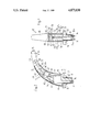
- FIG. 1 illustrates in front view, partially in section, a water dispenser containing a plumbing fixture and constructed according to the present invention
- FIG. 2 illustrates in side view, also partly in section, the water dispenser depicted in FIG. 1.
- FIGS. 1 and 2 there will be recognized a water dispenser or water mixing device 12 comprising an electrically controlled fixture 10a, typically what is sometimes referred to in this art as a plumbing fixture, containing a fixture body or body member 10 at which there is formed or provided an attachment flange or flange member 14 possessing threads or threading 16.
- an electrically controlled fixture 10a typically what is sometimes referred to in this art as a plumbing fixture, containing a fixture body or body member 10 at which there is formed or provided an attachment flange or flange member 14 possessing threads or threading 16.
- This attachment flange 14 piercingly extends through a throughpass or open-ended hole or opening 18 provided in a plate or plate member 20, for instance constituted by part of a sink or washing basin.
- a nut member 22 or equivalent fixation element serves to threadably secure the threaded attachment flange member 14 at the plate or plate member 20.
- a washer or underlay disc 24 or the like, is disposed between the plate member and the nut member 22.
- the fixture body 10 has a hollow shape or construction defining therein a space or internal region, generally indicated by reference character 10b, above the location of the attachment flange member 14 and is covered by a substantially U-shaped cover or hood member 26.
- a suitable adjusting or control element for instance a threaded screw 28 it is possible to appropriately conventionally preselect the temperature of the mixed or comingled hot and cold water which flows out of the water dispenser or fixing device 12.
- each of the fixture body 10 there are arranged two heat exchangers 30 and 32 each of which are in flow communication or flow connected with a fixture connection conduit or line 34 and 36, respectively, which piercingly extend through the attachment or connection flange 14 as particularly well seen by referring to FIG. 1.
- these fixture connection conduits or lines 34 and 36 are connected in any suitable but generally known fashion with a hot water and a cold water supply conduit or line system.
- the heat exchanger 30 has hot water, generally indicated by reference character 30a, flowing therethrough and the other heat exchanger 32 has cold water, generally indicated by reference character 32a, flowing therethrough.
- Each of the heat exchangers 30 and 32 comprises a substantially block-shaped, such as a parallelepiped-shaped hollow body 30b and 32b, respectively.
- the larger side surfaces 56 and 58 of the heat exchangers 30 and 32, respectively, are arranged in somewhat spaced and parallel confronting relationship with respect to one another.
- Each heat exchanger 30 and 32 is connected by means of a conduit or pipe section 38 and 40 with a respective inlet 42 and 44 of an electrically actuatable or electrically operated valve or valve member 46 and 48, respectively.
- These valves or valve members 46 and 48 are in flow connection at the outlet sides thereof by means of further conduit or pipe sections 50 and 52, respectively, with a nozzle or jet body 54 or equivalent structure through which flows the admixed hot and cold water.
- a Peltier arrangement 60 is arranged between the neighboring side surfaces 56 and 58 of the heat exchangers 30 and 32, respectively.
- the mutually confronting or oppositely situated large outer surfaces or regions 60a and 60b of the Peltier arrangement 60 contact the side surfaces 56 and 58 of the heat exchangers 30 and 32, respectively.
- the Peltier arrangement 60 comprises a plurality of Peltier elements, also referred to as thermocouples, which are electrically connected in series to form a thermopile and are thermally coupled in parallel.
- the hot side of the Peltier arrangement 60 is in good thermal coupling or contact with the side surface 56 of the heat exchanger 30 and the cold side thereof is in good thermal coupling or contact with the side surface 58 of the other heat exchanger 32.
- the connection lines or conductors 62 of the Peltier arrangement 60 are electrically connected by means of terminals 64 or equivalent structure with further connection lines or conductors 66 which lead to a suitable and therefore here only schematically depicted electronic control or control device 68.
- This electronic control device 68 is electrically connected by further not here particularly shown control lines with both of the valves or valve members 46 and 48 and with a suitable proximity sensor 70, for instance an ultrasonic or infrared sensor, arranged at the head end 12a of the water dispenser or mixing device 12.
- the hands of a user are located at the region of the proximity sensor 70 such furnishes an electrical signal to the electronic control or control device 68.
- This electronic control device 68 evaluates the signal, amplifies the same and delivers an opening command to the valves 46 and 48, with the result that the hot water 30a and the cold water 32a each flow in the direction of the arrow A shown at the bottom of FIG. 2 through the associated heat exchanger 30 and 32, the conduit or line sections 38 and 40, the valves 46 and 48 and the further conduit or line sections 50 and 52 to the nozzle or jet body 54.
- the hot water 30a and cold water 32a are admixed and the admixed or commingled water then departs at that location from the water dispenser or mixing device 12 and flows into contact with the hands of the user which are to be washed.
- the heat exchanger 30 through which flows the hot water 30a heats up very rapidly and the other heat exchanger 32, through which flows the cold water 32a, accommodates its temperature to that of the cold water. Consequently, the Peltier arrangement 60 is exposed to a relatively large temperature difference or differential. This temperature difference produces an electric potential or voltage which is applied by means of the connection conductors or lines 62 and 66 at the electronic control or control device 68.
- the storage element 68a thereof here the accumulator or capacitor, is charged and by virtue of such energy the valves 46 and 48 can be appropriately opened and also there are powered the entire electronic components within the electronic control 68.
- the proximity sensor 70 delivers an appropriate signal to the electronic control or control device 68 by means of which there are controlled further commands serving for closing of the previously opened valves 46 and 48.
- the heat exchanger 30 through which flows the hot water 30a is structured to have an increased mass or storage mass which thus increases its heat storage capacity. In this way, the temperature difference between both of the heat exchangers 30 and 32 lasts over a longer time span.
- fittings which can be constructed in accordance with the teachings and principles of the present invention, are, for instance, fittings having electrical or electronic displays as well as optical or acoustical warning devices in respect of the temperature, the pressure, the throughflow quantity and so forth of the fluent or flowable medium.
Landscapes
- Engineering & Computer Science (AREA)
- General Engineering & Computer Science (AREA)
- Mechanical Engineering (AREA)
- Domestic Plumbing Installations (AREA)
- Magnetically Actuated Valves (AREA)
- Devices For Dispensing Beverages (AREA)
- Switches With Compound Operations (AREA)
- Threshing Machine Elements (AREA)
- Lining Or Joining Of Plastics Or The Like (AREA)
- Bidet-Like Cleaning Device And Other Flush Toilet Accessories (AREA)
- Control Of Temperature (AREA)
Applications Claiming Priority (2)
| Application Number | Priority Date | Filing Date | Title |
|---|---|---|---|
| CH365887 | 1987-09-22 | ||
| CH03658/87 | 1987-09-22 |
Publications (1)
| Publication Number | Publication Date |
|---|---|
| US4873830A true US4873830A (en) | 1989-10-17 |
Family
ID=4260741
Family Applications (1)
| Application Number | Title | Priority Date | Filing Date |
|---|---|---|---|
| US07/245,287 Expired - Lifetime US4873830A (en) | 1987-09-22 | 1988-09-16 | Electrically controlled plumbing fixture of a hot and cold water dispenser |
Country Status (6)
| Country | Link |
|---|---|
| US (1) | US4873830A (de) |
| EP (1) | EP0312737B1 (de) |
| JP (1) | JP2724473B2 (de) |
| AT (1) | ATE77457T1 (de) |
| CA (1) | CA1304336C (de) |
| DE (1) | DE3872156D1 (de) |
Cited By (15)
| Publication number | Priority date | Publication date | Assignee | Title |
|---|---|---|---|---|
| USD325771S (en) | 1989-01-27 | 1992-04-28 | Les Robinets Presto | Electronically controlled faucet |
| US20060180221A1 (en) * | 2005-02-14 | 2006-08-17 | Chung Cheng Faucet Co., Ltd. | Water outlet tubing structure for faucets |
| ES2302611A1 (es) * | 2006-04-03 | 2008-07-16 | Griferias Grober, S.L. | Sistema de recarga de bateria para griferia. |
| US7448553B2 (en) | 2005-04-19 | 2008-11-11 | Masco Corporation Of Indiana | Fluid mixer |
| US7458520B2 (en) | 2005-04-19 | 2008-12-02 | Masco Corporation Of Indiana | Electronic proportioning valve |
| US7475827B2 (en) | 2005-04-19 | 2009-01-13 | Masco Corporation Of Indiana | Fluid mixer |
| US20090216452A1 (en) * | 2005-07-05 | 2009-08-27 | Develop Tech Resources | Energy recovery within a fluid distribution network using geographic information |
| US7584898B2 (en) | 2005-07-01 | 2009-09-08 | Masco Corporation Of Indiana | Manual override for electronic proportioning valve |
| US20130207390A1 (en) * | 2009-05-26 | 2013-08-15 | Leviathan Energy Hydroelectric Ltd. | Hydroelectric in-pipe turbine uses |
| US20130340846A1 (en) * | 2012-06-22 | 2013-12-26 | Kevin T. Peel | Plumbing fixture with heating elements |
| US9733654B2 (en) | 2009-08-04 | 2017-08-15 | William A. Cline | Dual functional temperature control system applicator system |
| WO2018218372A1 (en) * | 2017-06-01 | 2018-12-06 | M.I.S. Electronics Inc. | Fluid dispensing system |
| GB2602346A (en) * | 2020-12-23 | 2022-06-29 | James Wyllie Nicholas | Combined thermal heater cooler sensor tap and valve |
| US11391021B2 (en) | 2017-11-09 | 2022-07-19 | Kohler Mira Limited | Plumbing component |
| DE102022104572A1 (de) | 2022-02-25 | 2023-08-31 | Grohe Ag | Brause für eine Sanitärarmatur |
Families Citing this family (4)
| Publication number | Priority date | Publication date | Assignee | Title |
|---|---|---|---|---|
| JP2002320394A (ja) * | 2001-04-19 | 2002-10-31 | Inax Corp | ダブル配管間発電装置 |
| NL1035475C2 (nl) * | 2008-05-27 | 2009-11-30 | Jurgen Verwoert | Sanitaire tapkraan met generator voor elektrische energie. |
| DE102013100078A1 (de) | 2012-02-24 | 2013-08-29 | WIMTEC Elektronische Steuerungs- und Meßgeräte GmbH | Sanitäre Armatur |
| DE102013017176A1 (de) * | 2013-10-16 | 2015-04-16 | Grohe Ag | Sanitärarmatur mit Peltierelement |
Citations (10)
| Publication number | Priority date | Publication date | Assignee | Title |
|---|---|---|---|---|
| US3083543A (en) * | 1961-03-28 | 1963-04-02 | Varo | Devices and systems for cooling or heating fluids |
| US3225549A (en) * | 1962-04-18 | 1965-12-28 | Thore M Elfving | Thermoelectric cooling device |
| US3502080A (en) * | 1965-06-28 | 1970-03-24 | Max L Hirschhorn | Thermoelectrically cooled surgical instrument |
| US3618590A (en) * | 1969-06-27 | 1971-11-09 | Hoffmann La Roche | Thermal electric dental pulp tester |
| US4308013A (en) * | 1980-06-19 | 1981-12-29 | Emery Major | Thermoelectric diagnostic instrument |
| WO1985001337A1 (en) * | 1983-09-23 | 1985-03-28 | Parsons Natan E | Ultrasonic flow-control system |
| US4520305A (en) * | 1983-08-17 | 1985-05-28 | Cauchy Charles J | Thermoelectric generating system |
| EP0158930A2 (de) * | 1984-04-17 | 1985-10-23 | Hans Grohe GmbH & Co KG | Vorrichtung zur Steuerung des Durchflusses einer Flüssigkeit |
| EP0193702A2 (de) * | 1985-03-04 | 1986-09-10 | Ideal-Standard Gmbh | Wassermischarmatur, insbesondere Einhebelmischarmatur |
| US4735357A (en) * | 1986-03-07 | 1988-04-05 | Stephen O. Gregory | Modular water facuet with automatic water supply system |
-
1988
- 1988-08-25 AT AT88113822T patent/ATE77457T1/de not_active IP Right Cessation
- 1988-08-25 EP EP88113822A patent/EP0312737B1/de not_active Expired - Lifetime
- 1988-08-25 DE DE8888113822T patent/DE3872156D1/de not_active Expired - Lifetime
- 1988-09-16 US US07/245,287 patent/US4873830A/en not_active Expired - Lifetime
- 1988-09-21 CA CA000577972A patent/CA1304336C/en not_active Expired - Lifetime
- 1988-09-21 JP JP63237493A patent/JP2724473B2/ja not_active Expired - Fee Related
Patent Citations (12)
| Publication number | Priority date | Publication date | Assignee | Title |
|---|---|---|---|---|
| US3083543A (en) * | 1961-03-28 | 1963-04-02 | Varo | Devices and systems for cooling or heating fluids |
| US3225549A (en) * | 1962-04-18 | 1965-12-28 | Thore M Elfving | Thermoelectric cooling device |
| US3502080A (en) * | 1965-06-28 | 1970-03-24 | Max L Hirschhorn | Thermoelectrically cooled surgical instrument |
| US3618590A (en) * | 1969-06-27 | 1971-11-09 | Hoffmann La Roche | Thermal electric dental pulp tester |
| US4308013A (en) * | 1980-06-19 | 1981-12-29 | Emery Major | Thermoelectric diagnostic instrument |
| US4520305A (en) * | 1983-08-17 | 1985-05-28 | Cauchy Charles J | Thermoelectric generating system |
| WO1985001337A1 (en) * | 1983-09-23 | 1985-03-28 | Parsons Natan E | Ultrasonic flow-control system |
| US4520516A (en) * | 1983-09-23 | 1985-06-04 | Parsons Natan E | Ultrasonic flow-control system |
| EP0158930A2 (de) * | 1984-04-17 | 1985-10-23 | Hans Grohe GmbH & Co KG | Vorrichtung zur Steuerung des Durchflusses einer Flüssigkeit |
| US4618091A (en) * | 1984-04-17 | 1986-10-21 | Hans Grohe Gmbh & Co. Kg | Apparatus for controlling the passage of a liquid |
| EP0193702A2 (de) * | 1985-03-04 | 1986-09-10 | Ideal-Standard Gmbh | Wassermischarmatur, insbesondere Einhebelmischarmatur |
| US4735357A (en) * | 1986-03-07 | 1988-04-05 | Stephen O. Gregory | Modular water facuet with automatic water supply system |
Cited By (55)
| Publication number | Priority date | Publication date | Assignee | Title |
|---|---|---|---|---|
| USD325771S (en) | 1989-01-27 | 1992-04-28 | Les Robinets Presto | Electronically controlled faucet |
| US20060180221A1 (en) * | 2005-02-14 | 2006-08-17 | Chung Cheng Faucet Co., Ltd. | Water outlet tubing structure for faucets |
| US7448553B2 (en) | 2005-04-19 | 2008-11-11 | Masco Corporation Of Indiana | Fluid mixer |
| US7458520B2 (en) | 2005-04-19 | 2008-12-02 | Masco Corporation Of Indiana | Electronic proportioning valve |
| US7475827B2 (en) | 2005-04-19 | 2009-01-13 | Masco Corporation Of Indiana | Fluid mixer |
| US7584898B2 (en) | 2005-07-01 | 2009-09-08 | Masco Corporation Of Indiana | Manual override for electronic proportioning valve |
| US20090216452A1 (en) * | 2005-07-05 | 2009-08-27 | Develop Tech Resources | Energy recovery within a fluid distribution network using geographic information |
| ES2302611A1 (es) * | 2006-04-03 | 2008-07-16 | Griferias Grober, S.L. | Sistema de recarga de bateria para griferia. |
| ES2302611B1 (es) * | 2006-04-03 | 2009-05-20 | Griferias Grober, S.L. | Sistema de recarga de bateria para griferia. |
| US20130207390A1 (en) * | 2009-05-26 | 2013-08-15 | Leviathan Energy Hydroelectric Ltd. | Hydroelectric in-pipe turbine uses |
| US9523344B2 (en) * | 2009-05-26 | 2016-12-20 | Leviathan Energy Hydroelectric Ltd. | Hydroelectric in-pipe turbine uses |
| US9733654B2 (en) | 2009-08-04 | 2017-08-15 | William A. Cline | Dual functional temperature control system applicator system |
| US9594383B2 (en) | 2012-06-22 | 2017-03-14 | Kohler Mira Limited | Shower head with integrated mixing valve |
| US9909288B2 (en) | 2012-06-22 | 2018-03-06 | Kohler Mira Limited | Plumbing fixture with mixing valve and controller |
| US20130340831A1 (en) * | 2012-06-22 | 2013-12-26 | Kevin T. Peel | System and method for remotely disinfecting plumbing fixtures |
| CN103511725A (zh) * | 2012-06-22 | 2014-01-15 | 柯勒米拉有限公司 | 带有用户界面的管道附件 |
| US9260843B2 (en) | 2012-06-22 | 2016-02-16 | Kohler Mira Limited | Valve disinfecting method |
| US9260844B2 (en) | 2012-06-22 | 2016-02-16 | Kohler Mira Limited | Shower head with integrated mixing valve |
| US9260842B2 (en) * | 2012-06-22 | 2016-02-16 | Kohler Mira Limited | Valve with heating element |
| US9273450B2 (en) * | 2012-06-22 | 2016-03-01 | Kohler Mira Limited | Plumbing fixture with heating elements |
| US9340959B2 (en) | 2012-06-22 | 2016-05-17 | Kohler Mira Limited | Plumbing fixture with mixing valve and controller |
| US9340958B2 (en) | 2012-06-22 | 2016-05-17 | Kohler Mira Limited | Mixing valve |
| US9366015B2 (en) | 2012-06-22 | 2016-06-14 | Kohler Mira Limited | Method of controlling mixing valve |
| US9376792B2 (en) | 2012-06-22 | 2016-06-28 | Kohler Mira Limited | Plumbing fixture with integrated mixing valve |
| US9476188B2 (en) * | 2012-06-22 | 2016-10-25 | Kohler Mira Limited | System and method for remotely disinfecting plumbing fixtures |
| US9506227B2 (en) | 2012-06-22 | 2016-11-29 | Kohler Mira Limited | Plumbing fixture with user interface |
| US20130340846A1 (en) * | 2012-06-22 | 2013-12-26 | Kevin T. Peel | Plumbing fixture with heating elements |
| US9650769B2 (en) | 2012-06-22 | 2017-05-16 | Kohler Mira Limited | Mixing valve |
| US9650770B2 (en) | 2012-06-22 | 2017-05-16 | Kohler Mira Limited | Mixing valve |
| US9683352B2 (en) | 2012-06-22 | 2017-06-20 | Kohler Mira Limited | Valve disinfecting method |
| US9689149B2 (en) | 2012-06-22 | 2017-06-27 | Kohler Mira Limited | Flow control valve |
| US9758950B2 (en) | 2012-06-22 | 2017-09-12 | Kohler Mira Limited | Plumbing fixture with integrated mixing valve |
| US9822513B2 (en) | 2012-06-22 | 2017-11-21 | Kohler Mira Limited | Mixing valve |
| US20130340847A1 (en) * | 2012-06-22 | 2013-12-26 | Kevin T. Peel | Valve with heating element |
| US9920507B2 (en) | 2012-06-22 | 2018-03-20 | Kohler Mira Limited | Mixing valve |
| US9957700B2 (en) | 2012-06-22 | 2018-05-01 | Kohler Mira Limited | Valve with heating element |
| US9957699B2 (en) | 2012-06-22 | 2018-05-01 | Kohler Mira Limited | Plumbing fixture with heating elements |
| US10000914B2 (en) | 2012-06-22 | 2018-06-19 | Kohler Mira Limited | Plumbing fixture with user interface |
| US10041234B2 (en) | 2012-06-22 | 2018-08-07 | Kohler Mira Limited | Mixing valve |
| US10087607B2 (en) | 2012-06-22 | 2018-10-02 | Kohler Mira Limited | Shower head with integrated mixing valve |
| US10106964B2 (en) | 2012-06-22 | 2018-10-23 | Kohler Mira Limited | Method of controlling mixing valve |
| US11674293B2 (en) | 2012-06-22 | 2023-06-13 | Kohler Mira Limited | Mixing valve |
| US10494798B2 (en) | 2012-06-22 | 2019-12-03 | Kohler Mira Limited | Plumbing fixture with heating element |
| US10501915B2 (en) | 2012-06-22 | 2019-12-10 | Kohler Mira Limited | Plumbing fixture with user interface |
| US10577784B2 (en) | 2012-06-22 | 2020-03-03 | Kohler Mira Limited | Shower head with integrated mixing valve |
| US10604919B2 (en) | 2012-06-22 | 2020-03-31 | Kohler Mira Limited | Plumbing fixture with heating element |
| US11230829B2 (en) | 2012-06-22 | 2022-01-25 | Kohler Mira Limited | Mixing valve |
| EP3631969A4 (de) * | 2017-06-01 | 2021-03-03 | M.I.S. Electronics Inc. | Flüssigkeitsausgabesystem |
| US11346089B2 (en) | 2017-06-01 | 2022-05-31 | M.I.S. Electronics Inc. | Fluid dispensing system |
| WO2018218372A1 (en) * | 2017-06-01 | 2018-12-06 | M.I.S. Electronics Inc. | Fluid dispensing system |
| US11391021B2 (en) | 2017-11-09 | 2022-07-19 | Kohler Mira Limited | Plumbing component |
| US12392119B2 (en) | 2017-11-09 | 2025-08-19 | Kohler Mira Limited | Plumbing component |
| GB2602346A (en) * | 2020-12-23 | 2022-06-29 | James Wyllie Nicholas | Combined thermal heater cooler sensor tap and valve |
| GB2602346B (en) * | 2020-12-23 | 2025-03-12 | James Wyllie Nicholas | Combined thermal heater cooler sensor tap and valve |
| DE102022104572A1 (de) | 2022-02-25 | 2023-08-31 | Grohe Ag | Brause für eine Sanitärarmatur |
Also Published As
| Publication number | Publication date |
|---|---|
| JP2724473B2 (ja) | 1998-03-09 |
| EP0312737B1 (de) | 1992-06-17 |
| JPH01102133A (ja) | 1989-04-19 |
| EP0312737A1 (de) | 1989-04-26 |
| DE3872156D1 (de) | 1992-07-23 |
| CA1304336C (en) | 1992-06-30 |
| ATE77457T1 (de) | 1992-07-15 |
Similar Documents
| Publication | Publication Date | Title |
|---|---|---|
| US4873830A (en) | Electrically controlled plumbing fixture of a hot and cold water dispenser | |
| US4358652A (en) | Fluid heater apparatus | |
| US4384568A (en) | Solar heating system | |
| US4618091A (en) | Apparatus for controlling the passage of a liquid | |
| US4980933A (en) | Washing device for parts of human body | |
| US5586572A (en) | Hydrothermal stabilizer | |
| US7151892B2 (en) | Rapid electric heating water dispenser | |
| CN207299499U (zh) | 一种组合式智能恒温电热水器 | |
| CN105393063A (zh) | 流体温度调节设备 | |
| CN112344565A (zh) | 水路控制系统和相变热水器 | |
| US20070108304A1 (en) | Hot water supply device | |
| CN216113972U (zh) | 蒸汽锅炉及具有其的蒸汽拖把 | |
| US2476927A (en) | Electrical water heater | |
| US12523379B2 (en) | Water heating system | |
| US5727117A (en) | Device for saving water and energy in electric water heaters | |
| JPH0585815B2 (de) | ||
| IE55348B1 (en) | A heater for use with an apparatus for supplying instantaneous hot water for washing purposes | |
| JP2529203B2 (ja) | 給湯システム | |
| JPH0230652Y2 (de) | ||
| JPH0119010Y2 (de) | ||
| CN223090840U (zh) | 一种即热式热水器的压差连通结构 | |
| JP3564871B2 (ja) | ロータンクの手洗い用電気温水器 | |
| JPH0894177A (ja) | 電気温水器 | |
| WO2021205423A1 (en) | Instant water heater unit | |
| ES2130561T3 (es) | Calentador de agua. |
Legal Events
| Date | Code | Title | Description |
|---|---|---|---|
| AS | Assignment |
Owner name: KWC AG, HAUPTSTRASSE 3, 5726 UNTERKULM, SWITZERLAN Free format text: ASSIGNMENT OF ASSIGNORS INTEREST.;ASSIGNOR:BLATTLER, ERNST;REEL/FRAME:004956/0562 Effective date: 19880902 Owner name: KWC AG, A CORP. OF SWITZERLAND,SWITZERLAND Free format text: ASSIGNMENT OF ASSIGNORS INTEREST;ASSIGNOR:BLATTLER, ERNST;REEL/FRAME:004956/0562 Effective date: 19880902 |
|
| STCF | Information on status: patent grant |
Free format text: PATENTED CASE |
|
| FEPP | Fee payment procedure |
Free format text: PAYOR NUMBER ASSIGNED (ORIGINAL EVENT CODE: ASPN); ENTITY STATUS OF PATENT OWNER: LARGE ENTITY |
|
| FPAY | Fee payment |
Year of fee payment: 4 |
|
| FPAY | Fee payment |
Year of fee payment: 8 |
|
| FPAY | Fee payment |
Year of fee payment: 12 |