US4875484A - Method for generating a low frequency electric stimulus signal and low frequency electric stimulus signal generating apparatus - Google Patents
Method for generating a low frequency electric stimulus signal and low frequency electric stimulus signal generating apparatus Download PDFInfo
- Publication number
- US4875484A US4875484A US07/103,010 US10301087A US4875484A US 4875484 A US4875484 A US 4875484A US 10301087 A US10301087 A US 10301087A US 4875484 A US4875484 A US 4875484A
- Authority
- US
- United States
- Prior art keywords
- voltage
- current
- stimulus signal
- stimulus
- signal
- Prior art date
- Legal status (The legal status is an assumption and is not a legal conclusion. Google has not performed a legal analysis and makes no representation as to the accuracy of the status listed.)
- Expired - Fee Related
Links
Images


Classifications
-
- A—HUMAN NECESSITIES
- A61—MEDICAL OR VETERINARY SCIENCE; HYGIENE
- A61N—ELECTROTHERAPY; MAGNETOTHERAPY; RADIATION THERAPY; ULTRASOUND THERAPY
- A61N1/00—Electrotherapy; Circuits therefor
- A61N1/02—Details
- A61N1/04—Electrodes
-
- A—HUMAN NECESSITIES
- A61—MEDICAL OR VETERINARY SCIENCE; HYGIENE
- A61N—ELECTROTHERAPY; MAGNETOTHERAPY; RADIATION THERAPY; ULTRASOUND THERAPY
- A61N1/00—Electrotherapy; Circuits therefor
- A61N1/18—Applying electric currents by contact electrodes
- A61N1/32—Applying electric currents by contact electrodes alternating or intermittent currents
- A61N1/36—Applying electric currents by contact electrodes alternating or intermittent currents for stimulation
- A61N1/36014—External stimulators, e.g. with patch electrodes
- A61N1/36021—External stimulators, e.g. with patch electrodes for treatment of pain
-
- F—MECHANICAL ENGINEERING; LIGHTING; HEATING; WEAPONS; BLASTING
- F04—POSITIVE - DISPLACEMENT MACHINES FOR LIQUIDS; PUMPS FOR LIQUIDS OR ELASTIC FLUIDS
- F04C—ROTARY-PISTON, OR OSCILLATING-PISTON, POSITIVE-DISPLACEMENT MACHINES FOR LIQUIDS; ROTARY-PISTON, OR OSCILLATING-PISTON, POSITIVE-DISPLACEMENT PUMPS
- F04C5/00—Rotary-piston machines or pumps with the working-chamber walls at least partly resiliently deformable
-
- A—HUMAN NECESSITIES
- A61—MEDICAL OR VETERINARY SCIENCE; HYGIENE
- A61N—ELECTROTHERAPY; MAGNETOTHERAPY; RADIATION THERAPY; ULTRASOUND THERAPY
- A61N1/00—Electrotherapy; Circuits therefor
- A61N1/18—Applying electric currents by contact electrodes
- A61N1/32—Applying electric currents by contact electrodes alternating or intermittent currents
- A61N1/36—Applying electric currents by contact electrodes alternating or intermittent currents for stimulation
- A61N1/36014—External stimulators, e.g. with patch electrodes
- A61N1/36025—External stimulators, e.g. with patch electrodes for treating a mental or cerebral condition
Definitions
- the present invention relates to a method of generating a low frequency electrical stimulus signal to provide an electrical stimulus to a biological body, and also to an apparatus for generating a low frequency electrical stimulus signal.
- a conventional electric stimulus signal generating technique for instance, a method of producing an electric stimulus signal, the pulse repetition frequency of which is not varied in accordance with a lapse of time, and giving such a stimulus signal to a biological body, especially to the body's sympathetic nerves and parasympathetic nerves.
- a conventional electric stimulus signal generating apparatus is known from, for example, Japanese patent publication No. 56-5543 (referred to as a "printed publication I") and Japanese utility model publication No. 56-22921 (referred to as a "printed publication II").
- the first reference describes such a technique in accordance with the 1/f fluctuation theory, i.e., the signal of music being analyzed in the frequency spectrum, and the power spectrum density of the analyzed signal being inversely proportional to the frequency, while the frequency of the electric stimulus signal is changed in a relatively long time range from 0.5 to 4 seconds within a range from 10 to 100 Hz, for producing the electric stimulus signal.
- the second reference describes a technique of recording the pulse repetition frequency of the electric stimulus signal and also the irregular pulse pattern when the generating duration time of the same pulse repetition is varied, and reproducing the recorded data from the recording medium in accordance with the 1/f fluctuation theory.
- the tempo of music is synchronized with the nerve and furthermore tissue and cells, the effects to reduce pain can be emphasized. Accordingly, this effect can be realized in that if the sound volume level (i.e., sound pressure level) is used as the sound information, the percutaneous stimulus can be provided to a biological body in synchronism with the tempo of the music.
- the sound volume level i.e., sound pressure level
- the percutaneous stimulus is provided to a biological body in accordance with the frequency of the 1/f fluctuation theory, it is practically difficult to adjust this stimulus with the tempo of the music.
- neither method can provide both stimulus to a biological body in real time. Accordingly, since the electric stimulus is given to a biological body even when the music is under rest condition (in case of rest mode and lower sound pressure), this stimulus is not matched with the experimental mental reduction of unpleasantness of a biological body. As a result, the biological body feels this stimulus as the continuous variation of mere stimulus patterns, so that there is not as much curative effect to reduce the pain.
- Primary objects of the present inventions are to provide methods and apparatus for generating a low frequency electric stimulus signal which can provide the electric stimulus signal (percutaneous stimulus) to a biological body in synchronism with the tempo of the hearing stimulus.
- Secondary objects of the present inventions are to provide methods and apparatus for generating a low frequency electric stimulus signal, wherein the hearing stimulus can be given to a biological body in synchronism with the percutaneous stimulus in substantially real time.
- either one or both of the current or the voltage is controlled in response to the sound volume level supplied from the sound source to modulate the electric stimulus signal.
- the frequency of the electric stimulus signal employed in the present invention is selected to be a low frequency.
- the sound volume level is first sampled at the rate at which a biological body feels it in substantially real time; secondly, the respective sound levels obtained by the sampling are converted into frequencies corresponding to the low frequency region; and thirdly, current or voltage frequency modulation is performed by these frequencies to control either the current or voltage.
- the low frequency range of the sound volume level-to-frequency conversion is preferably selected to be from 0 to 60 Hz.
- the sound volume level is first sampled at a predetermined rate at which a biological body feels it in substantially real time; secondly, the respective sound volume levels acquired by this sampling operation are converted into amplitude control values corresponding thereto; and finally, the amplitude modulation is carried out in accordance with these amplitude control values within a range of 0 to 100% of the initially set amplitude value of the voltage or current, so as to control the current or voltage.
- the sound volume level is sampled at a predetermined rate at which a biological body feels it at substantially real time; secondly, the respective sound levels obtained by this sampling operation are converted into the pulse number control values; and thirdly, the pulse number modulation is carried out in accordance with these pulse number control values so as to effect the current or voltage control.
- the pulse number modulation is performed in such a manner that the number of the pulse is equal to from 0 to 30 in response to the second volume level. Moreover, the above-described sampling operation is performed in a period from 0.01 to 0.5 second.
- a control section wherein a sound volume level derived from a sound source is sampled at a rate at which the biological body can feel it in substantially real time is concluded, the respective sample sound levels are converted into frequencies corresponding to low frequencies and output, and predetermined control information, and a current/voltage controlling section where current and voltage stimulus signals are frequency-modulated separately based upon the frequencies, the control section and current/voltage controlling section are included in a stimulus signal generating section.
- the stimulus generating section includes a control system selecting section for switching only one of the current and voltage stimulus signals based upon control information derived from the control section and for outputting the same as the electric stimulus signal.
- the current control section includes a waveform generating section for outputting a voltage waveform signal corresponding to the sound volume levels, and a current stimulus signal generating circuit for outputting a current stimulus signal having the same waveform as that of an input voltage waveform signal.
- control section includes a waveform generating section for generating a voltage waveform signal having a frequency corresponding to the sound volume level, and a voltage stimulus signal generating circuit for outputting the input voltage waveform signal as a voltage stimulus signal.
- the low frequency region is preferably determined by 0 to 60 Hz.
- the sampling period is preferably selected to be 0.01 to 0.5 second.
- control section includes means for subdividing the sound volume levels into a plurality of level steps, ROM for previously storing a sound volume level-to-frequency conversion table, and means for reading out from the ROM a frequency corresponding to the sound volume level at each sampling operation.
- the sound volume level is set to a zero level of the sound volume level when the sound volume level is equal to a zero level, or a lower level.
- the frequency of the electric stimulus signal is selected to be at a low frequency, for instance, 0 to 60 Hz, so that the mental physical attributes of a biological body can be relaxed--by a pulling phenomenon against the natural vibration of automatic nerve (for instance, in the phenomena of "KEDACHI (goose flesh)” and “FURUE (tremble)"--to present cool feeling for the biological body, the natural vibration being approximately 15 Hz.
- the method of generating a low frequency electric stimulus signal of a third embodiment in response to a waveform of sound information derived from a sound source, at least one of the controls of the current and voltage is performed to modulate the electric stimulus signal at a rhythm.
- the frequency of the electric stimulus signal is selected to be at a low frequency.
- the stimulus signal generating section including: a waveform control section for outputting a rhythmic-modulated waveform signal by deriving low frequency sound information from a sound source, a current control section for generating a current controlled stimulus signal based upon the rhythmic-modulated waveform signal, a voltage control section for generating a voltage controlled stimulus signal based upon the rhythmic modulated waveform signal, a control system selecting section for outputting at least one of the current stimulus signal or the voltage stimulus signal as the electric stimulus signal, and a control section for controlling operations of the control sections and selection based upon a signal derived from the input section.
- the current control section includes an intensity setting circuit of the rhythmic-modulation waveform signal, and a current stimulus signal generating circuit for outputting a current stimulus signal having the same waveform as that of a waveform input from the intensity setting circuit, and further the voltage control section includes a voltage stimulus circuit for outputting a voltage stimulus signal by adjusting the rhythmic-modulated waveform signal.
- either the control of the current, or the voltage is performed based upon the waveform of the sound information so as to irregular modulate the electric stimulus signal.
- a biological body can be electrically stimulated, i.e., being provided percutaneous stimulus in accordance with the tempo of the music etc.
- the biological body can be stimulated by the waveforms of the quasi-sound information which has been generated in the quasi-sound production. Consequently, since the biological body can be stimulated with the percutaneous stimulus at the rate at which he can feel it in substantially real time, the pain reduction and curative effects can be more improved, as compared with the conventional musical medical treatment.
- the unpleasant feelings can be effectively eliminated.
- the low frequency electric stimulus signal generating apparatus of the fifth embodiment which comprises a stimulus signal generating section which includes a control section in which sound volume levels supplied from a sound source are sampled at a rate at which a biological body feels it in substantially real time, each of the sampled volume levels is converted into a corresponding amplitude control value and the resultant value is output, and predetermined control information is output, and a current/voltage control section for performing an amplitude modulation in response to the amplitude control value within a range of 0 to 100% of an initial set amplitude value of current and voltage stimulus signals.
- the stimulus signal generating section includes a control system selecting section for switching only one of the current and voltage stimulus signals based upon control information derived from the control section and for outputting the same as the electric stimulus signal.
- the current control section includes a waveform generating section for outputting a voltage waveform having an arbitrary frequency, an intensity setting circuit for controlling an intensity of the voltage waveform signal by the amplitude control value, and a current stimulus signal generating circuit for outputting a current stimulus signal having the same waveform as that of the voltage waveform signal input from the intensity setting circuit.
- the voltage control section includes a waveform generating section for outputting a voltage waveform signal having an arbitrary frequency, and a voltage stimulus signal generating circuit for controlling an intensity of the input voltage waveform signal based upon the amplitude control value and for outputting the same as a voltage stimulus signal.
- the frequency is selected from 0 to 60 Hz.
- the sampling operation is performed within a time period from 0.01 to 0.5 seconds.
- control section includes means for subdividing the sound volume levels into a plurality of level steps, and means for converting the subdivided levels into the corresponding amplitude control values and for outputting the converted control values.
- the electric stimulus signal having 24 steps is obtained as the amplitude control value within a range from 0 to 100% of the initial setting intensity.
- the control information previously stored in the control section is read out and the alternating stimulus of the current and voltage is applied to a biological body without utilizing the sound information derived from the sound source.
- the above sound information derived from the sound source is only used for the hearing stimulus.
- the time interval between the succeeding alternating operations is preferably settable at random within a range from several seconds to several tens of seconds.
- the alternating time interval is preferably selected to be approximately 2 seconds to 1 minute.
- the stimulus signal generating section includes: a control section for previously storing control information which is readily accessible; a current control section for generating a current stimulus signal controlled by the control information, a voltage control section for generating a voltage stimulus signal controlled by the control information, and a control system selecting section for alternately switching the current stimulus signal and the current stimulus signal and the voltage stimulus signal based upon the control signal so as to output the same as the electric stimulus signal.
- control information of the current and electric stimulus signals is selected from more than one sort of waveforms, frequencies and intensity, and the control information is selectable and variable based upon external input.
- the alternating selection of the current and voltage stimulus signal is performed at random.
- a time interval of the alternating selection of the current and voltage stimulus signals is set at random within several seconds to several tens of seconds.
- a frequency of the electric stimulus signal is selected from a low frequency of 0 to 60 Hz.
- the control of the current or voltage is performed based upon the waveforms of the sound information so as to irregularly the electric stimulus signal. Accordingly, the frequency, waveform, and intensity of the sound information of the favorable music are previously stored, so that a biological body can the electric stimulus (percutaneous stimulus) in response to the tempo of this favorable music. As a result, the percutaneous stimulus can be applied to a biological body at predetermined timing at which he can feel this stimulus in substantially real time, with the result that higher curative effects than in the conventional musical curative method can be expected according to the present invention.
- the current control system and the voltage control system are alternately switched to give the alternating stimulus to a biological body, with the result that it is possible to avoid not having a biological body feel no stimulus upon receipt of the electric stimulus, and therefore the unpleasant feeling can be eliminated, the pain effects can be reduced, and the curing effects can be improved.
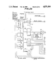
- FIG. 1 is a block diagram illustrating a basic arrangement to explain the present invention
- FIGS. 2A and 2B are block diagrams, each of which shows a portion of detailed block diagram of a low frequency electric stimulus signal generating apparatus to explain the present invention
- FIGS. 3A to 3K are voltage waveform signal diagrams for explaining the present invention.
- FIG. 4 is a schematic diagram for explaining a table conversion
- FIG. 5 is a functional block diagram of a CPU
- FIGS. 6 to 14 are flowcharts of the operations according to the preferred embodiments of the present invention.
- FIG. 15 is a block diagram of the current stimulus signal gen. c/ct.
- FIG. 16 is a block diagram of a c/ct. for simply amplifying the input voltage.
- FIG. 1 is a block diagram illustrating a basic arrangement to explain the present invention.
- FIGS. 2A and 2B are block diagrams each of which illustrates a portion of a detailed block diagram of a low frequency electric stimulus signal generating apparatus to explain the present invention.
- portions shown by the same reference marks a, b, c, d, e, f, g, h, i, and j should be connected to each other.
- a low frequency electric stimulus signal generating apparatus that basically includes a stimulus signal generating section 10 for generating the low frequency electric stimulus signal, a host section 12 for selectively supplying data which are required to drive the stimulus signal generating section 10, and an electrode section 14 for applying the electric stimulus signal generated to biological bodies or living body.
- the host section 12 mainly includes an input section 20 for inputting various types of signals to the stimulus signal generating apparatus 10. These signals are to set the initial conditions, predetermined conditions, to adjust the proper conditions, or to initialize the generation of the electric stimulus signal.
- the above-described predetermined conditions include, for instance, amplitudes (intensity), waveforms, frequencies, stimulus patterns, controlling systems for controlling current or voltage, and selection of electrodes.
- this host section 12 further includes a sound source device for generating music and so on, an electric converting devices, such as a speaker or earphone for reproducing the acoustic information originated from the sound source device, or a display section 21 for visually displaying the generated electric stimulus signals.
- these sound source devices instead of providing these sound source devices to the host sections 12, they may be connected, as an outer source device, to the stimulus signal generating section 10, as indicated by reference numeral 16.
- the stimulus signal generating section 10 employs the current or voltage control system.
- the volume of sound level supplied from the sound source device 16 is detected, and the physical quantities of the current, or voltage stimulus signals such as frequencies, amplitudes (intensity) or pulse are controlled in response to the detected volume levels, while these electric stimulus signals are continuously modulated, thus modulated electric stimulus signals are output from the stimulus signal generating section 10.
- the electric stimulus signals are preferably selected in such a manner that the frequency of the stimulus signals is a low frequency within the present frequency range of approximately 0 to 50 Hz, at which biological bodies such as patients who use this low frequency electric stimulus signal generating apparatus, feel pleasant.
- the stimulus signal generating section 10 mainly includes a control section 30 having a CPU (central control unit) for converting the volume level for controlling the physical quantities into predetermined controlling quantities, and for controlling other desired controls; a current control section 40 for controlling the current in response to the above-defined controlling quantities; a voltage control section 50 for controlling the voltage in response to the above-defined controlling quantities; a controlling system selecting section 60 for selecting either the voltage stimulus signal generated from the voltage control section 50, or the current stimulus signal produced from the current control section 40; and an output section 70.
- a control section 30 having a CPU (central control unit) for converting the volume level for controlling the physical quantities into predetermined controlling quantities, and for controlling other desired controls
- a current control section 40 for controlling the current in response to the above-defined controlling quantities
- a voltage control section 50 for controlling the voltage in response to the above-defined controlling quantities
- a controlling system selecting section 60 for selecting either the voltage stimulus signal generated from the voltage control section 50, or the current stimulus signal produced from the current control section 40
- an output section 70 for selecting
- this stimulus signal generating section 10 includes a waveform control section 80 for performing rhythmic stimulus (also referred to as "rhythmic modulation") by controlling the rhythm of the electric stimulus signal in such a manner that the waveforms of both the current and voltage are controlled by the sound waveform having less than approximately 200 Hz during presence of the sound, and by the quasi-sound waveform produced during absence of the sound independent of the volume level.
- rhythmic stimulus also referred to as "rhythmic modulation”
- FIGS. 2A and 2B a description will be made of the arrangements and also the controlling system. It should be noted that the same reference numerals will be employed for the same circuit arrangements as those shown in FIG. 1. In addition, since the below mentioned arrangements and controlling system are merely example, the present invention is not obviously limited to those.
- the output of the amplifier 90 is, on the other hand, transferred to an electric-acoustic converter 95 such as a speaker, or an earphone, via an electronic volume 93 which can be adjusted by an external switch SW, and an amplifier 94. Then, this output is reproduced and provided to the biological body as hearing stimulus. It should be noted that this sound reproduction system is not necessarily employed in this electric stimulus apparatus, but may be substituted by the reproduction system of the external sound source apparatus 16.
- the output of the amplifier 94 may be displayed by the light emitting display section 23 in such a manner that variations in the acoustic information are displayed.
- this output is processed in a DC converter 22 of the display section 21 and the display section is made of an LED (a light emitting diode).
- the light emitting display section 23 may be provided within the host section 12.
- control section 30 includes:
- a CPU 32 for performing various process in response to the signal from this interface 31;
- a portion of the output derived from the output port 36 is supplied as a control signal to a pulse number generator 96, and a changing switch 97 for changing the signals from PTM 35 and the pulse number generator 96.
- controlling system selecting section 60 for selecting the electric stimulus signal produced in accordance with either the current control system, or the voltage control system, and for supplying the selected electric stimulus signal to a biological body as skin stimulus.
- This selecting operation can be performed in response to a selecting system control signal derived from the output port 36, whereby either the current control system, or the voltage control system is selected, otherwise, both control system are alternately selected.
- the electric stimulus signal obtained via this controlling system selecting section 60 is transferred to an output section of the low frequency electric stimulus signal generating apparatus.
- an output section 70 electrodes for applying skin stimulus to more than one portion of the biological body are connected. A selection of the electrodes is under the control by means of an electrode selection controlling signal derived from the output port 36.
- the electric stimulus signal is modulated by controlling the frequencies of the current and voltage, amplitude and pulse number, in relation to the sound level.
- the electric stimulus signal is rhythmic-modulated by controlling the current and voltage while using properly sound waveforms and quasi-sound waveforms having a frequency lower than about 200 Hz, without utilizing the sound level.
- the electric stimulus signal is stimulus pattern-modulated by controlling the current and voltage patterns based upon the combination of various control information (waveforms, frequencies and amplitudes) which is previously set in the control section, without using the sound information.
- FIG. 4 is a schematic diagram for explaining a table conversion.
- FIG. 5 is a functional block diagram of CPU 32.
- FIGS. 6 to 14 are flowcharts of the operations according to the preferred embodiment, where the respective processing steps are indicated by "S".
- a power switch is turned on to energize the music source device 16.
- acoustic information such as music is produced, thereby providing hearing stimulation to a biological body such as a patient.
- the acoustic, or sound information originated from the music sound device 16 is converted into a sound level composed of a data of a suitable number of bits, such as, for example, an 8-bit data or 256-bit data, as illustrated in the upper column of FIG. 4, by utilizing a sound volume-to-DC level converter 91 and an A/D converter 92 in real time processing.
- predetermined initial information containing the modulation, waveform, frequency, electrode selection, controlling system and so on is input to the control section 30 of the stimulus signal generating section 10.
- the processing is performed by the setting means of CPU 32 (S1), and corresponding control information is read out from ROM 34, or converted into predetermined control information. Thereafter, the above-described control information is supplied to the respective circuit arrangement components of the output port 36 to set the initial conditions (S2).
- a waveform select signal is transferred to a waveform generating section 41 to actuate the waveform generating circuit 45, while this control signal is sent to the pulse width data section 44 so as to initial-set the proper pulse width.
- the frequency of the voltage waveform signal from the waveform generating circuit 45 is initially in such a manner that a biological body feels the maximum stimulation, for instance, 30 Hz, when the waveform of the electric stimulus signal is the same.
- This initial setting of the frequency is set independent of presence of the sound information supplied from the music sound device 16.
- control signal is supplied to the voltage controlling and current controlling system selecting section 60 in order to select either controlling system, thereby determining the corresponding electric stimulus signal.
- the intensity of these electric stimulus signals is set every time the control signal read out from ROM 34 is transferred to an intensity setting circuit 46 and a voltage stimulus generating circuit 51 in accordance to the selection by the input section 20. This intensity of the electric stimulus signal can be adjusted until a user feels pleasant while receiving this electric stimulus signal.
- the start input is transported to the control section 30 by turning on the start key of the input section 20 in the host section 12, the medical treatment commencement data is sent to the stimulus signal generating section 10 (S3) while it is processed in CPU 32, and then, the control section 30 starts to receive the volume level from the A/D converter 92(S4).
- This signal reception is carried out by the sampling operation of CPU 32.
- the respective volume levels are once written into RAM 33, which have been acquiring every sampling operation (S5), and are sequentially read out from RAM 32, if required (S6).
- the volume level of data of suitable bit numbers such, for example, as the 8-bit data or 256-bit data is converted in CPU 32 into 16-stepped level data (S7).
- the 16-step volume levels are converted into the corresponding frequencies for the lower frequency region (step 8).
- the conversion frequencies corresponding to the respective volume levels are previously stored in ROM 34 in the table form, and thus, the corresponding frequency is read out by comparing it with the frequency conversion table for every volume level (S8).
- This frequency information is sent via the output port 36 to the corresponding circuit arrangement (S9).
- the period of the sampling is preferably selected to be in a range from approximately 0.01 to 0.5 second, for example, at which a biological body feels practically in real time.
- the stimulus frequencies from 0 to 60 Hz are allocated to the 16-step volume levels, as illustrated in FIG. 4, at which a biological body feels comfort, or pleasantness.
- the frequencies of the stimulus signal are preferably selected to a range from 0 to 30 Hz.
- the volume level "0" is set to 1.5 Hz
- the level “1” is set to 2 Hz
- the level "5" corresponds to 5 Hz
- the level "10” is equal to 10 Hz
- the level "11” is selected to be 15 Hz
- -- the level 15 is selected to be 30 Hz.
- CPU 32 includes conversion means 102 for performing the frequency conversion by the sampling operation (see FIG. 5).
- this frequency is supplied to the frequency clock section 43 of the waveform generating section 41 and the voltage stimulus generating circuit 51, whereby the frequencies which have been initially set are sequentially updated by the frequencies newly converted from the received volume level. Under such condition, the current, or voltage frequency converting operation is effected, so that the frequency modulation of the electric stimulus signal can be automatically achieved.
- the sound volume level supplied from the sound source device 16 is sampled in substantially real time in synchronism with the hearing stimulus, and the frequency of the electric stimulus signal is modulated to the frequency corresponding to the sound volume level at the same time as the sampling time, according to the invention, whereby this electric stimulus signal is applied to a biological body as skin, or percutaneous stimulus.
- the most important aspect of such a frequency modulation is to substantially perform the real-time sampling, and also to set the electric stimulus (corresponding to the percutaneous stimulus) in response to this sampling operation.
- the frequency when the sound volume (sound pressure) level is equal to zero, or very low level (i.e., less than one sixteenth (1/16) of the maximum level), the frequency is set to, for instance, less than 1.5 Hz.
- the waiting time period for the succeeding stimulus is preset as follows. For instance, at the 1 Hz frequency, the waiting time period is 1 second; at the 0.5 Hz frequency, the waiting time period is 2 seconds; at the 0.25 Hz frequency, the waiting time period is set to 4 seconds.
- the control section 30 of the stimulus signal generating section 10 includes frequency forcibly converting means 103 for forcibly converting the input signal into a new frequency corresponding to the newly sampled volume level when the waiting time period becomes longer than a predetermined level, while continuously watching the converting frequency and the sound volume level.
- the setting intensity i.e., the initial setting intensity
- the volume level is converted into the frequency corresponding to the volume level which has been acquired in the succeeding sampling operation (S15).
- the resultant signal is output via the step S16.
- the present frequency is lower than 5 Hz which has been judged in the above step S13, it is compared with the sound volume level obtained at the sampling operation just before the present sampling operation (S14). If the present volume level is higher than the previous volume level, it is forcibly set to the frequency corresponding to the present volume level during the signal process in the step S15, and thereafter processed in step S16 to output the resultant signal. To the contrary, if the present volume level is lower than the comparision level, the process of the step S16 is carried out.
- the above-described overall signal process is continuously performed during the operation of the electric stimulus signal generating apparatus. It should be noted that although the converting means 102 and the frequency forcibly converting means 103 are separately employed in the preferred embodiment, the frequency forcibly converting means 103 may be assembled in the converting means 102. In addition, the operation flow is not limited to the above-described flow.
- initialization is similarly performed as it is effected in the frequency modulation (see FIGS. 5 and 6).
- the initialized intensity corresponds to the maximum intensity by which a biological body feels maximum stimulus.
- This initialized intensity is equal to a set intensity which is written in RAM 33 and read therefrom, if required.
- the set intensity is sequentially updated in real time by another intensity (amplitude) corresponding to the above sound level in a range from 0 to 100 percent (0-100%).
- the amplitude modulation for the electric stimulus signal can be achieved, whereby the intensity modulation for the percutaneous stimulus can also be achieved.
- This amplitude (intensity) conversion is continuously performed.
- This amplitude modulation is mainly performed by employing the cure intensity setting means 104.
- the amplitude modulation process will be described.
- the set intensity is read out from RAM 33 (S20), and secondly, the 8-bit volume level is read out from the RAM 33 (S21).
- the 8-bit data of this volume level is divided by 256, and the resultant quotient is multiplied by the set intensity to obtain the cure intensity, that is to say, an amplitude control value (S22).
- the calculation process is not limited to the above process.
- the 24 level steps of intensity of the electric stimulus signal is preferably obtained as the amplitude control value, which is set within a range from 0 to 100 percent. Also, when the music, sound volume level is equal to zero, or very low, the electric stimulus signal intensity is forcibly set to zero. However, the intensity becomes low when the sound volume level is low, even if this intensity is not set to zero. As a result, a biological body feels no stimulus so that the body feeling is adapted to music and sounds.
- the calculation process was accomplished in the functional block of the cure intensity setting means 104. It is also possible that the cure intensity (i.e., amplitude control value) is stored as the conversion table in ROM 34, and this conversion table is read to convert the data into the cure intensity.
- the cure intensity i.e., amplitude control value
- the resultant amplitude control value is output from the output port 36, and then transferred to the intensity setting circuit 46 and the voltage stimulus generating circuit 51, where the amplitudes of the current and voltage stimulus signals are modulated.
- either the current control system, or the voltage control system is selected by the control system selecting section 60 in the same way as the frequency modulation system.
- the sound volume level supplied from the sound source device is sampled in substantially real time as the hearing stimulus, and amplitude-converted at the same time as the sampling time, so that the amplitude of the electric stimulus signal is set within a range from 0 to 100 percent of the set intensity in real time.
- the main feature of the present amplitude modulation is to supply no electric stimulus when the music sound is in a rest condition and the sound volume is low. That is to say, no stimulus signal of the percutaneous stimulus can be produced in accordance with the music, which causes great curing effect in the music curing method.
- the initialization is carried out the same way as in the frequency modulation system.
- a pulse having a pulse rate of, for instance, 16 pulses/second (corresponding to 30 Hz) is produced from the pulse number generator 96 (FIGS. 5 and 6).
- the 8-bit data of the volume level is sequentially read out, it is sequentially updated in real time by the pulse numbers corresponding to the read volume level within a range of the initialized set pulse number as a maximum pulse number, so that the control of the electric stimulus signal can be achieved, and thus the pulse number control of the percutaneous stimulus can be achieved.
- This pulse number modulation is continuously performed in the preferred embodiment.
- This pulse number modulation is mainly performed by employing pulse number setting means 105 of CPU 32.
- the sound volume level subdivided into 16-stepped levels is read out from RAM 33 (S23), and then the corresponding pulse-number-converted value is obtained in ROM 34 by the table conversion (S24). Subsequently, the following equation (II) is calculated (S25).
- the pulse number control value is calculated based upon the equation (II), and thereafter sent via the output port 36 to the pulse number generator 96. Accordingly, the pulse is generated at the pulse rate corresponding to the sound volume level which has been sampled, and transferred via a changing switch 97 to the frequency clock section 43 in the waveform generating section 41. As a result, the current and voltage stimulus signals can be produced as the pulse signal, the pulse rate of which is controlled.
- the pulse numbers employed in the preferred embodiment are preferably set to the range from 0 to 30 pulses/second at which a biological body feels pleasant.
- the pulse number becomes zero when music is in the rest condition and the sound volume is low.
- the calculation of the pulse number control value is not limited to the above-defined equation (II), but may be realized by other different calculation methods. Instead of the equation calculation, the pulse number control value corresponding to the sound volume level is previously stored in ROM 34, and then, the necessary data may be obtained from ROM 34 by way of the table conversion.
- the percutaneous stimulus can be applied to a biological body with the hearing stimulus in substantially real time by employing the pulse number modulation, in the same way as the frequency modulation.
- the setting conditions such as the modulation system, waveform, stimulus pattern, control method, and electrode selection are input into the control section 30 from the input section 20 of the host section 12 as curing data. This processing will be described.
- the initial data setting is performed based upon these setting conditions. To feel with sufficiently stron intensity, the waveform having a great amplitude is employed while the initial setting is effected. For example, when a biological body starts to feel, as optimum stimulus, the stimulus pattern, the medical treatment will be commenced.
- the rhythmic modulation command information is sent from the output port to the waveform control section 80 by the modulation system setting means 106 of CPU 32, so as to enable this waveform control section 80 (S30).
- a judgement is made on whether or not the sound information supplied from the sound source device 16 is present (S31).
- the output is compared by the comparator 81 with, for instance, a level, and the selection switch 84 is changed over to the low pass filter 82 so as to send the sound information lower than approximately 200 Hz to the waveform selecting section 42 as the rhythmic modulation waveform (S32).
- the waveform selection 42 is changed to select only the rhythmic-modulated waveform, which is sent to the succeeding stage (S34).
- the rhythmic-modulated waveform is sent from this waveform selecting section 42 to the voltage stimulus generating circuit 51, and also to the current stimulus generating circuit 47 via the intensity setting circuit 46 (S32). Based upon both the rhythmic-modulated waveform, the rhythmic and/or intensity of the current and voltage stimulus signal is controlled (S33), and output as the electric stimulus signal in accordance with either the current, or voltage controlling system, in the same way as the above-described modulation systems. As a result, rhythmic and intensity stimulus can be applied to a biological body.
- the reason why the low pass filter has a pass band lower than approximately 200 Hz to adapt the stimulus obtained by the base and drum sounds to the stimulus which is achieved by the frequency pattern within the above frequency range.
- the parameters for stimulus patterns selected by the control section 30 are automatically varied with no reaction to music. These parameters typically contain waveforms pulse widths, frequencies and intensities.
- the above alternate selection can be performed by the command from the input section 20, and the stimulus signals are read out and output from the ROM 34. These processes can be performed by the setting means 101.
- this intensity variable process is, in principle, similar to the above-described frequency variable process, the frequency as illustrated in FIG. 12 is merely substituted by the intensity (amplitude) for the intensity variable process.
- a control signal is sent from the setting means 101 to PTM 35 and thus, the frequency is automatically locked by this PTM 35.
- the stimulus pattern modulation is carried out by such an intensity variable system whereby the voltage and current stimulus signals can be alternately applied to a biological body.
- the stimulus patterns are controlled by the program previously stored in CPU 32.
- the current and voltage stimulus signals are alternately changed in this type of the stimulus pattern modulation system.
- the time period required for this signal change is selected to be from several seconds to several minutes. It is however preferable to select approximately two seconds to one minute.
- alternating stimulus employing the voltage and current stimulus signals may be applied to a biological body.
- the current control is performed as a sine wave and an exponential function waveform, and also the voltage control is performed as a rectangular wave and a pin-shaped waveform
- no stimulus is given to the biological body in the current control, even if the same current value as in the voltage control method is used.
- the biological body feels no stimulus, it receives electric changes in the current control method, so that this current stimulus method is effective for a biological body under anesthesia, children, or a person who does not like to receive the electric stimulus signal.
- current stimulus by itself, causes no feeling in a biological body, the proper stimulus by alternately changing the voltage and current stimulus may be felt by the body.
- FIG. 13 shows one example of a main control flow of the apparatus according to the present invention.
- a predetermined process such as a stimulus pattern process is controlled.
- the sound volume level data which has been input from the A/D converter 92 into CPU 32 is converted into 8-bit data and set into RAM 33 by means of the converting means 102 as illustrated in the flowchart of FIG. 14 (S63).
- This data conversion is carried out in such a manner that the data value derived from the A/D converter 92 is converted into the 8-bit data having 256 steps.
- This set data is further converted into 16-stepped data and set into another field in RAM 33 (S64).
- both generating circuits 47 and 51 can be assembled by employing the conventional electronic circuit technology.
- FIG. 15 there is shown a block diagram of the current stimulus signal generating circuit as one example. As previously described, this circuit is a circuit for outputting the current having the same waveform as that of the input voltage.
- This generating circuit may be constructed of the first stage 110, second stage 120 and third stage 130, and arranged by, for instance, an operational amplifier, a photocoupler, a darlington circuit.
- the first stage 110 is arranged by the operational amplifier 111 and the light emitting diode 112 of the photocoupler to convert the voltage waveform into the current waveform at a constant voltage level, and converts the input voltage into a photo-output.
- the second stage 120 is arranged by the light receiving element 121 of the photocoupler, the current-to-voltage converting circuit 122 for converting the current supplied from the light receiving element into the voltage, and the operational amplifier 123 for amplifying the resultant voltage, so as to produce the voltage.
- the third stage 130 produces output current by amplifying the voltage at the operational amplifier 131 and thereafter, by converting the amplified voltage into the current in the darlington circuit.
- the circuit arrangement is so designed in that even if the impedance of the biological body to which this output current is given is varied, the current having the same waveform as that of the voltage can be continuously output by feeding back the output of the darlington circuit 132 to the operational amplifier 131.
- this current stimulus signal generating circuit 46 is not limited to the above embodiment, but may be modified.
- This circuit is a circuit for simply amplifying the input voltage, a circuit arrangement of which is shown in FIG. 16.
- This voltage stimulus generating circuit 51 is constructed of the operational amplifier 141 and push-pull amplifier 142 for amplifying the output from the operational amplifier, so as to output a voltage which is obtained by converting the amplitude and frequency of the input voltage into a predetermined voltage.
- this generating circuit 51 is not limited to the above-described circuit arrangement, but may be modified.
- control method and/or apparatus are not restricted to the above-described method and circuit arrangements to achieve the present invention, but may be modified within the technical scope and spirit of the invention.
- the arrangement of the apparatus as illustrated in FIG. 2 may be constructed by employing other circuit arrangements.
- the operation method may be modified.
- the electric stimulus signal by combining more than two modulations selected from the above-described frequency modulation, amplitude modulation, pulse modulation, rhythmic modulation, and stimulus pattern modulation (alternate stimulus).
- the low frequency electric stimulus in accordance with the sound volume (sound pressure) levels of the music and sounds can be provided to a biological body in substantially real time by alternately changing the current or voltage control system.
- the cure effects as well as the pain relaxation effects can be achieved according to the invention, as compared with the conventional cure system on the basis of the 1/f fluctuation theory.
- the current or voltage stimulus signal is controlled based upon the sound waveforms when the sound information is input.
- these voltage and current stimulus signals are controlled based upon the waveform of the quasi-sound waveform.
- one of these stimulus signals can be output as the electric stimulus signal in real time, the pain reduction and curing effects can be more improved as compared with the conventional 1/f fluctuation theory.
- the present invention utilizes only the sound information containing the low frequencies lower than approximately 200 Hz such as bases and drums, the unpleasant feelings can be effectively eliminated by mainly obtaining the rhythmic feeling.
- the current stimulus signal and voltage stimulus signal are alternately switched-over to output as the electrical stimulus signal
- a biological body can be electrically stimulated in real time in accordance with the tempo of the favorable music
- greater curing effects and pain reduction can be realized in the field of the musical curing method, as compared with the conventional musical curing method employing 1/f fluctuation theory.
- the current and voltage control systems are alternately switched to provide such alternating stimulus to a biological body, it is possible to avoid no stimulus feeling for the biological body. Accordingly, the no feeling can be eliminated, the pain effect can be reduced and the curing effects can be improved.
- the low frequency electric stimulus signal is employed, relaxation can be expected both bodily and psychologically.
Landscapes
- Health & Medical Sciences (AREA)
- Engineering & Computer Science (AREA)
- Life Sciences & Earth Sciences (AREA)
- General Health & Medical Sciences (AREA)
- Veterinary Medicine (AREA)
- Public Health (AREA)
- Biomedical Technology (AREA)
- Nuclear Medicine, Radiotherapy & Molecular Imaging (AREA)
- Radiology & Medical Imaging (AREA)
- Animal Behavior & Ethology (AREA)
- Pain & Pain Management (AREA)
- Biophysics (AREA)
- Heart & Thoracic Surgery (AREA)
- Mechanical Engineering (AREA)
- General Engineering & Computer Science (AREA)
- Electrotherapy Devices (AREA)
- General Induction Heating (AREA)
- Electrical Discharge Machining, Electrochemical Machining, And Combined Machining (AREA)
- Control Of Electric Motors In General (AREA)
- Stereo-Broadcasting Methods (AREA)
Applications Claiming Priority (14)
| Application Number | Priority Date | Filing Date | Title |
|---|---|---|---|
| JP61236700A JPS6392361A (ja) | 1986-10-04 | 1986-10-04 | 低周波電気刺激信号発生方法 |
| JP61-236700 | 1986-10-04 | ||
| JP61239632A JPS6395067A (ja) | 1986-10-08 | 1986-10-08 | 低周波電気刺激信号発生方法 |
| JP61-239633 | 1986-10-08 | ||
| JP61-239634 | 1986-10-08 | ||
| JP61-239635 | 1986-10-08 | ||
| JP61-239638 | 1986-10-08 | ||
| JP23963586A JPS6395070A (ja) | 1986-10-08 | 1986-10-08 | 低周波電気刺激信号発生装置 |
| JP61239637A JPS6395072A (ja) | 1986-10-08 | 1986-10-08 | 低周波電気刺激信号発生装置 |
| JP61-239632 | 1986-10-08 | ||
| JP23963486A JPS6395069A (ja) | 1986-10-08 | 1986-10-08 | 低周波電気刺激信号発生装置 |
| JP23963386A JPS6395068A (ja) | 1986-10-08 | 1986-10-08 | 低周波電気刺激信号発生方法 |
| JP61-239637 | 1986-10-08 | ||
| JP23963886A JPS6395073A (ja) | 1986-10-08 | 1986-10-08 | 低周波電気刺激信号発生装置 |
Publications (1)
| Publication Number | Publication Date |
|---|---|
| US4875484A true US4875484A (en) | 1989-10-24 |
Family
ID=27566665
Family Applications (1)
| Application Number | Title | Priority Date | Filing Date |
|---|---|---|---|
| US07/103,010 Expired - Fee Related US4875484A (en) | 1986-10-04 | 1987-09-30 | Method for generating a low frequency electric stimulus signal and low frequency electric stimulus signal generating apparatus |
Country Status (7)
| Country | Link |
|---|---|
| US (1) | US4875484A (fr) |
| EP (1) | EP0268366B1 (fr) |
| KR (1) | KR900008443B1 (fr) |
| AT (1) | ATE116565T1 (fr) |
| CA (1) | CA1311015C (fr) |
| DE (1) | DE3750952T2 (fr) |
| ES (1) | ES2066763T3 (fr) |
Cited By (57)
| Publication number | Priority date | Publication date | Assignee | Title |
|---|---|---|---|---|
| WO1991008015A3 (fr) * | 1989-12-02 | 1991-07-25 | Alexander Wunsch | Appareil de stimulation des ondes cerebrales |
| US5300096A (en) * | 1992-06-03 | 1994-04-05 | Hall H Eugene | Electromyographic treatment device |
| US5817141A (en) * | 1995-06-07 | 1998-10-06 | Iimori; Masataku | Low frequency therapeutic device and method |
| US5871506A (en) * | 1996-08-19 | 1999-02-16 | Mower; Morton M. | Augmentation of electrical conduction and contractility by biphasic cardiac pacing |
| US5922012A (en) * | 1995-08-04 | 1999-07-13 | Toyo Sangyo Co., Ltd. | Low-frequency electrotherapeutic device having three or more electrodes for generating flexible stimulation patterns |
| US6136019A (en) * | 1996-08-19 | 2000-10-24 | Mower Family Chf Treatment Irrevocable Trust | Augmentation of electrical conduction and contractility by biphasic cardiac pacing administered via the cardiac blood pool |
| US6141587A (en) * | 1996-08-19 | 2000-10-31 | Mower Family Chf Treatment Irrevocable Trust | Augmentation of muscle contractility by biphasic stimulation |
| US6219029B1 (en) * | 1998-04-03 | 2001-04-17 | Tektronix, Inc. | Emphasizing infrequent events in a digital oscilloscope having variable intensity rasterizer and variable intensity or color display |
| US6332096B1 (en) | 2000-02-16 | 2001-12-18 | Mower Chf Treatment Irrevocable Trust | Augmentation of electrical conduction and contractility by biphasic cardiac pacing |
| US6337995B1 (en) | 1996-08-19 | 2002-01-08 | Mower Chf Treatment Irrevocable Trust | Atrial sensing and multiple site stimulation as intervention for atrial fibrillation |
| US6341235B1 (en) | 1996-08-19 | 2002-01-22 | Mower Chf Treatment Irrevocable Trust | Augmentation of electrical conduction and contractility by biphasic cardiac pacing administered via the cardiac blood pool |
| US6343232B1 (en) | 1966-08-19 | 2002-01-29 | Mower Chf Treatment Irrevocable Trust | Augmentation of muscle contractility by biphasic stimulation |
| US6344940B1 (en) * | 1996-11-29 | 2002-02-05 | Sony Corporation | Method and apparatus for adding 1/f fluctuation to an audio signal |
| US6393319B1 (en) * | 1997-05-06 | 2002-05-21 | Christopher Bock | Methods and apparatus for portable delivery of electrical physical modalities to a patient |
| US6411845B1 (en) | 1999-03-04 | 2002-06-25 | Mower Chf Treatment Irrevocable Trust | System for multiple site biphasic stimulation to revert ventricular arrhythmias |
| US6411847B1 (en) | 1996-08-19 | 2002-06-25 | Morton M. Mower | Apparatus for applying cyclic pacing at an average rate just above the intrinsic heart rate |
| US20020095188A1 (en) * | 1996-08-19 | 2002-07-18 | Mower Morton M. | Antitachycardial pacing |
| KR20020083657A (ko) * | 2001-04-27 | 2002-11-04 | 정재연 | 인터넷 음향 주파수를 이용한 저주파 물리 치료기 작동방법 |
| EP1466576A1 (fr) * | 2003-04-11 | 2004-10-13 | Chen, Yi-Ying | Procédé et appareil utilisant un signal à fréquence variable pour la stimulation du corps humain |
| US20050146342A1 (en) * | 2004-01-02 | 2005-07-07 | Jang Jin-Mo | Apparatus for generating test stimulus signal having current regardless of internal impedance changes of device under test |
| US7203537B2 (en) | 1996-08-19 | 2007-04-10 | Mr3 Medical, Llc | System and method for breaking reentry circuits by cooling cardiac tissue |
| EP1967226A1 (fr) * | 2007-03-09 | 2008-09-10 | Koninklijke Philips Electronics N.V. | Neurostimulation transcutanée modulée audio |
| US7440800B2 (en) | 1996-08-19 | 2008-10-21 | Mr3 Medical, Llc | System and method for managing detrimental cardiac remodeling |
| US7840264B1 (en) | 1996-08-19 | 2010-11-23 | Mr3 Medical, Llc | System and method for breaking reentry circuits by cooling cardiac tissue |
| US7908003B1 (en) | 1996-08-19 | 2011-03-15 | Mr3 Medical Llc | System and method for treating ischemia by improving cardiac efficiency |
| US8447399B2 (en) | 1996-08-19 | 2013-05-21 | Mr3 Medical, Llc | System and method for managing detrimental cardiac remodeling |
| US9592380B2 (en) | 2013-03-15 | 2017-03-14 | Myndtec Inc. | Electrical stimulation system with pulse control |
| US9782584B2 (en) | 2014-06-13 | 2017-10-10 | Nervana, LLC | Transcutaneous electrostimulator and methods for electric stimulation |
| US10130809B2 (en) | 2014-06-13 | 2018-11-20 | Nervana, LLC | Transcutaneous electrostimulator and methods for electric stimulation |
| JP2019005142A (ja) * | 2017-06-23 | 2019-01-17 | ニプロ株式会社 | 生体刺激用信号波生成装置 |
| CN110650776A (zh) * | 2017-04-03 | 2020-01-03 | 阿尔托大学理工学院 | 经颅磁刺激的控制 |
| WO2021123903A1 (fr) * | 2019-12-16 | 2021-06-24 | Quantum Machines | Contrôle quantique à grande échelle |
| US11245389B2 (en) | 2018-11-26 | 2022-02-08 | Quantum Machines | Quantum controller with modular and dynamic pulse generation and routing |
| US11342905B2 (en) | 2019-01-14 | 2022-05-24 | Quantum Machines | Quantum controller with multiple pulse modes |
| US11387820B2 (en) | 2019-07-31 | 2022-07-12 | Quantum Machines | Frequency generation in a quantum controller |
| US11405024B2 (en) | 2020-08-05 | 2022-08-02 | Quantum Machines | Frequency management for quantum control |
| US11463075B2 (en) | 2019-09-02 | 2022-10-04 | Quantum Machines | Quantum controller architecture |
| US11616498B2 (en) | 2019-09-02 | 2023-03-28 | Quantum Machines | Software-defined pulse orchestration platform |
| US11671082B2 (en) | 2019-03-06 | 2023-06-06 | Quantum Machines | Synchronization in a quantum controller with modular and dynamic pulse generation and routing |
| US11671180B2 (en) | 2021-04-28 | 2023-06-06 | Quantum Machines | System and method for communication between quantum controller modules |
| CN116943024A (zh) * | 2023-07-26 | 2023-10-27 | 中国科学院心理研究所 | 一种虚拟现实结合电刺激的镇痛系统 |
| US20230385672A1 (en) * | 2022-05-31 | 2023-11-30 | Quantum Machines | Quantum controller validation |
| US11868849B2 (en) | 2019-05-02 | 2024-01-09 | Quantum Machines | Modular and dynamic digital control in a quantum controller |
| CN117492572A (zh) * | 2023-12-28 | 2024-02-02 | 珠海格力电器股份有限公司 | 一种体感反馈方法、装置、电子设备及可读介质 |
| US12111352B2 (en) | 2022-01-24 | 2024-10-08 | Quantum Machines | Machine learning for syncing multiple FPGA ports in a quantum system |
| US12132486B2 (en) | 2021-04-08 | 2024-10-29 | Quantum Machines | System and method for pulse generation during quantum operations |
| US12165011B2 (en) | 2021-06-19 | 2024-12-10 | Q.M Technologies Ltd. | Error detection mechanism for quantum bits |
| US12242406B2 (en) | 2021-05-10 | 2025-03-04 | Q.M Technologies Ltd. | System and method for processing between a plurality of quantum controllers |
| US12314815B2 (en) | 2022-02-28 | 2025-05-27 | Q.M Technologies Ltd. | Auto-calibrating mixers in a quantum orchestration platform |
| KR102820948B1 (ko) * | 2024-09-04 | 2025-06-17 | 주식회사 큐라펄스 | 피부 임피던스 측정과 초음파 교차 주파수를 이용한 미용 장치 및 방법 |
| US12332682B2 (en) | 2021-07-21 | 2025-06-17 | Q.M Technologies Ltd. | System and method for clock synchronization and time transfer between quantum orchestration platform elements |
| US12417397B2 (en) | 2020-03-09 | 2025-09-16 | Q.M Technologies Ltd. | Concurrent results processing in a quantum control system |
| US12431879B2 (en) | 2019-09-25 | 2025-09-30 | Q.M Technologies Ltd. | Classical processor for quantum control |
| US12488275B1 (en) | 2022-05-10 | 2025-12-02 | Q.M Technologies Ltd. | Buffering the control of a quantum device |
| US12493810B2 (en) | 2022-05-09 | 2025-12-09 | Q.M Technologies Ltd. | Pulse generation in a quantum device operator |
| US12549161B2 (en) | 2023-11-29 | 2026-02-10 | Q.M Technologies Ltd. | High resolution, direct synthesis of qubit control signals |
| US12579462B1 (en) | 2019-08-14 | 2026-03-17 | Q.M Technologies Ltd. | Controlling a quantum processor via quantum programming field payloads |
Families Citing this family (7)
| Publication number | Priority date | Publication date | Assignee | Title |
|---|---|---|---|---|
| US6450942B1 (en) | 1999-08-20 | 2002-09-17 | Cardiorest International Ltd. | Method for reducing heart loads in mammals |
| EP1878463A1 (fr) * | 2006-07-15 | 2008-01-16 | Beaunix Co., Ltd. | Stimulateur basse fréquence synchronisé sur de la musique |
| ITRM20090027A1 (it) * | 2009-01-26 | 2010-07-27 | Alain Rocco | Apparato di stimolazione per il trattamento del dolore e relativo metodo di funzionamento. |
| KR101655152B1 (ko) * | 2014-10-17 | 2016-09-07 | 서울대학교산학협력단 | 펄스 개수 변조를 이용한 전기 자극 방법 및 장치 |
| CN105520829A (zh) * | 2016-01-20 | 2016-04-27 | 刘振寰 | 小儿健睥益肾通督醒脑医疗垫 |
| EP3548136B1 (fr) | 2016-12-01 | 2024-10-23 | Hinge Health, Inc. | Dispositif de neuromodulation |
| US10792497B2 (en) * | 2017-03-14 | 2020-10-06 | Akemi NISHIMURA | Frequency therapy device |
Citations (19)
| Publication number | Priority date | Publication date | Assignee | Title |
|---|---|---|---|---|
| US2810453A (en) * | 1955-07-08 | 1957-10-22 | Gen Electric | Filtering assembly |
| US3449768A (en) * | 1966-12-27 | 1969-06-17 | James H Doyle | Artificial sense organ |
| US3490458A (en) * | 1964-01-14 | 1970-01-20 | Donald K Allison | Electrotherapy device with synchronized pulses and sounds |
| JPS565543A (en) * | 1979-06-26 | 1981-01-21 | Fuji Photo Film Co Ltd | Silver halide color photosensitive material |
| JPS5622921A (en) * | 1979-08-01 | 1981-03-04 | Hino Motors Ltd | Measuring instrument for frictional force of piston |
| US4338945A (en) * | 1978-03-03 | 1982-07-13 | Clinical Engineering Laboratory Limited | Method and randomized electrical stimulation system for pain relief |
| JPS5830062A (ja) * | 1981-07-31 | 1983-02-22 | ゼネラル・エレクトリツク・カンパニイ | 照明装置 |
| US4390023A (en) * | 1981-04-30 | 1983-06-28 | Medtronic, Inc. | Patterned electrical tissue stimulator |
| DE3207050A1 (de) * | 1982-02-26 | 1983-09-08 | Siemens AG, 1000 Berlin und 8000 München | Medizinisches geraet fuer die physikalische therapie, insbesondere elektromedizinisches reizstromgeraet |
| US4431000A (en) * | 1978-11-29 | 1984-02-14 | Gatron Corporation | Transcutaneous nerve stimulator with pseusorandom pulse generator |
| JPS5944061A (ja) * | 1982-09-06 | 1984-03-12 | Toshiba Corp | 画像形成装置 |
| US4453548A (en) * | 1981-06-08 | 1984-06-12 | Empi, Inc. | Method of improving sensory tolerance with modulated nerve stimulator |
| US4503863A (en) * | 1979-06-29 | 1985-03-12 | Katims Jefferson J | Method and apparatus for transcutaneous electrical stimulation |
| US4541432A (en) * | 1982-12-08 | 1985-09-17 | Neurotronic Ltee | Electric nerve stimulator device |
| WO1986002567A1 (fr) * | 1984-10-23 | 1986-05-09 | Zion Foundation | Procede et dispositif d'application d'un signal electrique predetermine |
| US4598713A (en) * | 1982-06-29 | 1986-07-08 | Deutsche Nemectron Gmbh | Electrostimulation therapy device and method |
| EP0204525A1 (fr) * | 1985-05-30 | 1986-12-10 | C. S Kogyo Company, Ltd. | Appareil thérapuetique à basse fréquence |
| US4664117A (en) * | 1984-10-09 | 1987-05-12 | Beck Stephen C | Apparatus and method for generating phosphenes |
| US4688574A (en) * | 1985-06-17 | 1987-08-25 | Minnesota Mining And Manufacturing Company | Electrical stimulator for biological tissue having mode control |
Family Cites Families (1)
| Publication number | Priority date | Publication date | Assignee | Title |
|---|---|---|---|---|
| US2820453A (en) * | 1953-07-07 | 1958-01-21 | Mayne Robert | Application of electric impulses to the body by recording means |
-
1987
- 1987-09-30 US US07/103,010 patent/US4875484A/en not_active Expired - Fee Related
- 1987-10-01 CA CA000548415A patent/CA1311015C/fr not_active Expired - Lifetime
- 1987-10-02 KR KR1019870011058A patent/KR900008443B1/ko not_active Expired
- 1987-10-02 DE DE3750952T patent/DE3750952T2/de not_active Expired - Fee Related
- 1987-10-02 EP EP87308775A patent/EP0268366B1/fr not_active Expired - Lifetime
- 1987-10-02 AT AT87308775T patent/ATE116565T1/de not_active IP Right Cessation
- 1987-10-02 ES ES87308775T patent/ES2066763T3/es not_active Expired - Lifetime
Patent Citations (19)
| Publication number | Priority date | Publication date | Assignee | Title |
|---|---|---|---|---|
| US2810453A (en) * | 1955-07-08 | 1957-10-22 | Gen Electric | Filtering assembly |
| US3490458A (en) * | 1964-01-14 | 1970-01-20 | Donald K Allison | Electrotherapy device with synchronized pulses and sounds |
| US3449768A (en) * | 1966-12-27 | 1969-06-17 | James H Doyle | Artificial sense organ |
| US4338945A (en) * | 1978-03-03 | 1982-07-13 | Clinical Engineering Laboratory Limited | Method and randomized electrical stimulation system for pain relief |
| US4431000A (en) * | 1978-11-29 | 1984-02-14 | Gatron Corporation | Transcutaneous nerve stimulator with pseusorandom pulse generator |
| JPS565543A (en) * | 1979-06-26 | 1981-01-21 | Fuji Photo Film Co Ltd | Silver halide color photosensitive material |
| US4503863A (en) * | 1979-06-29 | 1985-03-12 | Katims Jefferson J | Method and apparatus for transcutaneous electrical stimulation |
| JPS5622921A (en) * | 1979-08-01 | 1981-03-04 | Hino Motors Ltd | Measuring instrument for frictional force of piston |
| US4390023A (en) * | 1981-04-30 | 1983-06-28 | Medtronic, Inc. | Patterned electrical tissue stimulator |
| US4453548A (en) * | 1981-06-08 | 1984-06-12 | Empi, Inc. | Method of improving sensory tolerance with modulated nerve stimulator |
| JPS5830062A (ja) * | 1981-07-31 | 1983-02-22 | ゼネラル・エレクトリツク・カンパニイ | 照明装置 |
| DE3207050A1 (de) * | 1982-02-26 | 1983-09-08 | Siemens AG, 1000 Berlin und 8000 München | Medizinisches geraet fuer die physikalische therapie, insbesondere elektromedizinisches reizstromgeraet |
| US4598713A (en) * | 1982-06-29 | 1986-07-08 | Deutsche Nemectron Gmbh | Electrostimulation therapy device and method |
| JPS5944061A (ja) * | 1982-09-06 | 1984-03-12 | Toshiba Corp | 画像形成装置 |
| US4541432A (en) * | 1982-12-08 | 1985-09-17 | Neurotronic Ltee | Electric nerve stimulator device |
| US4664117A (en) * | 1984-10-09 | 1987-05-12 | Beck Stephen C | Apparatus and method for generating phosphenes |
| WO1986002567A1 (fr) * | 1984-10-23 | 1986-05-09 | Zion Foundation | Procede et dispositif d'application d'un signal electrique predetermine |
| EP0204525A1 (fr) * | 1985-05-30 | 1986-12-10 | C. S Kogyo Company, Ltd. | Appareil thérapuetique à basse fréquence |
| US4688574A (en) * | 1985-06-17 | 1987-08-25 | Minnesota Mining And Manufacturing Company | Electrical stimulator for biological tissue having mode control |
Cited By (85)
| Publication number | Priority date | Publication date | Assignee | Title |
|---|---|---|---|---|
| US6343232B1 (en) | 1966-08-19 | 2002-01-29 | Mower Chf Treatment Irrevocable Trust | Augmentation of muscle contractility by biphasic stimulation |
| WO1991008015A3 (fr) * | 1989-12-02 | 1991-07-25 | Alexander Wunsch | Appareil de stimulation des ondes cerebrales |
| US5300096A (en) * | 1992-06-03 | 1994-04-05 | Hall H Eugene | Electromyographic treatment device |
| US5817141A (en) * | 1995-06-07 | 1998-10-06 | Iimori; Masataku | Low frequency therapeutic device and method |
| US5922012A (en) * | 1995-08-04 | 1999-07-13 | Toyo Sangyo Co., Ltd. | Low-frequency electrotherapeutic device having three or more electrodes for generating flexible stimulation patterns |
| US7203537B2 (en) | 1996-08-19 | 2007-04-10 | Mr3 Medical, Llc | System and method for breaking reentry circuits by cooling cardiac tissue |
| US20020095188A1 (en) * | 1996-08-19 | 2002-07-18 | Mower Morton M. | Antitachycardial pacing |
| US8290585B2 (en) | 1996-08-19 | 2012-10-16 | Mr3 Medical, Llc | Augmentation of electrical conduction and contractility by biphasic cardiac pacing administered via the cardiac blood pool |
| US7908003B1 (en) | 1996-08-19 | 2011-03-15 | Mr3 Medical Llc | System and method for treating ischemia by improving cardiac efficiency |
| US6337995B1 (en) | 1996-08-19 | 2002-01-08 | Mower Chf Treatment Irrevocable Trust | Atrial sensing and multiple site stimulation as intervention for atrial fibrillation |
| US6341235B1 (en) | 1996-08-19 | 2002-01-22 | Mower Chf Treatment Irrevocable Trust | Augmentation of electrical conduction and contractility by biphasic cardiac pacing administered via the cardiac blood pool |
| US6136019A (en) * | 1996-08-19 | 2000-10-24 | Mower Family Chf Treatment Irrevocable Trust | Augmentation of electrical conduction and contractility by biphasic cardiac pacing administered via the cardiac blood pool |
| US7840264B1 (en) | 1996-08-19 | 2010-11-23 | Mr3 Medical, Llc | System and method for breaking reentry circuits by cooling cardiac tissue |
| US7440800B2 (en) | 1996-08-19 | 2008-10-21 | Mr3 Medical, Llc | System and method for managing detrimental cardiac remodeling |
| US6141587A (en) * | 1996-08-19 | 2000-10-31 | Mower Family Chf Treatment Irrevocable Trust | Augmentation of muscle contractility by biphasic stimulation |
| US6411847B1 (en) | 1996-08-19 | 2002-06-25 | Morton M. Mower | Apparatus for applying cyclic pacing at an average rate just above the intrinsic heart rate |
| US8447399B2 (en) | 1996-08-19 | 2013-05-21 | Mr3 Medical, Llc | System and method for managing detrimental cardiac remodeling |
| US20020099413A1 (en) * | 1996-08-19 | 2002-07-25 | Mower Morton M. | Augmentation of electrical conduction and contractility by biphasic cardiac pacing administered via the cardiac blood pool |
| US5871506A (en) * | 1996-08-19 | 1999-02-16 | Mower; Morton M. | Augmentation of electrical conduction and contractility by biphasic cardiac pacing |
| US6895274B2 (en) | 1996-08-19 | 2005-05-17 | The Mower Family Chf Treatment Irrevocable Trust | Antitachycardial pacing |
| US6344940B1 (en) * | 1996-11-29 | 2002-02-05 | Sony Corporation | Method and apparatus for adding 1/f fluctuation to an audio signal |
| US6393319B1 (en) * | 1997-05-06 | 2002-05-21 | Christopher Bock | Methods and apparatus for portable delivery of electrical physical modalities to a patient |
| US6219029B1 (en) * | 1998-04-03 | 2001-04-17 | Tektronix, Inc. | Emphasizing infrequent events in a digital oscilloscope having variable intensity rasterizer and variable intensity or color display |
| US6411845B1 (en) | 1999-03-04 | 2002-06-25 | Mower Chf Treatment Irrevocable Trust | System for multiple site biphasic stimulation to revert ventricular arrhythmias |
| US6332096B1 (en) | 2000-02-16 | 2001-12-18 | Mower Chf Treatment Irrevocable Trust | Augmentation of electrical conduction and contractility by biphasic cardiac pacing |
| KR20020083657A (ko) * | 2001-04-27 | 2002-11-04 | 정재연 | 인터넷 음향 주파수를 이용한 저주파 물리 치료기 작동방법 |
| EP1466576A1 (fr) * | 2003-04-11 | 2004-10-13 | Chen, Yi-Ying | Procédé et appareil utilisant un signal à fréquence variable pour la stimulation du corps humain |
| US20050146342A1 (en) * | 2004-01-02 | 2005-07-07 | Jang Jin-Mo | Apparatus for generating test stimulus signal having current regardless of internal impedance changes of device under test |
| US7268573B2 (en) * | 2004-01-02 | 2007-09-11 | Samsung Electronics Co., Ltd. | Apparatus for generating test stimulus signal having current regardless of internal impedance changes of device under test |
| EP1967226A1 (fr) * | 2007-03-09 | 2008-09-10 | Koninklijke Philips Electronics N.V. | Neurostimulation transcutanée modulée audio |
| US9592380B2 (en) | 2013-03-15 | 2017-03-14 | Myndtec Inc. | Electrical stimulation system with pulse control |
| US9782584B2 (en) | 2014-06-13 | 2017-10-10 | Nervana, LLC | Transcutaneous electrostimulator and methods for electric stimulation |
| US10130809B2 (en) | 2014-06-13 | 2018-11-20 | Nervana, LLC | Transcutaneous electrostimulator and methods for electric stimulation |
| CN110650776A (zh) * | 2017-04-03 | 2020-01-03 | 阿尔托大学理工学院 | 经颅磁刺激的控制 |
| CN110650776B (zh) * | 2017-04-03 | 2023-12-26 | 阿尔托大学理工学院 | 经颅磁刺激的控制 |
| JP2019005142A (ja) * | 2017-06-23 | 2019-01-17 | ニプロ株式会社 | 生体刺激用信号波生成装置 |
| EP3643359A4 (fr) * | 2017-06-23 | 2021-03-17 | Nipro Corporation | Dispositif de génération de formes d'onde de signal pour stimulation biologique |
| US11872407B2 (en) | 2017-06-23 | 2024-01-16 | Nipro Corporation | Apparatus for generating signal waveform for biological stimulation |
| US12088302B2 (en) | 2018-11-26 | 2024-09-10 | Quantum Machines | Quantum controller with modular and dynamic pulse generation and routing |
| US11245389B2 (en) | 2018-11-26 | 2022-02-08 | Quantum Machines | Quantum controller with modular and dynamic pulse generation and routing |
| US11750179B2 (en) | 2018-11-26 | 2023-09-05 | Quantum Machines | Quantum controller with modular and dynamic pulse generation and routing |
| US11342905B2 (en) | 2019-01-14 | 2022-05-24 | Quantum Machines | Quantum controller with multiple pulse modes |
| US11736096B2 (en) | 2019-01-14 | 2023-08-22 | Quantum Machines | Quantum controller with multiple pulse modes |
| US12255652B2 (en) | 2019-01-14 | 2025-03-18 | Q.M Technologies Ltd. | Quantum controller with multiple pulse modes |
| US12021532B2 (en) | 2019-03-06 | 2024-06-25 | Quantum Machines | Synchronization in a quantum controller with modular and dynamic pulse generation and routing |
| US11671082B2 (en) | 2019-03-06 | 2023-06-06 | Quantum Machines | Synchronization in a quantum controller with modular and dynamic pulse generation and routing |
| US12518189B2 (en) | 2019-05-02 | 2026-01-06 | Q.M Technologies Ltd | Modular and dynamic digital control in a quantum controller |
| US11868849B2 (en) | 2019-05-02 | 2024-01-09 | Quantum Machines | Modular and dynamic digital control in a quantum controller |
| US11870443B2 (en) | 2019-07-31 | 2024-01-09 | Quantum Machines | Frequency generation in a quantum controller |
| US11387820B2 (en) | 2019-07-31 | 2022-07-12 | Quantum Machines | Frequency generation in a quantum controller |
| US12541699B2 (en) | 2019-07-31 | 2026-02-03 | Q.M Technologies Ltd | Frequency generation in a quantum controller |
| US12579462B1 (en) | 2019-08-14 | 2026-03-17 | Q.M Technologies Ltd. | Controlling a quantum processor via quantum programming field payloads |
| US11967956B2 (en) | 2019-09-02 | 2024-04-23 | Quantum Machines | Software-defined pulse orchestration platform |
| US11616497B2 (en) | 2019-09-02 | 2023-03-28 | Quantum Machines | Software-defined pulse orchestration platform |
| US11463075B2 (en) | 2019-09-02 | 2022-10-04 | Quantum Machines | Quantum controller architecture |
| US12556169B2 (en) | 2019-09-02 | 2026-02-17 | Q.M Technologies Ltd. | Quantum controller architecture |
| US11967957B2 (en) | 2019-09-02 | 2024-04-23 | Quantum Machines | Software-defined pulse orchestration platform |
| US11942947B2 (en) | 2019-09-02 | 2024-03-26 | Quantum Machines | Quantum controller architecture |
| US11616498B2 (en) | 2019-09-02 | 2023-03-28 | Quantum Machines | Software-defined pulse orchestration platform |
| US12431879B2 (en) | 2019-09-25 | 2025-09-30 | Q.M Technologies Ltd. | Classical processor for quantum control |
| WO2021123903A1 (fr) * | 2019-12-16 | 2021-06-24 | Quantum Machines | Contrôle quantique à grande échelle |
| US11507873B1 (en) | 2019-12-16 | 2022-11-22 | Quantum Machines | Highly scalable quantum control |
| US12417397B2 (en) | 2020-03-09 | 2025-09-16 | Q.M Technologies Ltd. | Concurrent results processing in a quantum control system |
| US11942946B2 (en) | 2020-08-05 | 2024-03-26 | Quantum Machines | Frequency management for quantum control |
| US11405024B2 (en) | 2020-08-05 | 2022-08-02 | Quantum Machines | Frequency management for quantum control |
| US12273111B2 (en) | 2020-08-05 | 2025-04-08 | Q.M Technologies Ltd. | Frequency management for quantum control |
| US12132486B2 (en) | 2021-04-08 | 2024-10-29 | Quantum Machines | System and method for pulse generation during quantum operations |
| US12494850B2 (en) | 2021-04-28 | 2025-12-09 | Q.M Technologies Ltd. | System and method for communication between quantum controller modules |
| US11671180B2 (en) | 2021-04-28 | 2023-06-06 | Quantum Machines | System and method for communication between quantum controller modules |
| US12242406B2 (en) | 2021-05-10 | 2025-03-04 | Q.M Technologies Ltd. | System and method for processing between a plurality of quantum controllers |
| US12165011B2 (en) | 2021-06-19 | 2024-12-10 | Q.M Technologies Ltd. | Error detection mechanism for quantum bits |
| US12332682B2 (en) | 2021-07-21 | 2025-06-17 | Q.M Technologies Ltd. | System and method for clock synchronization and time transfer between quantum orchestration platform elements |
| US12111352B2 (en) | 2022-01-24 | 2024-10-08 | Quantum Machines | Machine learning for syncing multiple FPGA ports in a quantum system |
| US12314815B2 (en) | 2022-02-28 | 2025-05-27 | Q.M Technologies Ltd. | Auto-calibrating mixers in a quantum orchestration platform |
| US12493810B2 (en) | 2022-05-09 | 2025-12-09 | Q.M Technologies Ltd. | Pulse generation in a quantum device operator |
| US12488275B1 (en) | 2022-05-10 | 2025-12-02 | Q.M Technologies Ltd. | Buffering the control of a quantum device |
| US12450513B2 (en) * | 2022-05-31 | 2025-10-21 | Q.M Technologies Ltd. | Quantum controller validation |
| US20230385672A1 (en) * | 2022-05-31 | 2023-11-30 | Quantum Machines | Quantum controller validation |
| CN116943024B (zh) * | 2023-07-26 | 2024-06-21 | 中国科学院心理研究所 | 一种虚拟现实结合电刺激的镇痛系统 |
| CN116943024A (zh) * | 2023-07-26 | 2023-10-27 | 中国科学院心理研究所 | 一种虚拟现实结合电刺激的镇痛系统 |
| US12549161B2 (en) | 2023-11-29 | 2026-02-10 | Q.M Technologies Ltd. | High resolution, direct synthesis of qubit control signals |
| CN117492572B (zh) * | 2023-12-28 | 2024-04-05 | 珠海格力电器股份有限公司 | 一种体感反馈方法、装置、电子设备及可读介质 |
| CN117492572A (zh) * | 2023-12-28 | 2024-02-02 | 珠海格力电器股份有限公司 | 一种体感反馈方法、装置、电子设备及可读介质 |
| KR102820948B1 (ko) * | 2024-09-04 | 2025-06-17 | 주식회사 큐라펄스 | 피부 임피던스 측정과 초음파 교차 주파수를 이용한 미용 장치 및 방법 |
| WO2026054419A1 (fr) * | 2024-09-04 | 2026-03-12 | 주식회사 큐라펄스 | Dispositif cosmétique et procédé utilisant une mesure d'impédance cutanée et une fréquence croisée ultrasonore |
Also Published As
| Publication number | Publication date |
|---|---|
| KR900008443B1 (ko) | 1990-11-22 |
| DE3750952D1 (de) | 1995-02-16 |
| KR880004824A (ko) | 1988-06-27 |
| DE3750952T2 (de) | 1995-05-11 |
| EP0268366B1 (fr) | 1995-01-04 |
| CA1311015C (fr) | 1992-12-01 |
| EP0268366A2 (fr) | 1988-05-25 |
| ES2066763T3 (es) | 1995-03-16 |
| ATE116565T1 (de) | 1995-01-15 |
| EP0268366A3 (en) | 1989-02-01 |
Similar Documents
| Publication | Publication Date | Title |
|---|---|---|
| US4875484A (en) | Method for generating a low frequency electric stimulus signal and low frequency electric stimulus signal generating apparatus | |
| US4883067A (en) | Method and apparatus for translating the EEG into music to induce and control various psychological and physiological states and to control a musical instrument | |
| McKay et al. | Place and temporal cues in pitch perception: are they truly independent? | |
| McDermott et al. | Musical pitch perception with electrical stimulation of the cochlea | |
| US7043303B1 (en) | Enhanced methods for determining iso-loudness contours for fitting cochlear implant sound processors | |
| US7920925B2 (en) | Optimizing pitch and other speech stimuli allocation in a cochlear implant | |
| JPH11504479A (ja) | 刺激波形の柔軟な制御を行なうマルチチャンネル蝸牛補助具 | |
| US8233989B1 (en) | System and method for fitting a hearing prosthesis sound processor using alternative signals | |
| CN109125921A (zh) | 一种基于诱发脑电信号的脉冲针灸治疗仪 | |
| US7885714B2 (en) | Cochlear implant fitting | |
| JPS61276567A (ja) | 低周波治療器 | |
| RU2192777C2 (ru) | Способ биоакустической коррекции психофизиологического состояния организма | |
| CA1322026C (fr) | Methode et appareil permettant de transformer les electroencephalogrammes en musique afin de susciter et de maitriser divers etats psychologiques et physiologiques et de maitriserun instrument de musique | |
| JP2004089572A (ja) | リラクセーション装置とその制御方法 | |
| JPS6395067A (ja) | 低周波電気刺激信号発生方法 | |
| RU2211712C2 (ru) | Адаптивный электростимулятор | |
| JPH0351190B2 (fr) | ||
| JPS6395073A (ja) | 低周波電気刺激信号発生装置 | |
| JPH0351192B2 (fr) | ||
| JP2735592B2 (ja) | 音楽に脳波を変換する装置 | |
| JPS6395072A (ja) | 低周波電気刺激信号発生装置 | |
| JPH0351191B2 (fr) | ||
| JPS6392361A (ja) | 低周波電気刺激信号発生方法 | |
| JPH0356069B2 (fr) | ||
| WO1990001897A1 (fr) | Appareil pour transcrire en musique l'electroencephalogramme |
Legal Events
| Date | Code | Title | Description |
|---|---|---|---|
| AS | Assignment |
Owner name: TOTAL HUMAN MEDICAL LABORATORY CO., LTD., NO. 12-7 Free format text: ASSIGNMENT OF ASSIGNORS INTEREST.;ASSIGNORS:ANZAI, HIROSHI;FUTSUKI, ATSUNORI;REEL/FRAME:004793/0700 Effective date: 19870921 Owner name: TOTAL HUMAN MEDICAL LABORATORY CO., LTD., NO. 12-7 Free format text: ASSIGNMENT OF ASSIGNORS INTEREST;ASSIGNORS:ANZAI, HIROSHI;FUTSUKI, ATSUNORI;REEL/FRAME:004793/0700 Effective date: 19870921 |
|
| CC | Certificate of correction | ||
| FPAY | Fee payment |
Year of fee payment: 4 |
|
| REMI | Maintenance fee reminder mailed | ||
| LAPS | Lapse for failure to pay maintenance fees | ||
| FP | Lapsed due to failure to pay maintenance fee |
Effective date: 19971029 |
|
| STCH | Information on status: patent discontinuation |
Free format text: PATENT EXPIRED DUE TO NONPAYMENT OF MAINTENANCE FEES UNDER 37 CFR 1.362 |