US4875956A - Method of bonding plastics - Google Patents
Method of bonding plastics Download PDFInfo
- Publication number
- US4875956A US4875956A US07/105,607 US10560787A US4875956A US 4875956 A US4875956 A US 4875956A US 10560787 A US10560787 A US 10560787A US 4875956 A US4875956 A US 4875956A
- Authority
- US
- United States
- Prior art keywords
- pieces
- interface
- interface surface
- module
- temperature
- Prior art date
- Legal status (The legal status is an assumption and is not a legal conclusion. Google has not performed a legal analysis and makes no representation as to the accuracy of the status listed.)
- Expired - Fee Related
Links
- 238000000034 method Methods 0.000 title claims abstract description 37
- 239000004033 plastic Substances 0.000 title abstract description 10
- 229920003023 plastic Polymers 0.000 title abstract description 10
- 239000000463 material Substances 0.000 claims abstract description 10
- NIXOWILDQLNWCW-UHFFFAOYSA-N acrylic acid group Chemical group C(C=C)(=O)O NIXOWILDQLNWCW-UHFFFAOYSA-N 0.000 claims description 16
- 238000003754 machining Methods 0.000 claims description 12
- 238000005498 polishing Methods 0.000 claims description 8
- 238000010438 heat treatment Methods 0.000 claims description 4
- 230000000694 effects Effects 0.000 claims description 3
- 238000000137 annealing Methods 0.000 description 10
- XEKOWRVHYACXOJ-UHFFFAOYSA-N Ethyl acetate Chemical compound CCOC(C)=O XEKOWRVHYACXOJ-UHFFFAOYSA-N 0.000 description 9
- 239000012530 fluid Substances 0.000 description 9
- 239000004568 cement Substances 0.000 description 4
- 238000004519 manufacturing process Methods 0.000 description 4
- 239000012080 ambient air Substances 0.000 description 3
- 238000005520 cutting process Methods 0.000 description 3
- 239000003292 glue Substances 0.000 description 3
- 239000007787 solid Substances 0.000 description 3
- 238000004140 cleaning Methods 0.000 description 2
- 230000001627 detrimental effect Effects 0.000 description 2
- 238000010586 diagram Methods 0.000 description 2
- 238000005553 drilling Methods 0.000 description 2
- 230000013011 mating Effects 0.000 description 2
- 239000004698 Polyethylene Substances 0.000 description 1
- 229920006397 acrylic thermoplastic Polymers 0.000 description 1
- 239000000853 adhesive Substances 0.000 description 1
- 238000004026 adhesive bonding Methods 0.000 description 1
- 230000001070 adhesive effect Effects 0.000 description 1
- XAGFODPZIPBFFR-UHFFFAOYSA-N aluminium Chemical compound [Al] XAGFODPZIPBFFR-UHFFFAOYSA-N 0.000 description 1
- 229910052782 aluminium Inorganic materials 0.000 description 1
- 239000003086 colorant Substances 0.000 description 1
- 239000004020 conductor Substances 0.000 description 1
- 238000010276 construction Methods 0.000 description 1
- 239000000356 contaminant Substances 0.000 description 1
- 238000001816 cooling Methods 0.000 description 1
- 238000009658 destructive testing Methods 0.000 description 1
- 238000005516 engineering process Methods 0.000 description 1
- 238000007524 flame polishing Methods 0.000 description 1
- 238000007689 inspection Methods 0.000 description 1
- 238000005304 joining Methods 0.000 description 1
- 230000003287 optical effect Effects 0.000 description 1
- 238000007517 polishing process Methods 0.000 description 1
- 229920003229 poly(methyl methacrylate) Polymers 0.000 description 1
- -1 polyethylene Polymers 0.000 description 1
- 229920000573 polyethylene Polymers 0.000 description 1
- 238000002360 preparation method Methods 0.000 description 1
- 238000003825 pressing Methods 0.000 description 1
- 230000000284 resting effect Effects 0.000 description 1
- 239000000344 soap Substances 0.000 description 1
- 239000000126 substance Substances 0.000 description 1
- ISXSCDLOGDJUNJ-UHFFFAOYSA-N tert-butyl prop-2-enoate Chemical compound CC(C)(C)OC(=O)C=C ISXSCDLOGDJUNJ-UHFFFAOYSA-N 0.000 description 1
- XLYOFNOQVPJJNP-UHFFFAOYSA-N water Substances O XLYOFNOQVPJJNP-UHFFFAOYSA-N 0.000 description 1
Images


Classifications
-
- B—PERFORMING OPERATIONS; TRANSPORTING
- B29—WORKING OF PLASTICS; WORKING OF SUBSTANCES IN A PLASTIC STATE IN GENERAL
- B29C—SHAPING OR JOINING OF PLASTICS; SHAPING OF MATERIAL IN A PLASTIC STATE, NOT OTHERWISE PROVIDED FOR; AFTER-TREATMENT OF THE SHAPED PRODUCTS, e.g. REPAIRING
- B29C66/00—General aspects of processes or apparatus for joining preformed parts
- B29C66/80—General aspects of machine operations or constructions and parts thereof
- B29C66/82—Pressure application arrangements, e.g. transmission or actuating mechanisms for joining tools or clamps
- B29C66/826—Pressure application arrangements, e.g. transmission or actuating mechanisms for joining tools or clamps without using a separate pressure application tool, e.g. the own weight of the parts to be joined
- B29C66/8264—Pressure application arrangements, e.g. transmission or actuating mechanisms for joining tools or clamps without using a separate pressure application tool, e.g. the own weight of the parts to be joined using the thermal expansion of the parts to be joined
-
- B—PERFORMING OPERATIONS; TRANSPORTING
- B29—WORKING OF PLASTICS; WORKING OF SUBSTANCES IN A PLASTIC STATE IN GENERAL
- B29C—SHAPING OR JOINING OF PLASTICS; SHAPING OF MATERIAL IN A PLASTIC STATE, NOT OTHERWISE PROVIDED FOR; AFTER-TREATMENT OF THE SHAPED PRODUCTS, e.g. REPAIRING
- B29C65/00—Joining or sealing of preformed parts, e.g. welding of plastics materials; Apparatus therefor
- B29C65/02—Joining or sealing of preformed parts, e.g. welding of plastics materials; Apparatus therefor by heating, with or without pressure
-
- B—PERFORMING OPERATIONS; TRANSPORTING
- B29—WORKING OF PLASTICS; WORKING OF SUBSTANCES IN A PLASTIC STATE IN GENERAL
- B29C—SHAPING OR JOINING OF PLASTICS; SHAPING OF MATERIAL IN A PLASTIC STATE, NOT OTHERWISE PROVIDED FOR; AFTER-TREATMENT OF THE SHAPED PRODUCTS, e.g. REPAIRING
- B29C66/00—General aspects of processes or apparatus for joining preformed parts
- B29C66/01—General aspects dealing with the joint area or with the area to be joined
- B29C66/02—Preparation of the material, in the area to be joined, prior to joining or welding
-
- B—PERFORMING OPERATIONS; TRANSPORTING
- B29—WORKING OF PLASTICS; WORKING OF SUBSTANCES IN A PLASTIC STATE IN GENERAL
- B29C—SHAPING OR JOINING OF PLASTICS; SHAPING OF MATERIAL IN A PLASTIC STATE, NOT OTHERWISE PROVIDED FOR; AFTER-TREATMENT OF THE SHAPED PRODUCTS, e.g. REPAIRING
- B29C66/00—General aspects of processes or apparatus for joining preformed parts
- B29C66/70—General aspects of processes or apparatus for joining preformed parts characterised by the composition, physical properties or the structure of the material of the parts to be joined; Joining with non-plastics material
- B29C66/71—General aspects of processes or apparatus for joining preformed parts characterised by the composition, physical properties or the structure of the material of the parts to be joined; Joining with non-plastics material characterised by the composition of the plastics material of the parts to be joined
-
- B—PERFORMING OPERATIONS; TRANSPORTING
- B29—WORKING OF PLASTICS; WORKING OF SUBSTANCES IN A PLASTIC STATE IN GENERAL
- B29C—SHAPING OR JOINING OF PLASTICS; SHAPING OF MATERIAL IN A PLASTIC STATE, NOT OTHERWISE PROVIDED FOR; AFTER-TREATMENT OF THE SHAPED PRODUCTS, e.g. REPAIRING
- B29C66/00—General aspects of processes or apparatus for joining preformed parts
- B29C66/70—General aspects of processes or apparatus for joining preformed parts characterised by the composition, physical properties or the structure of the material of the parts to be joined; Joining with non-plastics material
- B29C66/73—General aspects of processes or apparatus for joining preformed parts characterised by the composition, physical properties or the structure of the material of the parts to be joined; Joining with non-plastics material characterised by the intensive physical properties of the material of the parts to be joined, by the optical properties of the material of the parts to be joined, by the extensive physical properties of the parts to be joined, by the state of the material of the parts to be joined or by the material of the parts to be joined being a thermoplastic or a thermoset
- B29C66/737—General aspects of processes or apparatus for joining preformed parts characterised by the composition, physical properties or the structure of the material of the parts to be joined; Joining with non-plastics material characterised by the intensive physical properties of the material of the parts to be joined, by the optical properties of the material of the parts to be joined, by the extensive physical properties of the parts to be joined, by the state of the material of the parts to be joined or by the material of the parts to be joined being a thermoplastic or a thermoset characterised by the state of the material of the parts to be joined
- B29C66/7371—General aspects of processes or apparatus for joining preformed parts characterised by the composition, physical properties or the structure of the material of the parts to be joined; Joining with non-plastics material characterised by the intensive physical properties of the material of the parts to be joined, by the optical properties of the material of the parts to be joined, by the extensive physical properties of the parts to be joined, by the state of the material of the parts to be joined or by the material of the parts to be joined being a thermoplastic or a thermoset characterised by the state of the material of the parts to be joined oriented or heat-shrinkable
-
- F—MECHANICAL ENGINEERING; LIGHTING; HEATING; WEAPONS; BLASTING
- F15—FLUID-PRESSURE ACTUATORS; HYDRAULICS OR PNEUMATICS IN GENERAL
- F15C—FLUID-CIRCUIT ELEMENTS PREDOMINANTLY USED FOR COMPUTING OR CONTROL PURPOSES
- F15C5/00—Manufacture of fluid circuit elements; Manufacture of assemblages of such elements integrated circuits
-
- B—PERFORMING OPERATIONS; TRANSPORTING
- B29—WORKING OF PLASTICS; WORKING OF SUBSTANCES IN A PLASTIC STATE IN GENERAL
- B29C—SHAPING OR JOINING OF PLASTICS; SHAPING OF MATERIAL IN A PLASTIC STATE, NOT OTHERWISE PROVIDED FOR; AFTER-TREATMENT OF THE SHAPED PRODUCTS, e.g. REPAIRING
- B29C71/00—After-treatment of articles without altering their shape; Apparatus therefor
-
- B—PERFORMING OPERATIONS; TRANSPORTING
- B29—WORKING OF PLASTICS; WORKING OF SUBSTANCES IN A PLASTIC STATE IN GENERAL
- B29K—INDEXING SCHEME ASSOCIATED WITH SUBCLASSES B29B, B29C OR B29D, RELATING TO MOULDING MATERIALS OR TO MATERIALS FOR MOULDS, REINFORCEMENTS, FILLERS OR PREFORMED PARTS, e.g. INSERTS
- B29K2033/00—Use of polymers of unsaturated acids or derivatives thereof as moulding material
- B29K2033/04—Polymers of esters
-
- B—PERFORMING OPERATIONS; TRANSPORTING
- B29—WORKING OF PLASTICS; WORKING OF SUBSTANCES IN A PLASTIC STATE IN GENERAL
- B29K—INDEXING SCHEME ASSOCIATED WITH SUBCLASSES B29B, B29C OR B29D, RELATING TO MOULDING MATERIALS OR TO MATERIALS FOR MOULDS, REINFORCEMENTS, FILLERS OR PREFORMED PARTS, e.g. INSERTS
- B29K2995/00—Properties of moulding materials, reinforcements, fillers, preformed parts or moulds
- B29K2995/0018—Properties of moulding materials, reinforcements, fillers, preformed parts or moulds having particular optical properties, e.g. fluorescent or phosphorescent
- B29K2995/0026—Transparent
-
- B—PERFORMING OPERATIONS; TRANSPORTING
- B29—WORKING OF PLASTICS; WORKING OF SUBSTANCES IN A PLASTIC STATE IN GENERAL
- B29L—INDEXING SCHEME ASSOCIATED WITH SUBCLASS B29C, RELATING TO PARTICULAR ARTICLES
- B29L2031/00—Other particular articles
- B29L2031/748—Machines or parts thereof not otherwise provided for
- B29L2031/7506—Valves
-
- Y—GENERAL TAGGING OF NEW TECHNOLOGICAL DEVELOPMENTS; GENERAL TAGGING OF CROSS-SECTIONAL TECHNOLOGIES SPANNING OVER SEVERAL SECTIONS OF THE IPC; TECHNICAL SUBJECTS COVERED BY FORMER USPC CROSS-REFERENCE ART COLLECTIONS [XRACs] AND DIGESTS
- Y10—TECHNICAL SUBJECTS COVERED BY FORMER USPC
- Y10S—TECHNICAL SUBJECTS COVERED BY FORMER USPC CROSS-REFERENCE ART COLLECTIONS [XRACs] AND DIGESTS
- Y10S264/00—Plastic and nonmetallic article shaping or treating: processes
- Y10S264/71—Processes of shaping by shrinking
-
- Y—GENERAL TAGGING OF NEW TECHNOLOGICAL DEVELOPMENTS; GENERAL TAGGING OF CROSS-SECTIONAL TECHNOLOGIES SPANNING OVER SEVERAL SECTIONS OF THE IPC; TECHNICAL SUBJECTS COVERED BY FORMER USPC CROSS-REFERENCE ART COLLECTIONS [XRACs] AND DIGESTS
- Y10—TECHNICAL SUBJECTS COVERED BY FORMER USPC
- Y10T—TECHNICAL SUBJECTS COVERED BY FORMER US CLASSIFICATION
- Y10T156/00—Adhesive bonding and miscellaneous chemical manufacture
- Y10T156/10—Methods of surface bonding and/or assembly therefor
- Y10T156/1052—Methods of surface bonding and/or assembly therefor with cutting, punching, tearing or severing
- Y10T156/1062—Prior to assembly
- Y10T156/1064—Partial cutting [e.g., grooving or incising]
Definitions
- This invention relates to the joining of solid pieces of plastic material, such as acrylic, at an interface to produce an intermolecular bond which, when viewed normal to the interface, is virtually invisible.
- the invention is particularly valuable in the production of fluidic valves and manifolds. Because of this, there may be formed at the interface various conduits, paths, ports, cavities, and the like, for conducting gasses and/or fluids in a plurality of directions without leakage. Valves and even electronic elements may be located at the interface integrated with the passageways and encapsulated in a fluid and airtight bond.
- Fluidic valves and manifolds are in common use today in technologies requiring complicated control of the flow of gasses and/or fluids in fields such as medical processing equipment and the like.
- the manifolds or valves comprise solid blocks, often of plastic material, having an internal maze of interconnected passageways, channels, ports and cavities, which, if not contained within a module, would require a substantially larger and more complicated assemblage of tubes, hoses, receptacles and chambers to be assembled.
- Many of the channels are not linear but rather are arcuate. Some intersect at angles and are three dimensional.
- a curved channel or passageway wholly within a solid block.
- a curved channel can be milled in a surface of a block and that surface can subsequently be joined to a surface of another block to produce a curved channel.
- some passageways have to be at least an inch or more in length and are very narrow, often the size of a needle. Drilling such passageways in plastic, such as acrylic, while maintaining close tolerances, is extremely difficult. Accordingly, fluidic valves or manifolds have been made by machining various passageways, ports, openings and conduits in one surface of a plastic block, and then attaching another block to that surface whereby the passageways are then located in the interior of the combined blocks.
- both halves of the combined blocks are machined with mirror-image configurations in their mating surfaces which surfaces subsequentially are brought together into intimate contact.
- This invention is directed to the process of bonding such surfaces together to form a module and to make fluidic valves and manifolds.
- the contacting surfaces be airtight, particularly if the module is to be used for valving or conducting pressurized fluids or gasses. It is obvious that the component halves could be screwed or bolted together but this causes stress concentration and only assures tightness in the areas immediately surrounding the screw or bolt. Furthermore, since the modules are frequently small, room is not available for locating screws or bolts which would otherwise interfere with the passageways or valves.
- An intermolecular bonded interface between two pieces of plastic material is produced by the following combination of steps. First, the plastic pieces are preshrunk to obtain dimensional stability. Thereafter, an interface surface is formed on each piece, the surfaces conforming in shape with each other. The interface surfaces are then cleaned to free them of contaminents, after which the pieces are assembled with the interface surfaces in contact with each other. All of the external surfaces of the pieces are confined against expansion and they 10 are then heated to induce expansion of the pieces against their confinement. This expansion causes transmigration of molecules from one interface to the other to bond the pieces together.
- a fluidic module can be made from two or more bonded plastic pieces by forming at least one fluidic passageway in at least one of the interface surfaces.
- a fluidic passageway which is a mirror image of the first one, is formed in the other interface surface. Pieces are then assembled, confined and heated as described above.
- the interface surfaces may be subjected to a second surfacing to remove any burrs at the interface.
- the interface surfaces may be polished prior to being cleaned, confined and heated.
- the finished product may be subjected to an annealing process to relieve unwanted stresses.
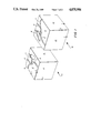
- FIG. 1 is a perspective view on an enlarged scale of two component portions of a fluidic valve module prior to their being bonded in accordance with the present invention.
- FIG. 2 is a flow diagram of the processing steps involved in carrying out the invention.
- FIG. 3 is a perspective view of a portion of the apparatus employed in the bonding process.
- At least one of the materials found to be of value in the present process are the acrylics. They offer the advantages of being strong and durable, transparent, easily machined and if properly prepared, maintain their physical integrity under stress and temperature changes.
- Various types of acrylic materials are available in sheet form which may generally be between from about 1/8 to about 11/2 inches in thickness. Initially, the sheets are cut to the appropriate size of two components of the finished product, which for example, could be two inches square by one inch thick. These are represented as the blocks B 1 and B 2 in FIG. 1.
- the sides 10 and 12 are, for example, each two inches wide and one inch thick.
- the surfaces 2 are two inches square.
- the process steps will be seen in a block diagram.
- the first step is preshrinking. After the parts or components are cut to approximate size, they are preshrunk before being machined. Preshrinking assures that the most accurate dimensions can be maintained in the finished product. If the parts were machined without being preshrunk, subsequent annealing could cause the grooves, channels and other configurations to change dimensionally.
- Preshrinking is not merely a temporary state but once having been preshrunk, the acrylic material retains its dimensional stability even after machining, annealing or other stressful processes. Because of the structure of cast acrylic, shrinkage in two directions results in an increase in size in another. This may be akin to a conservation of volume. In the preshrinking process, the block will shrink along one or two axes and increase along another. This is due to the prestressed molecular structure created during its manufacturing process.
- the block is placed in an annealing oven where it is shrunk in two directions and enlarged in the third. In other words, as seen in FIG. 1, it might decrease in size along the X and Y axes and increase along the Z axis or any combination of two axes.
- a block which is two inches by two along the X and Y axes and one inch along the Z axis is placed in an annealing oven.
- the temperature is raised gradually to approximately 185° F. over a period of about 6 hours where it is maintained for about 8 hours. It is then allowed to cool slowly for about 6 hours. Heat can penetrate a small block more quickly than a large block, the larger the piece, the longer the heating time. The block(s) are then allowed to cool.
- the block retains that size and does not change dimensions in subsequent manufacturing processes. Furthermore subsequent annealing will not add to the shrinking process. In other words, the block becomes stable after preshrinking, it does not drift in dimension.
- the next step is squaring and surfacing the block(s) to prepare their surfaces for further processing.
- This step is performed by machining a block so that its opposite sides are parallel and their contiguous sides are square relative to each other.
- This is performed by conventional machining processes, as for example, by flycutting.
- the orientation of the blocks relative to their original orientation before being cut from the sheet material is immaterial.
- proper surface preparation is essential. Very little stock is removed from the block per pass, in fact the flycutter which rotates at a very high speed, virtually only skims the surface of the block.
- the flycutting technique as practiced today produces a series of microscopically small arcuate hills and valleys in the surface of the work piece. Short of polishing, it is the smoothest surface cutting technique available. Each block of the module is prepared in this manner.
- the next step in the process is the machining of the desired fluidic configuration in one or both of the the interface surfaces. While this step is not essential to effect a bond at the interface, it is necessary to produce a functional valve or manifold.
- the blocks B 1 and B 2 both have their interface surfaces 2 machined with a plurality of channels 4 and 5, pockets 6, and passageways 8, etc.
- both of the surfaces 2 are machined as mirror images of each other. If however, the passageways were formed only as semicircular grooves in the block B 1 when the blocks are assembled, the passageways would be semicircular in cross-section, but when the passageways are formed half from block B 1 and half in that block B 2 the combined passageway is circular in configuration and twice the crosssectional area. If the fluidic pattern is formed in only one of the surfaces 2, say block B 1 for example, when the block B 2 having no machining in its surface 2 is secured to B 1 , each of the passageways, channels, pockets or holes would have one flat side.
- various components such as valves, electronic components and the like can be inserted into the surface 2, as for example by holes being drilled and components pressed into them.
- various materials in sheet form as for example, Mylar--a polyethylene film sold by the duPont Company, may be positioned at the interfaces to subsequently be encapsulated in the assembled module comprising blocks B 1 and B 2 .
- the cutting operation is by conventional machine tools with dimensions being taken from the pre-smoothed and squared surface 2. Note that passageway 5 is curved, having been milled in the surfaces 2.
- the surfaces 2 may be subjected to another or second surfacing treatment, as for example by flycutting. Only a minimum amount of stock is removed from the surface. This is so as not to interfere with the precut fluidic pattern in order to maintain the tolerances of the various channels and grooves 4, 5, 6 and 8. This process step is optional.
- rubber gaskets or O-Rings can be inserted in pre-drilled holes in the surfaces 2 if needed for the operation of the module.
- magnetic stirrers could also be included. This is done preferably by press or forced fitting them into holes to eliminate the need for adhesives which could be detrimental to the fluids or gasses subsequently to flow through the module.
- the second surfacing step not only gets rid of burrs but also improves the overall surface finish. For example, if the initial squaring technique were performed with a heavy cut, the second of the surfacing steps by comparison would be essentially a polishing step.
- the next step to be performed is that of polishing. This is not absolutely essential to all processes but in some instances it is required, for example, where fluid flow requirements dictate that the actual channels or passageways have to be polished. This may be done by conventional polishing processes.
- the actual interface surfaces 2 are polished prior to bonding. This is done primarily to improve the transparency of the ultimate bonded interface. Conversely, if it is desired to assure that the actual channels and passageways 4, 5 and 8 be visible, they would be left unpolished and the interface 2 polished. In the completed bonded module the somewhat greyish machined finish of the channels would make them more visible.
- the polishing step of the interface 2 is performed primarily to make the ultimate bonded interface more clear than if the flycut surfaces were bonded together. Buffing and/or sanding and lapping techniques may be used in polishing the surface as well as the use of chemical vapors. Flame polishing techniques may also be incorporated. Vapor polishing would be used in that case. Vapor polishing is the technique of choice for getting inside small holes.
- the next step in the process is cleaning the surface 2. This may be done as simply as by the use of soap and water or more commonly is done by the commercial ultrasonic Freon Tank Method. Any contaminant or foreign body must be removed from the surfaces such as oil or chips of the acrylic from the machining steps.
- the Freon Tank Method includes a plurality of emersion steps.
- the next process step is defined broadly as confining as seen in FIG. 2.
- a containing fixture 18 It comprises a hollow block 20 having parallel walls 22 and 24. Were the blocks cylindrical, the interior of the fixture would be cylindrical. The inner surfaces 25 and 26 of the walls are perfectly flat. They are just large enough to accept the blocks B 1 and B 2 in a sliding fit. The two blocks B 1 and B 2 are placed and thus combined within the fixture block 20 with their interface surfaces 2 in engagement with each other. The surfaces 10 and the surfaces 12 of the blocks then each constitute a continuous flat surface in engagement with one of the surfaces 25 or 26.
- Inserts 30 which have the same configuration as the opening in the fixture 20 are moved toward each other into the fixture from opposite sides.
- Each of the inserts 30 has a flat surface 32 which engages an opposite side of the block B 1 or B 2 which is parallel to the interface surface 2.
- FIG. 3 shows the fixture schematically with simple handles 34 it will be understood that the inserts 30 can be machined operated. The inserts 30 are moved towards each other to a predetermined stop point pressing against the blocks B 1 and B 2 .
- the fixture 20 may be made of aluminum or any other good heat conducting material.
- the insides 25 and 26 of the walls 22 and 24 are smooth and highly polished since they are to impart a polished appearance to the surface of the acrylic module which comes in engagement with them.
- the inserts 30 Once the inserts 30 have been moved into position to the predetermined stop points and are against the acrylic components B 1 and B 2 , they are not moved further. It is to be emphasized that the inserts 30 do not continuously move during the bonding process but rather, once having be set to a predetermined spaced part distance they remain at that distance. Thus, it will be seen that the assembled module made up of the two components B 1 and B 2 is confined on all six sides or, were it cylindrical, around the cylinder and on its ends.
- the fixture 18, including the inserts 30 and the workpieces B 1 and B 2 are next placed in an annealing oven at a predetermined temperature and for a predetermined amount of time.
- the pressure which the stationary inserts 30 and the walls 24 and 25 apply to the assembled components B 1 and B 2 causes the module to tend to expand normal to the directions of applied pressure which direction is shown by the arrows in FIG. 3.
- the induced pressure also forces the interface surfaces 2 against one another. Simultaneously, pressure builds up at the mating interface of the surfaces 2.
- the pressure is a function of temperature not movement of the inserts 30 which are stationary.
- the bonding input results from temperature increase as distinguished from pressure application because, at the outset, little or no pressure is applied to the module by the walls 25 and 26 and the inserts 30 are only moved against the opposite faces of the assembled module parts B 1 and B 2 with manual pressure. It is the temperature which causes the volumetric expansion of the module that creates the pressure.
- the time of bonding is a function of the mass of the module. As examples, the following times and temperatures have been found to be satisfactory.
- Two pieces B 1 and B 2 each measuring 2.980 inches by 3.063 inches in the X and Y directions were bonded.
- One of the pieces was 0.206 inches thick, i.e., in the Z direction, and the other was 0.396 inches thick. They were heated in an oven at 300° F. with a variance of plus or minus 10° for 30 minutes with no preheating and cooled in ambient air.
- a three layer module was successfully bonded, the outer layers each were 0.395 inches by 1.147 inches in the X and Y directions and 0.087 inches thick, i.e., in the Z direction.
- the inner layer was also 0.395 inches by 1.147 inches but it was 0.210 inches thick in the Z direction. Without preheating, the laminate was placed in an oven at 285° F., with a variance of plus or minus 10°, for 30 minutes and allowed to cool in ambient air.
- the temperature is not exceeded but maintained for the predetermined time. Then the ovens are allowed to cool down. At the completion of the bonding process, the then bonded module is removed from the fixture and it is allowed to cool.
- the module having undergone the application of pressure and temperature is subject to the development of internal stresses which are not desirable and which can be detected by employing cross-polarized light or ethyl acetate testing.
- the stresses are removed by annealing. This is accomplished by subjecting the bonded module to heat for a predetermined period of time.
- the acrylic module at this time, is unconfined.
- the annealing operation takes essentially eight hours at a temperature from about 170° F. to about 200° F. which is substantially lower than the bonding temperature. This causes a "settling" of the molecules of acrylic in their proper resting place, free of unwanted stress.
- any subsequent machining operations may be performed on the module as for example, drilling of screw holes which generally is required for mounting the module. This, in no way affects the bonding which has taken place.
Landscapes
- Engineering & Computer Science (AREA)
- Mechanical Engineering (AREA)
- General Engineering & Computer Science (AREA)
- Computer Hardware Design (AREA)
- Microelectronics & Electronic Packaging (AREA)
- Theoretical Computer Science (AREA)
- Physics & Mathematics (AREA)
- Fluid Mechanics (AREA)
- Lining Or Joining Of Plastics Or The Like (AREA)
Priority Applications (9)
| Application Number | Priority Date | Filing Date | Title |
|---|---|---|---|
| US07/105,607 US4875956A (en) | 1987-10-06 | 1987-10-06 | Method of bonding plastics |
| EP88909141A EP0381692B1 (de) | 1987-10-06 | 1988-10-05 | Verfahren zum verbinden von kunststoffen |
| PCT/US1988/003465 WO1989003297A1 (en) | 1987-10-06 | 1988-10-05 | Method of bonding plastics |
| AT88909141T ATE88133T1 (de) | 1987-10-06 | 1988-10-05 | Verfahren zum verbinden von kunststoffen. |
| JP63508530A JPH03500394A (ja) | 1987-10-06 | 1988-10-05 | プラスチツクを結合する方法 |
| DE8888909141T DE3880319T2 (de) | 1987-10-06 | 1988-10-05 | Verfahren zum verbinden von kunststoffen. |
| CA000579513A CA1294202C (en) | 1987-10-06 | 1988-10-06 | Method of bonding plastics |
| US07/360,267 US4999069A (en) | 1987-10-06 | 1989-06-02 | Method of bonding plastics |
| US07/571,937 US5041181A (en) | 1987-10-06 | 1990-08-23 | Method of bonding plastics |
Applications Claiming Priority (1)
| Application Number | Priority Date | Filing Date | Title |
|---|---|---|---|
| US07/105,607 US4875956A (en) | 1987-10-06 | 1987-10-06 | Method of bonding plastics |
Related Child Applications (1)
| Application Number | Title | Priority Date | Filing Date |
|---|---|---|---|
| US07/360,267 Continuation-In-Part US4999069A (en) | 1987-10-06 | 1989-06-02 | Method of bonding plastics |
Publications (1)
| Publication Number | Publication Date |
|---|---|
| US4875956A true US4875956A (en) | 1989-10-24 |
Family
ID=22306797
Family Applications (1)
| Application Number | Title | Priority Date | Filing Date |
|---|---|---|---|
| US07/105,607 Expired - Fee Related US4875956A (en) | 1987-10-06 | 1987-10-06 | Method of bonding plastics |
Country Status (7)
| Country | Link |
|---|---|
| US (1) | US4875956A (de) |
| EP (1) | EP0381692B1 (de) |
| JP (1) | JPH03500394A (de) |
| AT (1) | ATE88133T1 (de) |
| CA (1) | CA1294202C (de) |
| DE (1) | DE3880319T2 (de) |
| WO (1) | WO1989003297A1 (de) |
Cited By (15)
| Publication number | Priority date | Publication date | Assignee | Title |
|---|---|---|---|---|
| US4999069A (en) * | 1987-10-06 | 1991-03-12 | Integrated Fluidics, Inc. | Method of bonding plastics |
| US5072145A (en) * | 1990-09-05 | 1991-12-10 | Sundstrand Corporation | Composite center module housing using specifically shaped segments to form fluid channels |
| US5496009A (en) * | 1994-10-07 | 1996-03-05 | Bayer Corporation | Valve |
| EP0706004A2 (de) | 1994-10-07 | 1996-04-10 | Bayer Corporation | Entlastungsventil |
| EP0705978A2 (de) | 1994-10-07 | 1996-04-10 | Bayer Corporation | Integrierte Ventildiaphragmpumpe und Verfahren |
| US5788927A (en) * | 1996-07-30 | 1998-08-04 | Bayer Corporation | Unified fluid circuit assembly for a clinical hematology instrument |
| FR2766878A1 (fr) * | 1997-07-31 | 1999-02-05 | Coutier Moulage Gen Ind | Centrale de distribution d'air comprime pour vehicule |
| US5934885A (en) * | 1994-10-07 | 1999-08-10 | Bayer Corporation | Reagent pump assembly |
| US5989481A (en) * | 1996-06-18 | 1999-11-23 | You; Daniel H. | Golf club shaft manufacturing process |
| US6176962B1 (en) | 1990-02-28 | 2001-01-23 | Aclara Biosciences, Inc. | Methods for fabricating enclosed microchannel structures |
| US6317977B1 (en) | 1998-10-26 | 2001-11-20 | Smc Kabushiki Kaisha | Manufacturing method for fluid passage forming member made of synthetic resin |
| US20020053399A1 (en) * | 1996-07-30 | 2002-05-09 | Aclara Biosciences, Inc | Methods for fabricating enclosed microchannel structures |
| EP1069985B1 (de) * | 1998-04-07 | 2004-04-28 | Max-Planck-Gesellschaft zur Förderung der Wissenschaften e.V. | Klebstoff-freie verbindungen von polymerbauteilen zur erzeugung von geschlossenen mikro- und nanokanalstrukturen |
| US20070240496A1 (en) * | 1999-02-20 | 2007-10-18 | Bayer Healthcare Llc | Variable Rate Particle Counter and Method of Use |
| US20080273346A1 (en) * | 2006-11-16 | 2008-11-06 | Hartman David C | Vehicular light assembly and associated method for repairing the same |
Citations (31)
| Publication number | Priority date | Publication date | Assignee | Title |
|---|---|---|---|---|
| US2361589A (en) * | 1940-08-14 | 1944-10-31 | American Optical Corp | Lens |
| US2533609A (en) * | 1949-03-19 | 1950-12-12 | Bell Aircraft Corp | Process for manufacturing minutely orificed articles |
| US2963394A (en) * | 1956-10-19 | 1960-12-06 | Crane Packing Ltd | Joining of elements composed of plastic materials |
| US3016066A (en) * | 1960-01-22 | 1962-01-09 | Raymond W Warren | Fluid oscillator |
| US3144037A (en) * | 1961-02-16 | 1964-08-11 | Sperry Rand Corp | Electro-sonic fluid amplifier |
| US3193424A (en) * | 1961-10-31 | 1965-07-06 | Olin Mathieson | Process for adhesive bonding |
| US3409198A (en) * | 1965-04-30 | 1968-11-05 | Texas Instruments Inc | Bonding apparatus which assures bondability |
| DE1918081A1 (de) * | 1968-04-23 | 1969-11-06 | Bekaert Pvba Leon | Logisches Schaltelement auf Fluidbasis sowie Verfahren und Vorrichtung zu seiner Herstellung |
| US3632841A (en) * | 1970-05-13 | 1972-01-04 | Terry D Fortin | Method of stretching acrylic plastics and product |
| US3645824A (en) * | 1968-10-29 | 1972-02-29 | Morton Int Inc | Process for providing improved polyvinylidene chloride-coated substrates |
| US3647592A (en) * | 1968-07-24 | 1972-03-07 | Mallory & Co Inc P R | Polyester bonding process |
| US3661677A (en) * | 1969-10-10 | 1972-05-09 | Allied Chem | Post-heat treatment for polyvinylidene chloride-coated film |
| US3668756A (en) * | 1968-04-23 | 1972-06-13 | M V Bekaert Sa | Method for making fluid channels |
| US3739055A (en) * | 1969-08-26 | 1973-06-12 | Bridgestone Tire Co Ltd | Method for heat treating polyamide fibers |
| US3814785A (en) * | 1969-01-03 | 1974-06-04 | Ici Ltd | Heat stabilization of oriented thermoplastic films |
| US3872563A (en) * | 1972-11-13 | 1975-03-25 | United Aircraft Corp | Method of blade construction |
| US4211594A (en) * | 1975-11-05 | 1980-07-08 | Sigri Elektrographit Gesellschaft Mit Beschrankter Haftung | Joining together shaped bodies of polytetrafluoroethylene |
| US4240855A (en) * | 1976-12-13 | 1980-12-23 | William Pennington | Method of welding plastic sheets edge-to-edge |
| US4247514A (en) * | 1975-05-05 | 1981-01-27 | E. I. Du Pont De Nemours And Company | Process for strengthening a shaped article of a polyester |
| US4315050A (en) * | 1980-01-25 | 1982-02-09 | Norfield Corporation | Laminates structure of an expanded core panel and a flat sheet of material which does not easily bond and a process for making the same |
| US4339400A (en) * | 1981-05-11 | 1982-07-13 | Sorko Ram Paul A | Process for producing three-dimensional, mirrored acrylic articles |
| US4342071A (en) * | 1977-11-08 | 1982-07-27 | Challenger Diving Limited | Underwater lighting |
| US4355076A (en) * | 1976-08-04 | 1982-10-19 | Koninklijke Emballage Industrie Van Leer, B.V. | Dry lamination |
| US4357190A (en) * | 1978-12-07 | 1982-11-02 | Hancor, Inc. | Method and apparatus for manufacturing non-round plastic tubing |
| US4361527A (en) * | 1981-10-21 | 1982-11-30 | Ppg Industries, Inc. | Method of forming stretched acrylic sheets |
| US4384016A (en) * | 1981-08-06 | 1983-05-17 | Celanese Corporation | Mutiaxially oriented high performance laminates comprised of uniaxially oriented sheets of thermotropic liquid crystal polymers |
| US4390384A (en) * | 1977-12-20 | 1983-06-28 | Hardigg Industries, Inc. | Method and apparatus for bonding thermoplastic materials |
| US4390383A (en) * | 1975-10-03 | 1983-06-28 | Wavin B.V. | Method of making plastic pipes having walls with lengthwise extending channels |
| US4601861A (en) * | 1982-09-30 | 1986-07-22 | Amerace Corporation | Methods and apparatus for embossing a precision optical pattern in a resinous sheet or laminate |
| US4648925A (en) * | 1984-08-01 | 1987-03-10 | Corning Glass Works | Method of making transparent polarizing laminated glasses |
| US4721541A (en) * | 1985-09-26 | 1988-01-26 | Trak Microwave Corporation | Ceramic diffusion bonding method |
Family Cites Families (6)
| Publication number | Priority date | Publication date | Assignee | Title |
|---|---|---|---|---|
| GB580855A (en) * | 1944-02-04 | 1946-09-23 | Charles Hampden Crooks | Removal of stresses from thermoplastic resin articles |
| FR1556088A (de) * | 1967-04-21 | 1969-01-31 | ||
| GB1223661A (en) * | 1969-01-16 | 1971-03-03 | Mess & Regelungst Veb K | Fluid digital system assembly |
| JPS50151971A (de) * | 1974-05-31 | 1975-12-06 | ||
| US4426349A (en) * | 1982-04-08 | 1984-01-17 | Rca Corporation | Process for improving dimensional stability of video disc caddy |
| FR2535337B1 (fr) * | 1982-11-03 | 1985-11-22 | Aceref Applic Chim Electro Res | Procede de liaison d'au moins deux pieces en un materiau qui ne se liquefie pas sous l'influence de la chaleur, tel que le polytetrafluoroethylene |
-
1987
- 1987-10-06 US US07/105,607 patent/US4875956A/en not_active Expired - Fee Related
-
1988
- 1988-10-05 DE DE8888909141T patent/DE3880319T2/de not_active Expired - Fee Related
- 1988-10-05 AT AT88909141T patent/ATE88133T1/de not_active IP Right Cessation
- 1988-10-05 EP EP88909141A patent/EP0381692B1/de not_active Expired - Lifetime
- 1988-10-05 WO PCT/US1988/003465 patent/WO1989003297A1/en not_active Ceased
- 1988-10-05 JP JP63508530A patent/JPH03500394A/ja active Pending
- 1988-10-06 CA CA000579513A patent/CA1294202C/en not_active Expired - Lifetime
Patent Citations (31)
| Publication number | Priority date | Publication date | Assignee | Title |
|---|---|---|---|---|
| US2361589A (en) * | 1940-08-14 | 1944-10-31 | American Optical Corp | Lens |
| US2533609A (en) * | 1949-03-19 | 1950-12-12 | Bell Aircraft Corp | Process for manufacturing minutely orificed articles |
| US2963394A (en) * | 1956-10-19 | 1960-12-06 | Crane Packing Ltd | Joining of elements composed of plastic materials |
| US3016066A (en) * | 1960-01-22 | 1962-01-09 | Raymond W Warren | Fluid oscillator |
| US3144037A (en) * | 1961-02-16 | 1964-08-11 | Sperry Rand Corp | Electro-sonic fluid amplifier |
| US3193424A (en) * | 1961-10-31 | 1965-07-06 | Olin Mathieson | Process for adhesive bonding |
| US3409198A (en) * | 1965-04-30 | 1968-11-05 | Texas Instruments Inc | Bonding apparatus which assures bondability |
| US3668756A (en) * | 1968-04-23 | 1972-06-13 | M V Bekaert Sa | Method for making fluid channels |
| DE1918081A1 (de) * | 1968-04-23 | 1969-11-06 | Bekaert Pvba Leon | Logisches Schaltelement auf Fluidbasis sowie Verfahren und Vorrichtung zu seiner Herstellung |
| US3647592A (en) * | 1968-07-24 | 1972-03-07 | Mallory & Co Inc P R | Polyester bonding process |
| US3645824A (en) * | 1968-10-29 | 1972-02-29 | Morton Int Inc | Process for providing improved polyvinylidene chloride-coated substrates |
| US3814785A (en) * | 1969-01-03 | 1974-06-04 | Ici Ltd | Heat stabilization of oriented thermoplastic films |
| US3739055A (en) * | 1969-08-26 | 1973-06-12 | Bridgestone Tire Co Ltd | Method for heat treating polyamide fibers |
| US3661677A (en) * | 1969-10-10 | 1972-05-09 | Allied Chem | Post-heat treatment for polyvinylidene chloride-coated film |
| US3632841A (en) * | 1970-05-13 | 1972-01-04 | Terry D Fortin | Method of stretching acrylic plastics and product |
| US3872563A (en) * | 1972-11-13 | 1975-03-25 | United Aircraft Corp | Method of blade construction |
| US4247514A (en) * | 1975-05-05 | 1981-01-27 | E. I. Du Pont De Nemours And Company | Process for strengthening a shaped article of a polyester |
| US4390383A (en) * | 1975-10-03 | 1983-06-28 | Wavin B.V. | Method of making plastic pipes having walls with lengthwise extending channels |
| US4211594A (en) * | 1975-11-05 | 1980-07-08 | Sigri Elektrographit Gesellschaft Mit Beschrankter Haftung | Joining together shaped bodies of polytetrafluoroethylene |
| US4355076A (en) * | 1976-08-04 | 1982-10-19 | Koninklijke Emballage Industrie Van Leer, B.V. | Dry lamination |
| US4240855A (en) * | 1976-12-13 | 1980-12-23 | William Pennington | Method of welding plastic sheets edge-to-edge |
| US4342071A (en) * | 1977-11-08 | 1982-07-27 | Challenger Diving Limited | Underwater lighting |
| US4390384A (en) * | 1977-12-20 | 1983-06-28 | Hardigg Industries, Inc. | Method and apparatus for bonding thermoplastic materials |
| US4357190A (en) * | 1978-12-07 | 1982-11-02 | Hancor, Inc. | Method and apparatus for manufacturing non-round plastic tubing |
| US4315050A (en) * | 1980-01-25 | 1982-02-09 | Norfield Corporation | Laminates structure of an expanded core panel and a flat sheet of material which does not easily bond and a process for making the same |
| US4339400A (en) * | 1981-05-11 | 1982-07-13 | Sorko Ram Paul A | Process for producing three-dimensional, mirrored acrylic articles |
| US4384016A (en) * | 1981-08-06 | 1983-05-17 | Celanese Corporation | Mutiaxially oriented high performance laminates comprised of uniaxially oriented sheets of thermotropic liquid crystal polymers |
| US4361527A (en) * | 1981-10-21 | 1982-11-30 | Ppg Industries, Inc. | Method of forming stretched acrylic sheets |
| US4601861A (en) * | 1982-09-30 | 1986-07-22 | Amerace Corporation | Methods and apparatus for embossing a precision optical pattern in a resinous sheet or laminate |
| US4648925A (en) * | 1984-08-01 | 1987-03-10 | Corning Glass Works | Method of making transparent polarizing laminated glasses |
| US4721541A (en) * | 1985-09-26 | 1988-01-26 | Trak Microwave Corporation | Ceramic diffusion bonding method |
Non-Patent Citations (2)
| Title |
|---|
| L. S. Luskin, "Acrylic", Modern Plastics Encyclopedia, 1983-1984, pp. 14-18. |
| L. S. Luskin, Acrylic , Modern Plastics Encyclopedia, 1983 1984, pp. 14 18. * |
Cited By (21)
| Publication number | Priority date | Publication date | Assignee | Title |
|---|---|---|---|---|
| US4999069A (en) * | 1987-10-06 | 1991-03-12 | Integrated Fluidics, Inc. | Method of bonding plastics |
| US6176962B1 (en) | 1990-02-28 | 2001-01-23 | Aclara Biosciences, Inc. | Methods for fabricating enclosed microchannel structures |
| US5072145A (en) * | 1990-09-05 | 1991-12-10 | Sundstrand Corporation | Composite center module housing using specifically shaped segments to form fluid channels |
| US5902096A (en) * | 1994-10-07 | 1999-05-11 | Bayer Corporation | Diaphragm pump having multiple rigid layers with inlet and outlet check valves |
| EP0705978A2 (de) | 1994-10-07 | 1996-04-10 | Bayer Corporation | Integrierte Ventildiaphragmpumpe und Verfahren |
| EP0706003A3 (de) * | 1994-10-07 | 1997-03-05 | Bayer Ag | Membranventil |
| US5669764A (en) * | 1994-10-07 | 1997-09-23 | Bayer Corporation | Pneumatic diaphragm pump |
| EP0706004A2 (de) | 1994-10-07 | 1996-04-10 | Bayer Corporation | Entlastungsventil |
| US5496009A (en) * | 1994-10-07 | 1996-03-05 | Bayer Corporation | Valve |
| EP0706003A2 (de) | 1994-10-07 | 1996-04-10 | Bayer Corporation | Membranventil |
| US5934885A (en) * | 1994-10-07 | 1999-08-10 | Bayer Corporation | Reagent pump assembly |
| US5989481A (en) * | 1996-06-18 | 1999-11-23 | You; Daniel H. | Golf club shaft manufacturing process |
| US5788927A (en) * | 1996-07-30 | 1998-08-04 | Bayer Corporation | Unified fluid circuit assembly for a clinical hematology instrument |
| US20020053399A1 (en) * | 1996-07-30 | 2002-05-09 | Aclara Biosciences, Inc | Methods for fabricating enclosed microchannel structures |
| FR2766878A1 (fr) * | 1997-07-31 | 1999-02-05 | Coutier Moulage Gen Ind | Centrale de distribution d'air comprime pour vehicule |
| EP1069985B1 (de) * | 1998-04-07 | 2004-04-28 | Max-Planck-Gesellschaft zur Förderung der Wissenschaften e.V. | Klebstoff-freie verbindungen von polymerbauteilen zur erzeugung von geschlossenen mikro- und nanokanalstrukturen |
| US6317977B1 (en) | 1998-10-26 | 2001-11-20 | Smc Kabushiki Kaisha | Manufacturing method for fluid passage forming member made of synthetic resin |
| DE19951662C2 (de) * | 1998-10-26 | 2002-01-10 | Smc Corp | Verfahren zur Herstellung eines Fluiddurchgangsformelements aus Kunstharz |
| US20070240496A1 (en) * | 1999-02-20 | 2007-10-18 | Bayer Healthcare Llc | Variable Rate Particle Counter and Method of Use |
| US20080273346A1 (en) * | 2006-11-16 | 2008-11-06 | Hartman David C | Vehicular light assembly and associated method for repairing the same |
| US8136971B2 (en) * | 2006-11-16 | 2012-03-20 | Hartman David C | Vehicular light assembly and associated method for repairing the same |
Also Published As
| Publication number | Publication date |
|---|---|
| EP0381692B1 (de) | 1993-04-14 |
| ATE88133T1 (de) | 1993-04-15 |
| WO1989003297A1 (en) | 1989-04-20 |
| JPH03500394A (ja) | 1991-01-31 |
| CA1294202C (en) | 1992-01-14 |
| DE3880319T2 (de) | 1993-07-29 |
| EP0381692A1 (de) | 1990-08-16 |
| DE3880319D1 (de) | 1993-05-19 |
Similar Documents
| Publication | Publication Date | Title |
|---|---|---|
| US5041181A (en) | Method of bonding plastics | |
| US4999069A (en) | Method of bonding plastics | |
| EP0381692B1 (de) | Verfahren zum verbinden von kunststoffen | |
| AU678612B2 (en) | Shaped plastic light-polarizing lens and method of making same | |
| US4902365A (en) | Method for making a composite sheet-like structure | |
| US20020175265A1 (en) | Diffusion bonded tooling with conformal cooling | |
| Kagan et al. | Laser transmission welding of semicrystalline thermoplastics-Part II: Analysis of mechanical performance of welded nylon | |
| Cassano et al. | Use of vacuum bagging for fabricating thermoplastic microfluidic devices | |
| EP0891575A1 (de) | Linseerohrlinge mit ausgerichtetem polarisator | |
| JPH07195392A (ja) | フッ素樹脂を表面材とするインサート成形体の製造法 | |
| Stokes | Experiments on the hot-tool welding of three dissimilar thermoplastics | |
| US5707477A (en) | Model and method for fabricating same | |
| US6317977B1 (en) | Manufacturing method for fluid passage forming member made of synthetic resin | |
| US20250196130A1 (en) | Fluid Device and Method for Manufacturing Fluid Devices | |
| EP2653285A1 (de) | Bereitstellung von Mikrokanälen in einem Kunststoffsubstrat | |
| JPS6235897A (ja) | 装飾的器具及びその製造方法 | |
| US20020164201A1 (en) | Method and apparatus for butt-jointing profiles made of elastomeric material | |
| Stokes | Comparison of vibration and hot‐tool thermoplastic weld morphologies | |
| DE102023208313A1 (de) | Verfahren, Spannwerkzeug und Vorrichtung für das Laserdurchstrahlfügen | |
| JPH05345357A (ja) | プラスチック部品の接合方法 | |
| Walczyk et al. | Bonding methods for laminated tooling | |
| CN219998327U (zh) | 换热器、电池包和车辆 | |
| CN117087105A (zh) | 具有冷却功能的细长件及其制作方法 | |
| Kagan et al. | Selecting nylon-based plastics for laser welding technology | |
| EP4434731B1 (de) | Werkzeuge und verfahren zur herstellung von thermoplastischen platten |
Legal Events
| Date | Code | Title | Description |
|---|---|---|---|
| AS | Assignment |
Owner name: INTEGRATED FLUIDICS, INC., 93 WEST MAIN STREET, PL Free format text: ASSIGNMENT OF ASSIGNORS INTEREST.;ASSIGNOR:BRACKETT, TOM S.;REEL/FRAME:004827/0838 Effective date: 19880203 Owner name: INTEGRATED FLUIDICS, INC., A CORP. OF CT.,CONNECT Free format text: ASSIGNMENT OF ASSIGNORS INTEREST;ASSIGNOR:BRACKETT, TOM S.;REEL/FRAME:004827/0838 Effective date: 19880203 |
|
| AS | Assignment |
Owner name: INTEGRATED FLUIDICS COMPANY, CONNECTICUT Free format text: ASSIGNMENT OF ASSIGNORS INTEREST.;ASSIGNORS:BRACKETT, TOM S.;BRACKETT, ERNEST;BRACKETT, JEFF;AND OTHERS;REEL/FRAME:005175/0666 Effective date: 19891026 Owner name: BRACKETT, TOM (16.66%), CONNECTICUT Free format text: ASSIGNMENT OF A PART OF ASSIGNORS INTEREST;ASSIGNOR:INTEGRATED FLUIDICS, INC.;REEL/FRAME:005175/0833 Effective date: 19891026 Owner name: BRACKETT, JEFF (16.67%), CONNECTICUT Free format text: ASSIGNOR ASSIGNS ASSIGNEES THE INTEREST OPPOSITE THEIR RESPECTIVE NAMES.;ASSIGNOR:INTEGRATED FLUIDICS, INC.;REEL/FRAME:005178/0929 Effective date: 19891026 Owner name: WEBSTER, MILO E. (25%), MASSACHUSETTS Free format text: ASSIGNMENT OF A PART OF ASSIGNORS INTEREST;ASSIGNOR:INTEGRATED FLUIDICS, INC.;REEL/FRAME:005175/0833 Effective date: 19891026 Owner name: BRACKETT, ERNEST (25%), CONNECTICUT Free format text: ASSIGNMENT OF A PART OF ASSIGNORS INTEREST;ASSIGNOR:INTEGRATED FLUIDICS, INC.;REEL/FRAME:005175/0833 Effective date: 19891026 Owner name: WEBSTER, MILO E. (25%), MASSACHUSETTS Free format text: ASSIGNOR ASSIGNS ASSIGNEES THE INTEREST OPPOSITE THEIR RESPECTIVE NAMES.;ASSIGNOR:INTEGRATED FLUIDICS, INC.;REEL/FRAME:005178/0929 Effective date: 19891026 Owner name: BRACKETT, SCOTT (16.67%), CONNECTICUT Free format text: ASSIGNOR ASSIGNS ASSIGNEES THE INTEREST OPPOSITE THEIR RESPECTIVE NAMES.;ASSIGNOR:INTEGRATED FLUIDICS, INC.;REEL/FRAME:005178/0929 Effective date: 19891026 Owner name: BRACKETT, ERNEST (25%), CONNECTICUT Free format text: ASSIGNOR ASSIGNS ASSIGNEES THE INTEREST OPPOSITE THEIR RESPECTIVE NAMES.;ASSIGNOR:INTEGRATED FLUIDICS, INC.;REEL/FRAME:005178/0929 Effective date: 19891026 Owner name: BRACKETT, TOM (16.66%), CONNECTICUT Free format text: ASSIGNOR ASSIGNS ASSIGNEES THE INTEREST OPPOSITE THEIR RESPECTIVE NAMES.;ASSIGNOR:INTEGRATED FLUIDICS, INC.;REEL/FRAME:005178/0929 Effective date: 19891026 Owner name: BRACKETT, JEFF (16.67%), CONNECTICUT Free format text: ASSIGNMENT OF A PART OF ASSIGNORS INTEREST;ASSIGNOR:INTEGRATED FLUIDICS, INC.;REEL/FRAME:005175/0833 Effective date: 19891026 Owner name: INTEGRATED FLUIDICS COMPANY,, CONNECTICUT Free format text: ASSIGNMENT OF ASSIGNORS INTEREST.;ASSIGNORS:WEBSTER, MILO E.;BRACKETT, ERNEST;BRACKETT, JEFF;AND OTHERS;REEL/FRAME:005195/0978 Effective date: 19891026 Owner name: BRACKETT, SCOTT (16.67%), CONNECTICUT Free format text: ASSIGNMENT OF A PART OF ASSIGNORS INTEREST;ASSIGNOR:INTEGRATED FLUIDICS, INC.;REEL/FRAME:005175/0833 Effective date: 19891026 |
|
| FPAY | Fee payment |
Year of fee payment: 4 |
|
| REMI | Maintenance fee reminder mailed | ||
| LAPS | Lapse for failure to pay maintenance fees | ||
| FP | Lapsed due to failure to pay maintenance fee |
Effective date: 19971029 |
|
| STCH | Information on status: patent discontinuation |
Free format text: PATENT EXPIRED DUE TO NONPAYMENT OF MAINTENANCE FEES UNDER 37 CFR 1.362 |