US487750A - Windmill - Google Patents
Windmill Download PDFInfo
- Publication number
- US487750A US487750A US487750DA US487750A US 487750 A US487750 A US 487750A US 487750D A US487750D A US 487750DA US 487750 A US487750 A US 487750A
- Authority
- US
- United States
- Prior art keywords
- wheel
- spokes
- windmill
- rim
- hub
- Prior art date
- Legal status (The legal status is an assumption and is not a legal conclusion. Google has not performed a legal analysis and makes no representation as to the accuracy of the status listed.)
- Expired - Lifetime
Links
Images


Classifications
-
- F—MECHANICAL ENGINEERING; LIGHTING; HEATING; WEAPONS; BLASTING
- F01—MACHINES OR ENGINES IN GENERAL; ENGINE PLANTS IN GENERAL; STEAM ENGINES
- F01D—NON-POSITIVE DISPLACEMENT MACHINES OR ENGINES, e.g. STEAM TURBINES
- F01D5/00—Blades; Blade-carrying members; Heating, heat-insulating, cooling or antivibration means on the blades or the members
- F01D5/12—Blades
- F01D5/22—Blade-to-blade connections, e.g. for damping vibrations
Definitions
- My invention relates to that class of machines which are designed to utilize the force or power of atmospheric currents for operating pumps and various other types of machinery; and its obj ects are to produce a windmill which shall be, simple, durable, and inexpensive and also very light in construction and which shall be entirely uniform and automatic in its operation, and, furthermore, the parts of which can be readily connected together and disconnected from each other whenever necessary in setting ,up, taking down, or shipping the machine.
- a still further object of my invention is to produce a windmill the wheel of which can be quicklyand easily turned Whenever necessary and to provide means for quickly and easily throwing the windmill into and out.
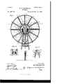
- FIG. l is a front elevation of a windmill constructed in accordance with my invention, the vanesbeing set open, so as to stop the rotation of the wind-wheel.
- Fig. 2 is a transverse vertical section'of the same ou the line 2 2 of Fig. l.
- Fig. 3 is a horizontal cross-section of the same on the line 3 3 of Fig. l, the vanes being, however, set in their normal oblique operative positions.
- Fig. 4 is a transverse vertical section of the same on the line 4 4 of Fig. 3.
- Fig. 2 is a transverse vertical section'of the same ou the line 2 2 of Fig. l.
- Fig. 3 is a horizontal cross-section of the same on the line 3 3 of Fig. l, the vanes being, however, set in their normal oblique operative positions.
- Fig. 4 is a transverse vertical section of the same on the line 4 4 of Fig. 3.
- FIG. 5 is a perspective view of the central portion of the wind-wheel and its immediate operate connections, the vanes of the Wheel being in this figure also set in their normal oblique operative positions.
- Fig. 6 is a transverse sectional view of the hub and two of the opposite spokes of the wind-wheel on the line 6 6 of Fig. l.
- Fig. 7 is a transverse sectional View of the rim and an outer end of one of the spokes of the wind-wheel on the line 7 7 of Fig. l.
- Fig. 8 is a perspective view of the upper parts of the tower-up rights and the annular cap supported thereby.
- Fig. 9 is a view, partly in side elevation and partly in central transverse vertical section, of the upper parts of the lower uprights and the cap and head.
- l designates four uprights, which constitute the principal supports of the framework or tower of the windmill, the said supports being of any desired length to'accord with the required elevation of the wind-wheel.
- These uprights converge upwardly and are braced together by any suitable number of horizontal crossbraces 2 and also by any suit.- able number of interposed oblique braces 3, which are arranged in X form.
- annular cap 4,Which is preferably in the form 0f a metal casting and which is provided with a short pendent cylindrical flange 5, which is also preferably in the form of a metal casting integral with the cap 4 just described.
- this flange Upon its outer sides this flange is formed with four pairs of vertical ribs 6, each pair of said ribs thus inclosing a vertical space which constitutes a socket for the reception of the upper end of one of the uprights'l. These uprights are retained in said sockets by any suitable number of through-bolts 7, which pass transversely through the upper ends cf the uprights l and also similarly through the two companion ribs 6.
- a vertical cylinder which is also preferably in the form of a metal casting and which extends downward within the short cylinder 5 and which is also of such length as to extend above the annular cap 4, as is clearly shown in Figs. 2, 4, and 9.
- the upper portion of this cylinder is surrounded by a horizontal head 9, which rests directly upon the annular cap 4 and turns horizontally thereon, the said head being preferably also in the form of a metalcasting,but being permissibly of Wood or other suitable material, and said cylinder is secured to the head by any num ber of bolts ll, which are passed horizontally IOO through the upper part of the cylinder and likewise through the body of the head, as
- this head 9 Upon the upper side ot this head 9 are secured two oppositely-disposed vertical standards or pillow-blocks 12, upon the upper sides of which are secured two journal-bearings 13 for the main shaft 14 of the windwheel.
- rollers 17 From the lower end of the cylinder 3 depend two lugs or ears 15, transversely through which extend two bolts or similar stub-axles 16. Upon the inner ends of these bolts or stub-axles are mounted rollers 17, the peripheries of which come into contact with the under or lower end of the cylinder 8. The purpose of these rollers will be more clearly understood from the ensuing description of the windwheel itself; but it is to be understood thatsaid rollers counteract the friction which might result from uneven balancing of the parts connected to the main shaft 14, which might otherwise cause the cylinder S to bind within the flange 5.
- the main shaft 14 of the windmill is prevented from longitudinal movement (while yet beingpermitted to freely rotate) by two collars 13, which embrace opposite sides of the rear bearing 13.
- the main operating-rod 21 of the windmill To the eccentric-strap 2O is connected, either by an eye 22 or in other suitable manner, the main operating-rod 21 of the windmill, said rod extending downward and havingits lower end bifureated, preferably, as at 23, to embrace the rod 24 of a suitable pump 25.
- the windmill either to any type of pump or to any other machine or machinery capable of being driven by a windmill, and it will therefore be seen that the precise described form of connection at the lower end of the rod 21 maybe varied, as circumstances may suggest.
- the main shaft 14 ofthewindmill is extended rearwardly as far as desired, and at its rear end or portion said shaft carries a balance-wheel 26, the arrangement being such that the extended portion of the main shaft and its balance-wheel shall about counterbalance the front portion of the main shaft and the wind-wheel mounted thereon in order to reduce the friction between the pendent iiange 5 and the cylinder 8 to the minimum.
- This balance-wheel 27 is provided near its periphery with acounterweightor enlargement 27, which extends precisely opposite from the outer end of the longer axis of the eccentric 19, as is clearly shown in Fig. 2.
- the counterweight or the enlargement 27 of the wheel 2G counterbalances the eccentric and renders it impossible for the windmill to stop on a dead-center.
- the wind-wheel itself is constructed as fol lows:
- the hub of the wheel designates the hub of the wheel, which is preferably in the form of a solid metal casting of disk-like form and havingits front side formed with a forwardly-projecting extension 2S) of less diameter than the hub itself.
- the front end of the main shaft 14 passes entirely through the hub and its extension, and said hub is retained removably upon the shaft by a set-bolt 30, which extends radially through the extension 29 and impinges upon the shaft, or by equivalent means, such as a key.
- the rim of the wind-wheel designates the rim of the wind-wheel, the said rim being in the form of a broad circular band which is of suitable diameter and which is preferably of thin steel, so as to combine the maximum degrees of strength with lightness.
- a circular band 32 which is also of metal and which is of much less width and diameter than the rim 31, while of considerably-greater diameter than the hub 28, as indicated in the drawings.
- spokes of t-he wheel designates the spokes of t-he wheel, the said spokes being preferably of hollow tubular material-such as gas-pipe-and having their inner ends 3l externallyscrew-threaded to enter correspondingly internally-screwthreaded radial sockets 35 in the hub 2S.
- These spokes extend radially outward from the hub 2S, and their outer extremities pass through the rim 31 and also through acircular strengthening-rib 3G, which is formed upon or suitably secured to the inner surface of the rim31 midway of its width.
- the outer extremities of these spokes are internally screwthreaded for a suitable distance, as shown at 37, (see Fig.
- These radial arms are of similar hollow character to the spokes 33, and their outer ends are secured to the rim 31 in the same manner-that is, by set-bolts like the setbolts 38-as are the outer ends of the spokes 33; but the arms 40 are of less length than the spokes 33, so that the inner ends of said arms merely pass through the band 32 and are secured in position by nuts 41, which are screwed upon the inner ends of thearms 40 and which abut against the inner surface of the band Upon these arms 40 and the outer portions of the spokes 33 are pivotally mounted the wind-wheel vanes 42, each of which is of substantially-triangular form and of such length as to extend from the inner surface of the rim 31 to the outersurface of the band 32.
- These Vanes are preferably in the form of steel plates, each of which is provided witha IOO IIO
- longitudinal central strengthening-rib 43 formed upon or suitably secured to one side of thevane, and the outer and inner ends ot which are turned at right angles to form flanges 44, through which extend the spokes a single disk-like metal casting and which is arranged to rotate with and also to slide longitudinally upon said main shaft.
- a band 49 which.is similar in respect to material, width,and diameter to the band 32, above described, and which is connected to said hub by a number of radial arms 50.
- These arms 50 are preferably of hollow tubular form, similarly as are the arms 40 and the spokes 33, and the inner ends of said arms 50 are screwed into radial sockets in the margin of said sleeve, while the outer ends of said arms are riveted or otherwise secured to the band 49.
- the rear ends of the links 47 are secured to the' band 49 by rivets 5l or equivalent means.
- a standard or Vertical bracket 52 Upon the front side of the front standard or pillow-block l2 is bolted a standard or Vertical bracket 52, while upon the rear sideof the rear standard or pillow-block is bolted or otherwise secured a second vertical standard 53, bolts 54 serving as the means for thus securing said standards or brackets to the'standards or pillow-block, and said vertical standards or brackets being of such length as to extend downward along the sides of the head 9, as well as those of the pillow-block, and the bolts 54 and the standards 52 and 53 serving, therefore, to assist in securing the pillowblocks to the head.
- the upper part of the standard 53 is, moreover, of U form transversely, and its sides are formed at their lower ends with oppositely and outwardly extending flanges 55, which are secured to the upper side of the corresponding pillow-block by bolts 56.
- the sleeve 48 is formed with an integral-externally-grooved extension 57, in which works loosely a ring 58, said ring being embraced by a bifurcated arm or fork 59, the ends of which are pivotally connected, as at 6l, to the ring.
- the fork 59 is formed upon or secured to the lower end of the vertical front arm of an L-shaped bar 60, the upper arm of which extends rearwardly and horizontally through the upper ends of the brackets 52 and 53, so as to be movable longitudinally therein.
- the rear end of this arm projects considerably beyond the rear bracket 53 and is surrounded by a spiral spring 62, which is confined between the rear side of the rear bracket 53 and a cross-pin 63 or a suitable of the arm.
- the spring 62 is an expansively-acting spring, its expansion tending to draw the bar rearward and through the described connections to retain the vanes in closed position.
- a bell-crank lever 64 is pivoted, as at 65, upon the upper part of the rear bracket 53, and to the upper end of this lever is pivotally connected the rear end of a link 65, the front end of which is pivoted, as at 66, to the bar 60 at a point about midway between the brackets 52 and 53.
- the upper end of a rod 67 To the outer end ot the lower arm of the bell-crank lever 64 is connected the upper end of a rod 67, to the lower end of which is also connected Va cord 67, the lower end of said cord extending within convenient reach ot a person standing upon the ground. It will thus be seen that by pulling downward upon the rod or cord 67 the bar 60 will be moved forward longitudinally, compressing the spring 62, and thus throwing the vanes into open position and stopping the revolution of the wind-wheel.
- the lower end of the rod or cord 67 is shown as provided with a loop 68, which is to be engaged with a suitable peg or pin to retain the wheel in inoperative position as long as desired.
- rollers 69 are journaled in the under side ofthe head 9, as shown, and travel upon the circular casting 4 in the top of the windmill-tower.
- a windmill comprising a wind-wheel hav ing a central hub, a circular rim concentric with the hub, and a circular band intermediate of the hub and rim and concentric therewith, a number of shorterhollow radial spokes interposed between the rim and band and internally screw-threaded at their inner and outer ends, a number of bolts having exter- IOO IIO
Landscapes
- Engineering & Computer Science (AREA)
- Mechanical Engineering (AREA)
- General Engineering & Computer Science (AREA)
- Wind Motors (AREA)
Description
(No Model.) 3 Sheets-Sheet 1.
W. P. KIMBRBLL.
WINDMILL.
No. 487,750. Patented Dec. 13, 1892.
(No Model.) 3 Sheets-Sheet 2. l W. P. KIlVIBRllELL.Y
WINDMILL.
Patented De. 13
W.; um# #.W
(No Model.) f s sheets-sheet 3.
W. P. KIMBRBLL.
WINDMILL.
Patented Deo. 13, 1892.
2a La. u?
Kaff/amy@ UNITED STATES PATENT OFFICE.
4WILLIAM P. KIMBRELL, OF BEAVER CITY, NEBRASKA.
WINDMILL.
SPECIFICATION forming part of Letters Patent No. 487,7 50, dated December 13, 1892.
Application led December 7, 1891. Serial No. 414,217- (NO 111011910 To a/ZZ whom, it may concern.'
Be it known that I, WILLIAM P. KIMBRELL, of Beaver City, Furnas county, Nebraska, have invented certain new and useful Improvements in W'indmills, of which the following is a full, clear, and exact description, reference being had to the accompanying drawings, forming a part hereof.
My invention relates to that class of machines which are designed to utilize the force or power of atmospheric currents for operating pumps and various other types of machinery; and its obj ects are to produce a windmill which shall be, simple, durable, and inexpensive and also very light in construction and which shall be entirely uniform and automatic in its operation, and, furthermore, the parts of which can be readily connected together and disconnected from each other whenever necessary in setting ,up, taking down, or shipping the machine.
A still further object of my invention is to produce a windmill the wheel of which can be quicklyand easily turned Whenever necessary and to provide means for quickly and easily throwing the windmill into and out. of
action, as required.
To the above purposes my invention consists in certain peculiar and novel features of construction and arrangement, as hereinafter described and claimed.
In order that my invention may be fully understood, I will proceed to describe it with reference to the accompanying drawings, in which- Figure l is a front elevation of a windmill constructed in accordance with my invention, the vanesbeing set open, so as to stop the rotation of the wind-wheel. Fig. 2 is a transverse vertical section'of the same ou the line 2 2 of Fig. l. Fig. 3 is a horizontal cross-section of the same on the line 3 3 of Fig. l, the vanes being, however, set in their normal oblique operative positions. Fig. 4 is a transverse vertical section of the same on the line 4 4 of Fig. 3. Fig. 5 is a perspective view of the central portion of the wind-wheel and its immediate operate connections, the vanes of the Wheel being in this figure also set in their normal oblique operative positions. Fig. 6 is a transverse sectional view of the hub and two of the opposite spokes of the wind-wheel on the line 6 6 of Fig. l. Fig. 7 is a transverse sectional View of the rim and an outer end of one of the spokes of the wind-wheel on the line 7 7 of Fig. l. Fig. 8 isa perspective view of the upper parts of the tower-up rights and the annular cap supported thereby. Fig. 9 is a view, partly in side elevation and partly in central transverse vertical section, of the upper parts of the lower uprights and the cap and head.
In the drawings, l designates four uprights, which constitute the principal supports of the framework or tower of the windmill, the said supports being of any desired length to'accord with the required elevation of the wind-wheel. These uprights converge upwardly and are braced together by any suitable number of horizontal crossbraces 2 and also by any suit.- able number of interposed oblique braces 3, which are arranged in X form. Upon the upper ends of these supports l is supported an annular cap 4,Which is preferably in the form 0f a metal casting and which is provided with a short pendent cylindrical flange 5, which is also preferably in the form of a metal casting integral with the cap 4 just described. Upon its outer sides this flange is formed with four pairs of vertical ribs 6, each pair of said ribs thus inclosing a vertical space which constitutes a socket for the reception of the upper end of one of the uprights'l. These uprights are retained in said sockets by any suitable number of through-bolts 7, which pass transversely through the upper ends cf the uprights l and also similarly through the two companion ribs 6.
8 designates a vertical cylinder, which is also preferably in the form of a metal casting and which extends downward within the short cylinder 5 and which is also of such length as to extend above the annular cap 4, as is clearly shown in Figs. 2, 4, and 9. The upper portion of this cylinder is surrounded by a horizontal head 9, which rests directly upon the annular cap 4 and turns horizontally thereon, the said head being preferably also in the form of a metalcasting,but being permissibly of Wood or other suitable material, and said cylinder is secured to the head by any num ber of bolts ll, which are passed horizontally IOO through the upper part of the cylinder and likewise through the body of the head, as
shown. Upon the upper side ot this head 9 are secured two oppositely-disposed vertical standards or pillow-blocks 12, upon the upper sides of which are secured two journal-bearings 13 for the main shaft 14 of the windwheel.
From the lower end of the cylinder 3 depend two lugs or ears 15, transversely through which extend two bolts or similar stub-axles 16. Upon the inner ends of these bolts or stub-axles are mounted rollers 17, the peripheries of which come into contact with the under or lower end of the cylinder 8. The purpose of these rollers will be more clearly understood from the ensuing description of the windwheel itself; but it is to be understood thatsaid rollers counteract the friction which might result from uneven balancing of the parts connected to the main shaft 14, which might otherwise cause the cylinder S to bind within the flange 5. The main shaft 14 of the windmill is prevented from longitudinal movement (while yet beingpermitted to freely rotate) by two collars 13, which embrace opposite sides of the rear bearing 13.
Upon the shaft 14, at a point midway between the bearings 13, is secured an eccentric 19, which is surrounded by the usual divided eccentric-strap, 20.
To the eccentric-strap 2O is connected, either by an eye 22 or in other suitable manner, the main operating-rod 21 of the windmill, said rod extending downward and havingits lower end bifureated, preferably, as at 23, to embrace the rod 24 of a suitable pump 25. Itis to be understood, of course, that l propose to connect the windmill either to any type of pump or to any other machine or machinery capable of being driven by a windmill, and it will therefore be seen that the precise described form of connection at the lower end of the rod 21 maybe varied, as circumstances may suggest. The main shaft 14 ofthewindmill is extended rearwardly as far as desired, and at its rear end or portion said shaft carries a balance-wheel 26, the arrangement being such that the extended portion of the main shaft and its balance-wheel shall about counterbalance the front portion of the main shaft and the wind-wheel mounted thereon in order to reduce the friction between the pendent iiange 5 and the cylinder 8 to the minimum. This balance-wheel 27 is provided near its periphery with acounterweightor enlargement 27, which extends precisely opposite from the outer end of the longer axis of the eccentric 19, as is clearly shown in Fig. 2. Thus the counterweight or the enlargement 27 of the wheel 2G counterbalances the eccentric and renders it impossible for the windmill to stop on a dead-center.
The wind-wheel itself is constructed as fol lows:
28 designates the hub of the wheel, which is preferably in the form of a solid metal casting of disk-like form and havingits front side formed with a forwardly-projecting extension 2S) of less diameter than the hub itself. The front end of the main shaft 14 passes entirely through the hub and its extension, and said hub is retained removably upon the shaft by a set-bolt 30, which extends radially through the extension 29 and impinges upon the shaft, or by equivalent means, such as a key.
31 designates the rim of the wind-wheel, the said rim being in the form of a broad circular band which is of suitable diameter and which is preferably of thin steel, so as to combine the maximum degrees of strength with lightness.
Between the rim and the hub of the windwheel is interposed a circular band 32, which is also of metal and which is of much less width and diameter than the rim 31, while of considerably-greater diameter than the hub 28, as indicated in the drawings.
33 designates the spokes of t-he wheel, the said spokes being preferably of hollow tubular material-such as gas-pipe-and having their inner ends 3l externallyscrew-threaded to enter correspondingly internally-screwthreaded radial sockets 35 in the hub 2S. (See Fig. 6.) These spokes extend radially outward from the hub 2S, and their outer extremities pass through the rim 31 and also through acircular strengthening-rib 3G, which is formed upon or suitably secured to the inner surface of the rim31 midway of its width. The outer extremities of these spokes are internally screwthreaded for a suitable distance, as shown at 37, (see Fig. 7,) and into these ends of the spokes are inserted the externall y screw threaded stems of a corresponding number of the setbolts 38, the heads 39 of said bolts abutting against the outer surface of the rim. It will thus be seen that by turning the set-bolts 38 in one or the opposite direction the rim 31 can be readily and elfectually trued whenever for any cause it has sprung out of the true, or, in other words, out of exact concentric position relative to the hub 28. It is to be observed that these spokes 33 also pass through the intermediate band 32 and that between each two adjacent spokes 33 is interposed a radial arm 10. These radial arms are of similar hollow character to the spokes 33, and their outer ends are secured to the rim 31 in the same manner-that is, by set-bolts like the setbolts 38-as are the outer ends of the spokes 33; but the arms 40 are of less length than the spokes 33, so that the inner ends of said arms merely pass through the band 32 and are secured in position by nuts 41, which are screwed upon the inner ends of thearms 40 and which abut against the inner surface of the band Upon these arms 40 and the outer portions of the spokes 33 are pivotally mounted the wind-wheel vanes 42, each of which is of substantially-triangular form and of such length as to extend from the inner surface of the rim 31 to the outersurface of the band 32. These Vanes are preferably in the form of steel plates, each of which is provided witha IOO IIO
longitudinal central strengthening-rib 43, formed upon or suitably secured to one side of thevane, and the outer and inner ends ot which are turned at right angles to form flanges 44, through which extend the spokes a single disk-like metal casting and which is arranged to rotate with and also to slide longitudinally upon said main shaft.
Immediately surrounding and concentric with the hub 48 is a band 49, which.is similar in respect to material, width,and diameter to the band 32, above described, and which is connected to said hub by a number of radial arms 50. These arms 50 are preferably of hollow tubular form, similarly as are the arms 40 and the spokes 33, and the inner ends of said arms 50 are screwed into radial sockets in the margin of said sleeve, while the outer ends of said arms are riveted or otherwise secured to the band 49. The rear ends of the links 47 are secured to the' band 49 by rivets 5l or equivalent means.
Upon the front side of the front standard or pillow-block l2 is bolted a standard or Vertical bracket 52, while upon the rear sideof the rear standard or pillow-block is bolted or otherwise secured a second vertical standard 53, bolts 54 serving as the means for thus securing said standards or brackets to the'standards or pillow-block, and said vertical standards or brackets being of such length as to extend downward along the sides of the head 9, as well as those of the pillow-block, and the bolts 54 and the standards 52 and 53 serving, therefore, to assist in securing the pillowblocks to the head. The upper part of the standard 53 is, moreover, of U form transversely, and its sides are formed at their lower ends with oppositely and outwardly extending flanges 55, which are secured to the upper side of the corresponding pillow-block by bolts 56. At its rear side the sleeve 48 is formed with an integral-externally-grooved extension 57, in which works loosely a ring 58, said ring being embraced by a bifurcated arm or fork 59, the ends of which are pivotally connected, as at 6l, to the ring. The fork 59 is formed upon or secured to the lower end of the vertical front arm of an L-shaped bar 60, the upper arm of which extends rearwardly and horizontally through the upper ends of the brackets 52 and 53, so as to be movable longitudinally therein. The rear end of this arm projects considerably beyond the rear bracket 53 and is surrounded by a spiral spring 62, which is confined between the rear side of the rear bracket 53 and a cross-pin 63 or a suitable of the arm. It is to be understood that the spring 62 is an expansively-acting spring, its expansion tending to draw the bar rearward and through the described connections to retain the vanes in closed position. It will thus be seen that any increased wind-pressure will cause the vanes to open, compressing the spring, and that any diminution of the windpressure will permit the spring to expand and thus correspondingly move the vanes more or less toward their closed position. Hence it will be understood that the wheel is automatic or self-governing in its action by virtue of the spring 62 and that consequently it will maintain a uniform rotative movement under head, which is carried by the rear extremity widely-varying conditions of wind-pressure without racing and will, if subjected to excessive wind-pressure, automatically stop its rotation.
In order to provide for the voluntary stopping of the wheel when desired, a bell-crank lever 64 is pivoted, as at 65, upon the upper part of the rear bracket 53, and to the upper end of this lever is pivotally connected the rear end of a link 65, the front end of which is pivoted, as at 66, to the bar 60 at a point about midway between the brackets 52 and 53.
To the outer end ot the lower arm of the bell-crank lever 64 is connected the upper end of a rod 67, to the lower end of which is also connected Va cord 67, the lower end of said cord extending within convenient reach ot a person standing upon the ground. It will thus be seen that by pulling downward upon the rod or cord 67 the bar 60 will be moved forward longitudinally, compressing the spring 62, and thus throwing the vanes into open position and stopping the revolution of the wind-wheel. The lower end of the rod or cord 67 is shown as provided with a loop 68, which is to be engaged with a suitable peg or pin to retain the wheel in inoperative position as long as desired.
In order to lessen the friction resulting from the horizontal movement of the head 9 as the wind-wheel turns into and out of the wind, four or more or less rollers 69 are journaled in the under side ofthe head 9, as shown, and travel upon the circular casting 4 in the top of the windmill-tower.
From the above description it will be seen that I have produced a windmill which is of simple, durable, and inexpensive construction, eective and automatic in its operation, and easily managed by an attendant.
Having thus described my invention, what I claim as new therein, and desire to secure by Letters Patent, is-
A windmill comprising a wind-wheel hav ing a central hub, a circular rim concentric with the hub, and a circular band intermediate of the hub and rim and concentric therewith, a number of shorterhollow radial spokes interposed between the rim and band and internally screw-threaded at their inner and outer ends, a number of bolts having exter- IOO IIO
nallyscrew threaded stems and inserted through the rim and band and also into the inner and outer ends of the spokes, anumber of longer radial spokes interposed between the shorter spokes and having externally-screwthreaded inner ends to enter the hub and passing through the band and rim and also externally screw-threaded at theirouter ends, a number of bolts having externally-screwthreaded stems and passing through the rim and into the outer ends of the longer spokes,
and a number of radial and triangular vanes pivotally connected to the longer and shorter spokes and interposed between the band and rim, substantially as set forth. i5
In testimony whereof Iafx my signature in the presence of two witnesses.
WILLIAM P. KIMBRELL. Witnesses:
JAMES BURCHARD, FRED. H. BROWN.
Publications (1)
| Publication Number | Publication Date |
|---|---|
| US487750A true US487750A (en) | 1892-12-13 |
Family
ID=2556597
Family Applications (1)
| Application Number | Title | Priority Date | Filing Date |
|---|---|---|---|
| US487750D Expired - Lifetime US487750A (en) | Windmill |
Country Status (1)
| Country | Link |
|---|---|
| US (1) | US487750A (en) |
-
0
- US US487750D patent/US487750A/en not_active Expired - Lifetime
Similar Documents
| Publication | Publication Date | Title |
|---|---|---|
| US487750A (en) | Windmill | |
| US556914A (en) | Wind-motor | |
| US221788A (en) | Improvement in wind-engines | |
| US208254A (en) | Improvement in windmills | |
| US237959A (en) | Windmill | |
| US235470A (en) | Wind-wheel | |
| US266612A (en) | Wind-engine | |
| US185826A (en) | Improvement in windmills | |
| US773020A (en) | Windmill. | |
| US291783A (en) | Windmill | |
| US226265A (en) | Henry h | |
| US783163A (en) | Windmill. | |
| US378235A (en) | Windmill | |
| US132297A (en) | Improvement in windmills | |
| US867990A (en) | Windmill. | |
| US249437A (en) | Erastus wilson | |
| US372563A (en) | Windmill | |
| US455720A (en) | jones | |
| US246427A (en) | Wind-engine | |
| US272525A (en) | Wind-wheel | |
| US309077A (en) | millaed | |
| US215636A (en) | Improvement in wind-engines | |
| US145782A (en) | Improvement in wind-wheels | |
| US677273A (en) | Windmill. | |
| US793733A (en) | Windmill. |