US4880500A - Stationary ceramic couch device with water spray cleaning nozzles - Google Patents
Stationary ceramic couch device with water spray cleaning nozzles Download PDFInfo
- Publication number
- US4880500A US4880500A US07/236,304 US23630488A US4880500A US 4880500 A US4880500 A US 4880500A US 23630488 A US23630488 A US 23630488A US 4880500 A US4880500 A US 4880500A
- Authority
- US
- United States
- Prior art keywords
- elongated slotted
- web
- ceramic element
- slotted apertures
- fibrous web
- Prior art date
- Legal status (The legal status is an assumption and is not a legal conclusion. Google has not performed a legal analysis and makes no representation as to the accuracy of the status listed.)
- Expired - Fee Related
Links
- XLYOFNOQVPJJNP-UHFFFAOYSA-N water Substances O XLYOFNOQVPJJNP-UHFFFAOYSA-N 0.000 title claims abstract description 15
- 239000000919 ceramic Substances 0.000 title claims description 12
- 239000007921 spray Substances 0.000 title claims description 7
- 238000004140 cleaning Methods 0.000 title 1
- 238000005299 abrasion Methods 0.000 claims abstract description 6
- 238000011144 upstream manufacturing Methods 0.000 claims description 4
- 230000001154 acute effect Effects 0.000 claims description 3
- 239000000463 material Substances 0.000 claims description 3
- 238000007789 sealing Methods 0.000 claims description 2
- 238000005507 spraying Methods 0.000 claims 2
- 239000007787 solid Substances 0.000 claims 1
- 238000009736 wetting Methods 0.000 claims 1
- 229910010293 ceramic material Inorganic materials 0.000 abstract description 5
- 238000012423 maintenance Methods 0.000 abstract description 3
- 230000004048 modification Effects 0.000 abstract description 2
- 238000012986 modification Methods 0.000 abstract description 2
- 229910000831 Steel Inorganic materials 0.000 description 5
- 239000010959 steel Substances 0.000 description 5
- MCMNRKCIXSYSNV-UHFFFAOYSA-N Zirconium dioxide Chemical compound O=[Zr]=O MCMNRKCIXSYSNV-UHFFFAOYSA-N 0.000 description 2
- 230000000694 effects Effects 0.000 description 2
- 238000004519 manufacturing process Methods 0.000 description 2
- 238000004891 communication Methods 0.000 description 1
- 230000009977 dual effect Effects 0.000 description 1
- 239000004744 fabric Substances 0.000 description 1
- QSHDDOUJBYECFT-UHFFFAOYSA-N mercury Chemical compound [Hg] QSHDDOUJBYECFT-UHFFFAOYSA-N 0.000 description 1
- 229910052753 mercury Inorganic materials 0.000 description 1
- 229910052574 oxide ceramic Inorganic materials 0.000 description 1
- 239000011224 oxide ceramic Substances 0.000 description 1
- HBMJWWWQQXIZIP-UHFFFAOYSA-N silicon carbide Chemical compound [Si+]#[C-] HBMJWWWQQXIZIP-UHFFFAOYSA-N 0.000 description 1
- 229910010271 silicon carbide Inorganic materials 0.000 description 1
- 239000011343 solid material Substances 0.000 description 1
Images


Classifications
-
- D—TEXTILES; PAPER
- D21—PAPER-MAKING; PRODUCTION OF CELLULOSE
- D21F—PAPER-MAKING MACHINES; METHODS OF PRODUCING PAPER THEREON
- D21F2/00—Transferring continuous webs from wet ends to press sections
-
- D—TEXTILES; PAPER
- D21—PAPER-MAKING; PRODUCTION OF CELLULOSE
- D21F—PAPER-MAKING MACHINES; METHODS OF PRODUCING PAPER THEREON
- D21F1/00—Wet end of machines for making continuous webs of paper
- D21F1/48—Suction apparatus
- D21F1/52—Suction boxes without rolls
-
- D—TEXTILES; PAPER
- D21—PAPER-MAKING; PRODUCTION OF CELLULOSE
- D21F—PAPER-MAKING MACHINES; METHODS OF PRODUCING PAPER THEREON
- D21F1/00—Wet end of machines for making continuous webs of paper
- D21F1/48—Suction apparatus
- D21F1/52—Suction boxes without rolls
- D21F1/523—Covers thereof
Definitions
- This invention relates to a stationary couch device for replacing the rotating couch roll in a papermaking machine of the type in which a "furnish" of paper stock is formed on a "wire” or endless fabric web, e.g. a Fourdrinier or Former type of papermaking machine.
- the couch roll In a typical such machine, the couch roll, usually situated at the downstream end of the machine, serves the dual purposes of (i) modifying the direction of the web on which the furnish is carried and (ii) extracting additional water from such furnish. Downstream of the couch roll the web passes over a main drive roll and is returned along the underside of the machine to receive further paper stock at the upstream end. Before the web reaches the drive roll, the furnish is removed from it by a pickup roll for transfer to a press section.
- a typical couch roll is made of steel and contains a large number of relatively small holes.
- the inside of the roll is connected to a vacuum source, stationary seals being provided for the purpose of restricting the vacuum to the portion of the periphery of the roll in contact with the web at any given time.
- This use of stationary seals inside a roll rotating at relatively high speed presents a number of practical problems.
- the efficient maintenance of a vacuum at the leading and trailing edges i.e. where the web first contacts the roll and where it separates from the roll
- substantial rewetting of the web and furnish can occur as the machine speed is increased due to centrifugal throw off from the rotating roll.
- U.S. Pat. No. 3,758,380 issued Sept. 11, 1973 to Hawkings shows a suction box perforated with holes and located after a couch roll and before a drive roll.
- the surface of this suction box that is in contact with the web is made of a ceramic material, i.e. silicon carbide, but it is flat and serves only for additional dewatering of the furnish. It does not modify the direction of travel of the web and a conventional couch roll is still required for this purpose.
- the present invention relates to a stationary device that both dewaters and modifies the web direction, hence allowing the couch roll to be entirely dispensed with.
- the device according to the invention includes a member having a convexly curved upper surface in contact with the web. Since the web is in tension and slides on this curved upper surface at high speed (typically 4,500 ft/min), the material of this surface needs to be highly resistant to abrasion. Preferred for this purpose is a ceramic material known as zirconia oxide ceramic. Another advantageous attribute of this material is that its coefficient of thermal expansion is close to that of the steel of the vacuum box to which it is to be secured. This similarity of thermal expansion facilitates maintenance of the alignment of the parts during use.
- the invention consists of a member of abrasion resistant ceramic material for use with a vacuum box in a papermaking machine, said member having a first surface that is straight and elongate in one direction and convenxly curved in a second direction transverse to the first direction, with perforations extending between said first surface and a second surface of the member.
- this second surface of this member will be connected to a vacuum box.
- the perforations extending through the member will enable the vacuum beneath to suck water out from the furnish on the web above it.
- these perforations take the form of elongate slots the majority of which extend obliquely both to the direction of travel of the web and to the transverse extent of the machine.
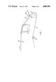
- FIG. 1 is a diagrammatic side view of the downstream portion of a Fourdrinier type papermaking machine incorporating a stationary couch device according to a preferred embodiment of the present invention
- FIG. 2 is a partly cut away view on a larger scale of the couch device of FIG. 1.
- FIG. 3 is a view taken on the line III--III in Figure 2;
- FIG. 4 is a section on IV--IV in FIG. 3;
- FIG. 5 is a section on V--V in FIG. 3;
- FIG. 6 is a section on VI--VI in FIG. 3.
- FIG. 7 is a section on VII--VII in FIG. 3.
- FIG. 1 shows a web 10 carrying the furnish 12 from the upstream parts of a Fourdrinier papermaking machine (not shown) past a stationary couch device 14 according to the present invention.
- the web 10 returns to the upstream end of the machine via a main drive roll 16 and a number of other rolls, of which only the roll 18 is shown.
- the furnish 12 is separated by a conventional pick-up roll 20.
- the web-contacting surface 22 is defined by a curved member 24 of abrasion resistant ceramic material of the type explained above, which member is secured to the steel walls 26 of an otherwise conventional vacuum discharge pump 29. This connection is made by steel members 30 and bolts 32. If desired, the member 24 can also be supported at a location intermediate the walls 26 by an intermediate support (not shown) connected to the vacuum box 28.
- the member 24 is made of a solid material which is continuous from the web-contacting surface 22, which is a first major surface of member 24, to an opposite second major surface 21 of member 24 which is in communication with the vacuum box 28.
- the member 24 is formed with one slot 34 that extends in the direction B, i.e. transversely across the member in relation to the direction A of web travel, and a series of slots 36 that extend obliquely to both directions.
- the member 24 will extend across the entire width of the machine (which in a typical machine could be about 285 inches), while its dimension in the travel direction A could conveniently be of the order of 18 inches.
- FIG. 3 shows only a small portion of one end of the member 24.
- the member 24 will normally be cast as a series of separate pieces that are assembled and accurately aligned with each other in the machine, such alignment being maintained by the bolts 32 and steel members 30 which extend for the full width of the machine.
- the member 24 can be divided into separate pieces along any lines found most convenient, it is believed that division lines that extend parallel to and between a pair of slots 36 (e.g. as designated by the broken line 37) will present the least difficulty in achieving accurate alignment of the pieces.
- the two inward edges of the slot 34 at the division line 37 will be joined by a ceramic bridge 35 that curved in the transverse direction (FIG. 7) to facilitate disposal of fines.
- each slot is provided with a sealing deckle 38 that can be adjusted in the longitudinal direction of the slot 34 or 36 to coordinate the effective edge of the vacuum to the actual edge of the furnish carried by the web.
- Each deckle 38 is moved along its respective slot by a control member 40 that can be moved in the direction B by a rod 42 that is connected to a conventional deckle adjustment mechanism (not shown).
- a conventional deckle adjustment mechanism (not shown).
- some longitudinal movement in the direction A must accompany the oblique movement along the slot. This is enabled by a sliding connection between the deckel 38 and the control member 40, i.e. a downward extension 39 of the deckel 38 that slides in a slot 41 in the member 40.
- FIG. 4 also shows the preferred cross-sectional shape of each slot 36 (slot 34 being similar), namely with relatively sharply inwardly slanting upper portions 43 and 44 that respectively extend into less sloping portions 45 and 46.
- This shape provides a doctoring blade effect at the acute angle edge 47 and a diverging lower area 48 that is useful for disposal of the fines that will be sucked through the web by the vacuum and tend to plug up the slots if not afforded ample space to travel down into the vacuum box 28.
- each slot 36 is provided with a water spray that extends along its length (in a slightly downward direction to minimise rewetting of the furnish carried by the web) from a nozzle 50 situated at the end of a hole 52 extending through the member 24 from a transversely extending header 54 located near the downstream edge of the member 24 in a groove 55 that is itself kept clean by water sprays from a pipe 56.
- Similar water sprays from a pipe 57 serve to dislodge fines collected from the leading edge 58 of the member 24.
- Troughs or "savealls" 59, 60 serve to collect the water and fines falling from these areas.
- the double arrow C designates the vacuum surface, i.e. the effective working surface of the member 24.
- the area of this surface is greater than in a conventional couch roll, which results in improved dewatering.
- a high vacuum e.g. as high as 24" of mercury, can be applied through all parts of all the slots.
- the transverse slots 34 can be dispensed with, if dimpling (i.e. a tendency for the web to be sucked into a slot in a line across the machine) is encountered. This tendency may depend on factors such as the dimensions of the machine parts and the speed of operation of the machine. What is important is that the majority of the slots extend obliquely.
- the oblique slots are illustrated as extending at 45° to the transverse direction, but this angle is not critical, and can be varied for convenience of manufacture. The advantage of arranging the majority of the slots obliquely is a reduction of dimpling, while nevertheless maintaining the doctoring effect afforded by the acute angle edges 47.
- the width of each slot can also increase to maintain the dewatering efficiency of the machine.
- a further important advantage of using a stationary couch device is the avoidance of rewetting of the web and furnish due to the centrifugal throw off of water that occurs with a rotating couch roll, especially one rotating at high speed.
Landscapes
- Paper (AREA)
Applications Claiming Priority (2)
| Application Number | Priority Date | Filing Date | Title |
|---|---|---|---|
| CA511990 | 1986-06-19 | ||
| CA000511990A CA1285411C (fr) | 1986-06-19 | 1986-06-19 | Dispositif coucheur fixe sur machine a papier |
Related Parent Applications (1)
| Application Number | Title | Priority Date | Filing Date |
|---|---|---|---|
| US07060158 Continuation | 1987-06-10 |
Publications (1)
| Publication Number | Publication Date |
|---|---|
| US4880500A true US4880500A (en) | 1989-11-14 |
Family
ID=4133385
Family Applications (1)
| Application Number | Title | Priority Date | Filing Date |
|---|---|---|---|
| US07/236,304 Expired - Fee Related US4880500A (en) | 1986-06-19 | 1988-08-24 | Stationary ceramic couch device with water spray cleaning nozzles |
Country Status (5)
| Country | Link |
|---|---|
| US (1) | US4880500A (fr) |
| EP (1) | EP0253508B1 (fr) |
| BR (1) | BR8703063A (fr) |
| CA (1) | CA1285411C (fr) |
| DE (1) | DE3775643D1 (fr) |
Cited By (11)
| Publication number | Priority date | Publication date | Assignee | Title |
|---|---|---|---|---|
| US5034100A (en) * | 1990-11-28 | 1991-07-23 | Wilbanks International | Stationary drainage device with pressure roll |
| US5076894A (en) * | 1990-05-04 | 1991-12-31 | Simmons Holt W | Suction box apparatus with composite cover elements mounted in slots on cross braces |
| US5328569A (en) * | 1992-06-26 | 1994-07-12 | Beloit Technologies, Inc. | Curved suction box apparatus in a papermaking machine press section |
| US5354426A (en) * | 1993-03-29 | 1994-10-11 | Boise Cascade Corporation | Apparatus and method for removing debris from forming wire |
| US6126788A (en) * | 1997-06-30 | 2000-10-03 | Schiel; Christian | Apparatus for dewatering of paper machine felts |
| DE10116867A1 (de) * | 2001-04-04 | 2002-10-10 | Voith Paper Patent Gmbh | Blattbildungsvorrichtung zum Bilden einer Faserstoffbahn |
| EP1247894A3 (fr) * | 2001-04-02 | 2003-01-02 | Voith Paper Patent GmbH | Presse et caisse d'aspiration |
| DE10247048A1 (de) * | 2002-10-09 | 2004-04-22 | Voith Paper Patent Gmbh | Blattbildungsvorrichtung zum Bilden einer Faserstoffbahn |
| US20040118543A1 (en) * | 2002-12-19 | 2004-06-24 | Kimberly-Clark Worldwide, Inc. | Vacuum device for paper web making apparatus |
| US20060237157A1 (en) * | 2005-04-20 | 2006-10-26 | Zilker Gregory D | Extended couch nip on cylinder former |
| US20090173467A1 (en) * | 2006-05-19 | 2009-07-09 | Metso Paper, Inc. | Static Dewatering Element for a Web Forming Machine and a Method for Covering a Static Dewatering Element Designed for a Web Forming Machine |
Families Citing this family (2)
| Publication number | Priority date | Publication date | Assignee | Title |
|---|---|---|---|---|
| AT392303B (de) * | 1988-10-06 | 1991-03-11 | Bartelmuss Heinrich Ing | Belag |
| DE102006061958A1 (de) | 2006-12-21 | 2008-06-26 | Voith Patent Gmbh | Nassteil für eine Maschine zur Herstellung von Faserstoffbahnen, insbesondere Papiermaschine zur Herstellung holzfreier Papiere |
Citations (13)
| Publication number | Priority date | Publication date | Assignee | Title |
|---|---|---|---|---|
| US2408176A (en) * | 1943-12-16 | 1946-09-24 | Proulx Jean | Cover for the suction boxes of papermaking machines |
| US2712776A (en) * | 1953-08-13 | 1955-07-12 | Arthur P Wagenknecht | Cover for suction box of paper machines |
| US2728273A (en) * | 1951-12-29 | 1955-12-27 | Black Clawson Co | Paper machinery |
| US2976925A (en) * | 1958-02-03 | 1961-03-28 | Appleton Wood Products Co | Reinforced suction box cover |
| US3022821A (en) * | 1959-01-05 | 1962-02-27 | Henry J Mcardle | Suction box cover |
| US3441476A (en) * | 1965-01-22 | 1969-04-29 | Voith Gmbh J M | Paper web transfer device utilizing suction box |
| DE2131984A1 (de) * | 1970-07-01 | 1972-02-10 | Escher Wyss Gmbh | Nasspartie einer Papiermaschine |
| US3758380A (en) * | 1971-07-06 | 1973-09-11 | Price Co Ltd | Paper machine couching box with a multiperforate surface |
| US3836428A (en) * | 1972-08-25 | 1974-09-17 | Albany Int Corp | Adjustable slot suction box cover |
| US3846233A (en) * | 1972-09-11 | 1974-11-05 | Valmet Oy | Papermaking machine having a single wire run and a double wire run over a downwardly curving dewatering box |
| US4113557A (en) * | 1976-04-14 | 1978-09-12 | Valmet Oy | Paper manufacturing structure particularly for detaching a web from a wire |
| US4285768A (en) * | 1978-06-15 | 1981-08-25 | J. M. Voith Gmbh | Apparatus for dewatering fiber suspension for producing a web of fiber |
| US4484981A (en) * | 1982-07-26 | 1984-11-27 | Feldmuhle Aktiengesellschaft | Papermaking dewatering apparatus having wire support means with cooling water feed means |
Family Cites Families (2)
| Publication number | Priority date | Publication date | Assignee | Title |
|---|---|---|---|---|
| DE1095103B (de) * | 1955-12-27 | 1960-12-15 | Ontario Paper Company Ltd | Saugkasten fuer Langsiebpapiermaschinen |
| DE2552485A1 (de) * | 1975-11-22 | 1977-06-02 | Voith Gmbh J M | Zylindrische fuehrungsvorrichtung fuer faserstoffbahnen |
-
1986
- 1986-06-19 CA CA000511990A patent/CA1285411C/fr not_active Expired - Fee Related
-
1987
- 1987-06-16 DE DE8787305307T patent/DE3775643D1/de not_active Expired - Fee Related
- 1987-06-16 EP EP87305307A patent/EP0253508B1/fr not_active Expired - Lifetime
- 1987-06-18 BR BR8703063A patent/BR8703063A/pt active Search and Examination
-
1988
- 1988-08-24 US US07/236,304 patent/US4880500A/en not_active Expired - Fee Related
Patent Citations (13)
| Publication number | Priority date | Publication date | Assignee | Title |
|---|---|---|---|---|
| US2408176A (en) * | 1943-12-16 | 1946-09-24 | Proulx Jean | Cover for the suction boxes of papermaking machines |
| US2728273A (en) * | 1951-12-29 | 1955-12-27 | Black Clawson Co | Paper machinery |
| US2712776A (en) * | 1953-08-13 | 1955-07-12 | Arthur P Wagenknecht | Cover for suction box of paper machines |
| US2976925A (en) * | 1958-02-03 | 1961-03-28 | Appleton Wood Products Co | Reinforced suction box cover |
| US3022821A (en) * | 1959-01-05 | 1962-02-27 | Henry J Mcardle | Suction box cover |
| US3441476A (en) * | 1965-01-22 | 1969-04-29 | Voith Gmbh J M | Paper web transfer device utilizing suction box |
| DE2131984A1 (de) * | 1970-07-01 | 1972-02-10 | Escher Wyss Gmbh | Nasspartie einer Papiermaschine |
| US3758380A (en) * | 1971-07-06 | 1973-09-11 | Price Co Ltd | Paper machine couching box with a multiperforate surface |
| US3836428A (en) * | 1972-08-25 | 1974-09-17 | Albany Int Corp | Adjustable slot suction box cover |
| US3846233A (en) * | 1972-09-11 | 1974-11-05 | Valmet Oy | Papermaking machine having a single wire run and a double wire run over a downwardly curving dewatering box |
| US4113557A (en) * | 1976-04-14 | 1978-09-12 | Valmet Oy | Paper manufacturing structure particularly for detaching a web from a wire |
| US4285768A (en) * | 1978-06-15 | 1981-08-25 | J. M. Voith Gmbh | Apparatus for dewatering fiber suspension for producing a web of fiber |
| US4484981A (en) * | 1982-07-26 | 1984-11-27 | Feldmuhle Aktiengesellschaft | Papermaking dewatering apparatus having wire support means with cooling water feed means |
Cited By (17)
| Publication number | Priority date | Publication date | Assignee | Title |
|---|---|---|---|---|
| US5076894A (en) * | 1990-05-04 | 1991-12-31 | Simmons Holt W | Suction box apparatus with composite cover elements mounted in slots on cross braces |
| US5034100A (en) * | 1990-11-28 | 1991-07-23 | Wilbanks International | Stationary drainage device with pressure roll |
| US5328569A (en) * | 1992-06-26 | 1994-07-12 | Beloit Technologies, Inc. | Curved suction box apparatus in a papermaking machine press section |
| US5354426A (en) * | 1993-03-29 | 1994-10-11 | Boise Cascade Corporation | Apparatus and method for removing debris from forming wire |
| US6126788A (en) * | 1997-06-30 | 2000-10-03 | Schiel; Christian | Apparatus for dewatering of paper machine felts |
| EP1247894A3 (fr) * | 2001-04-02 | 2003-01-02 | Voith Paper Patent GmbH | Presse et caisse d'aspiration |
| DE10116867A1 (de) * | 2001-04-04 | 2002-10-10 | Voith Paper Patent Gmbh | Blattbildungsvorrichtung zum Bilden einer Faserstoffbahn |
| DE10247048A1 (de) * | 2002-10-09 | 2004-04-22 | Voith Paper Patent Gmbh | Blattbildungsvorrichtung zum Bilden einer Faserstoffbahn |
| US20040118543A1 (en) * | 2002-12-19 | 2004-06-24 | Kimberly-Clark Worldwide, Inc. | Vacuum device for paper web making apparatus |
| WO2004061212A1 (fr) * | 2002-12-19 | 2004-07-22 | Kimberly-Clark Worldwide, Inc. | Appareil a vide pour dispositif de fabrication d'une bande de papier |
| US7001486B2 (en) | 2002-12-19 | 2006-02-21 | Kimberly-Clark Worldwide, Inc. | Vacuum device for paper web making apparatus |
| AU2003251947B2 (en) * | 2002-12-19 | 2009-01-08 | Kimberly-Clark Worldwide, Inc. | Vacuum device for paper web making apparatus |
| US20060237157A1 (en) * | 2005-04-20 | 2006-10-26 | Zilker Gregory D | Extended couch nip on cylinder former |
| WO2006115796A1 (fr) | 2005-04-20 | 2006-11-02 | Albany International Corp. | Pinceur coucheur étendu sur formeur cylindrique |
| US7510630B2 (en) | 2005-04-20 | 2009-03-31 | Albany International Corp. | Extended couch nip on cylinder former |
| US20090173467A1 (en) * | 2006-05-19 | 2009-07-09 | Metso Paper, Inc. | Static Dewatering Element for a Web Forming Machine and a Method for Covering a Static Dewatering Element Designed for a Web Forming Machine |
| US8070915B2 (en) * | 2006-05-19 | 2011-12-06 | Metso Paper, Inc. | Static dewatering element for a web forming machine and a method for covering a static dewatering element designed for a web forming machine |
Also Published As
| Publication number | Publication date |
|---|---|
| DE3775643D1 (de) | 1992-02-13 |
| EP0253508B1 (fr) | 1992-01-02 |
| CA1285411C (fr) | 1991-07-02 |
| EP0253508A2 (fr) | 1988-01-20 |
| EP0253508A3 (en) | 1988-09-07 |
| BR8703063A (pt) | 1988-03-08 |
Similar Documents
| Publication | Publication Date | Title |
|---|---|---|
| US4880500A (en) | Stationary ceramic couch device with water spray cleaning nozzles | |
| US3726758A (en) | Twin-wire web forming system with dewatering by centrifugal forces | |
| US5381580A (en) | Device for cleaning a paper machine wire web | |
| US3438854A (en) | Dual wire paper forming apparatus and suction box therefor | |
| US3309263A (en) | Web pickup and transfer for a papermaking machine | |
| US4557802A (en) | Apparatus for affecting a web drained on a wire | |
| US4420370A (en) | Pulp agitating device and method having multiple protruding inserts | |
| US5034100A (en) | Stationary drainage device with pressure roll | |
| US3691010A (en) | Method and apparatus for dewatering paper webs | |
| US4123322A (en) | Drainage foil element having two wire bearing portions | |
| FI77281C (fi) | Hybridformare foer en pappersmaskin. | |
| EP0267186A1 (fr) | Presse servant a presser une bande en mouvement. | |
| EP0369611A2 (fr) | Appareil pour épaissir des suspensions de pâte à papier | |
| FI91788C (fi) | Paperikoneen kaksiviirainen rainanmuodostusosa | |
| US3992253A (en) | Papermaking machine having a suction zone free of wire supports | |
| EP0615565B1 (fr) | Appareil d'injection a jet regule pour une caisse de tete d'une machine de fabrication de papier | |
| KR850000480B1 (ko) | 쌍 와이어 성형 장치 | |
| US7005040B2 (en) | Fabric support element for a papermaking machine | |
| US4560438A (en) | Method and apparatus for reducing the energy consumed when drying a paper web | |
| JPH11514710A (ja) | ウエブフォーマにおけるウエブの再湿潤防止方法および装置 | |
| US7491295B2 (en) | Dewatering element having non-pulsing dewatering followed by pulsing dewatering | |
| US2503436A (en) | Suction box | |
| US3637460A (en) | Dewatering apparatus | |
| US5724749A (en) | Siphon for removing condensate from a planar band | |
| CA2158728A1 (fr) | Transport sans traction d'une bande dans une section de compression |
Legal Events
| Date | Code | Title | Description |
|---|---|---|---|
| FPAY | Fee payment |
Year of fee payment: 4 |
|
| REMI | Maintenance fee reminder mailed | ||
| LAPS | Lapse for failure to pay maintenance fees | ||
| FP | Expired due to failure to pay maintenance fee |
Effective date: 19971119 |
|
| STCH | Information on status: patent discontinuation |
Free format text: PATENT EXPIRED DUE TO NONPAYMENT OF MAINTENANCE FEES UNDER 37 CFR 1.362 |