US4881585A - Bench type milling cutter - Google Patents
Bench type milling cutter Download PDFInfo
- Publication number
- US4881585A US4881585A US07/263,263 US26326388A US4881585A US 4881585 A US4881585 A US 4881585A US 26326388 A US26326388 A US 26326388A US 4881585 A US4881585 A US 4881585A
- Authority
- US
- United States
- Prior art keywords
- carrier
- slide
- bearing
- leg
- rotation
- Prior art date
- Legal status (The legal status is an assumption and is not a legal conclusion. Google has not performed a legal analysis and makes no representation as to the accuracy of the status listed.)
- Expired - Fee Related
Links
Images
Classifications
-
- B—PERFORMING OPERATIONS; TRANSPORTING
- B27—WORKING OR PRESERVING WOOD OR SIMILAR MATERIAL; NAILING OR STAPLING MACHINES IN GENERAL
- B27C—PLANING, DRILLING, MILLING, TURNING OR UNIVERSAL MACHINES FOR WOOD OR SIMILAR MATERIAL
- B27C5/00—Machines designed for producing special profiles or shaped work, e.g. by rotary cutters; Equipment therefor
- B27C5/02—Machines with table
-
- Y—GENERAL TAGGING OF NEW TECHNOLOGICAL DEVELOPMENTS; GENERAL TAGGING OF CROSS-SECTIONAL TECHNOLOGIES SPANNING OVER SEVERAL SECTIONS OF THE IPC; TECHNICAL SUBJECTS COVERED BY FORMER USPC CROSS-REFERENCE ART COLLECTIONS [XRACs] AND DIGESTS
- Y10—TECHNICAL SUBJECTS COVERED BY FORMER USPC
- Y10T—TECHNICAL SUBJECTS COVERED BY FORMER US CLASSIFICATION
- Y10T409/00—Gear cutting, milling, or planing
- Y10T409/30—Milling
- Y10T409/30784—Milling including means to adustably position cutter
- Y10T409/307952—Linear adjustment
- Y10T409/308232—Linear adjustment and angular adjustment
-
- Y—GENERAL TAGGING OF NEW TECHNOLOGICAL DEVELOPMENTS; GENERAL TAGGING OF CROSS-SECTIONAL TECHNOLOGIES SPANNING OVER SEVERAL SECTIONS OF THE IPC; TECHNICAL SUBJECTS COVERED BY FORMER USPC CROSS-REFERENCE ART COLLECTIONS [XRACs] AND DIGESTS
- Y10—TECHNICAL SUBJECTS COVERED BY FORMER USPC
- Y10T—TECHNICAL SUBJECTS COVERED BY FORMER US CLASSIFICATION
- Y10T409/00—Gear cutting, milling, or planing
- Y10T409/30—Milling
- Y10T409/309184—Milling including cutter limited to rotary motion
Definitions
- the invention concerns a bench type cutter of the type in which a cutting tool is mounted on a work bench.
- the tool is affixed to a tool axle, the ends of which are rotatably held in upper and lower legs, respectively, of a bearing assembly.
- a connector portion of the bearing assembly interconnects the legs and passes through a passage in the work bench.
- a bench type milling cutter of this type is known from DE-OS 33 37 265 in which a milling cutter is attached to a vertical axle, the axle being rotatably mounted in upper and lower bearings.
- the lower bearing is mounted on a lower bearing holder carried by the lower horizontal leg of a U-shaped bearing block.
- the upper bearing is attached to an upper horizontal leg of the bearing block.
- the bearing block is attached pivotably to a base, the latter being affixed to the underside of a horizontal workbench table.
- the bearing block is thus rotatably about a horizontal axis to enable the inclination of the axle to be varied.
- This object is attained in the case of a bench type milling cutter of the afore-mentioned type wherein a bearing block assembly is carried by a carrier and is linearly vertically adjustable relative to the carrier by means of a manual actuator.
- the carrier in turn, is mounted on a base for rotation relative to the base within a vertical plane containing the tool axis, such rotation created by a manual actuator.
- the base comprises a slide which is movable horizontally relative to the work bench so that the tool may be displaced horizontally in relation to the workpiece so that processing that is not possible with the known bench type milling tools, may be carried out without reclamping the workpiece.
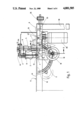
- FIG. 1 is a schematic lateral elevational view of a bench type milling cutter according to the invention
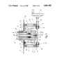
- FIG. 2 is a vertical section through the bench type milling cutter taken along the line II--II of FIG. 1, with parts of the assembly broken away;
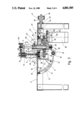
- FIG. 3 is a vertical sectional view through the milling cutter taken along the line III--III of FIG. 2;
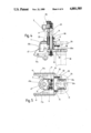
- FIG. 4 is a vertical sectional view through a portion of the apparatus including the bearing assembly and carrier;
- FIG. 5 is a plan view of the sliding piece of FIG. 4.
- the novel bench type milling cutter comprises a work bench (6), a horizontal work table (6A) of which is supported in a known manner by means of column legs on the ground.
- the table is able to support a workpiece (not shown).
- Mounted to the work bench is a tool-carrying module comprising a base or slide (10), a carrier (17), and a bearing assembly (3, 4, 14, 15) as will be explained hereinafter.
- the slide (10) is located adjacent the underside of the table and is horizontally linearly displaceable in a direction parallel to the plane of the table (6A).
- the slide includes a guide plate (37) and downwardly depending jaws (12) arranged parallel to each other.
- the slide (10) constructed in this manner is held displaceably on the bottom side of the table (6A) by screws (38) mounted in the table (6A).
- the screws project through guide slots (27) in the plate (37), thereby enabling the plate (37) to be displaceable relative to the bench (6) in the direction of the guide slots (27).
- a clamping plate (39) is pressed against the plate (37) by nuts to hold the plate (37) in adjusted positions.
- the guide plate (37) is provided on one end with a rim (40) on which an adjusting spindle (25) is fixedly mounted with its axle parallel to the plate (37).
- This adjusting spindle (25) is received threadedly in an adjusting nut (26), which is supported rotatingly on an outer edge of the work bench (6) and is equipped with knurling (41) for manual actuation.
- the afore-mentioned linear displacement of the slide (10) may therefore be effected by rotating the adjusting nut (26).
- a sliding piece or carrier (17) is movably guided.
- the carrier (17) has two legs (42) abutting tightly against the jaws (12) of the slide (10).
- Outwardly directed curved projections (43) of the carrier engage guide slots (11) formed in the inner side of the jaws (12).
- Each guide slot (11) has the configuration of a circular arc as depicted in FIG. 3.
- the center of curvature (13) of the slots (11) defines a pivot axis for the carrier (17), which axis preferably lies on the surface of the table (6A).
- Rods (14, 15) are slidably guided without radial clearance in the sleeves.
- the lower ends of the rods (15) are fixedly connected to a yoke-like body forming part of a lower leg or head (4) of the bearing assembly, as described in more detail below.
- the upper ends of the rods (14 and 15) are fixedly connected with an upper leg or head (3) which has the configuration of a yoke.
- the rods (14, 15) pass through a passage (35) in the table (6A).
- the lower bearing head (4) carries a lower bearing (44A) which holds a milling spindle (28).
- the spindle is drawn upwardly by a threaded bolt (45).
- the bolt (45) also presses an axially displaceable stub shaft (44) tightly against the milling tool (2) and presses the latter simultaneously against a suitable cone (46) of the milling spindle (28), to entrain the tool for rotation with the spindle.
- the stub shaft (44) is held in a suitable bearing (44B) in the upper leg (3).
- the bolt (45), spindle (28), and stub shaft (44) form a tool axle assemble which is driven about an axis (8) by a drive mechanism.
- the lower bearing head (4) is extended downwards in the manner of a skirt and has lateral walls (47) surrounding a belt pulley (48) fixedly connected with the spindle (28) and a drive belt (29) slung around the pulley (48).
- the drive belt (29) passes through downwardly open slots (49) in the carrier (17) and is looped around an output shaft (50) of a drive motor (30).
- the drive motor (30) has a bearing collar (30a) held in a recess (31) of an arm (32) of the lower leg.
- the arm extends rigidly from a connecting piece (51) of the bearing head (4) in a direction facing away from the belt pulley (48).
- the arm (32) may comprise two clamping pieces, with one part (31a) thereof (FIG. 5) fixedly connected with the part (51), while the other part (31b) may be screwed to the part (31a).
- the two parts together form a recess (31) in which the motor may be clamped.
- the arm (32) is additionally provided with a tensioner (33) to adjust the tension of the belt.
- Support screws (52) are held on the part (31a) of the arm (32) and have heads pressing against upper end (53) of the output shaft of the drive motor (30).
- a support plate (54) is fixed to that output shaft and abuts against the underside of the plate (37).
- the tension of the belt (29) may be adjusted by means of the screws (52).
- the part (31b) is thereafter fastened.
- the bearing heads (3 and 4) as interconnected by the rods (14, 15) form a generally U-shaped bearing block or bearing assembly, with the heads (3 and 4) forming generally parallel legs of the U-shape.
- the columns (14 and 15) are adjustably displaceable upwards and downwards in the sleeve (16) of the carrier (17) and are adjustably held at adjusted locations therein by locking screws (56).
- An adjusting bolt (9) is connected in an axially stationary manner with the upper bearing head (3).
- the bolt (9) is connected fixedly in rotation with a manually actuable adjusting wheel (55) and is threadedly connected at (22) to one of the sleeves (16) of the carrier (17).
- the adjusting bolt (9) By rotating the adjusting bolt (9), which may be carried out simply by actuating the manual wheel (55), the bearing block may be displaced vertically, relative to the carrier (17), along with the columns (14 and 15) which slide in the guide sleeves (16), after the corresponding locking screws (56) are loosened.
- the height of the milling tool may be adjusted relative to the work bench (6) in a simple manner.
- the slide (10) and tool (2) may also be adjusted in a direction parallel to the table (6A).
- An adjusting shaft (18) is supported rotatably in ears (57) of the legs (42) of the carrier (17).
- the shaft (18) is connected fixedly at one end with a manually actuable wheel (19).
- An opposite end of the shaft (18) carries a toothed pinion (20), the pinion engaging a circular arch shaped toothing (21) on the outer edge of one of the jaws (12).
- the manual wheel (19) is located far enough to the outside, so that it projects past the lateral edges of the work bench (6) for convenient access. If the inclination of the tool axis (8) is to be set, the carrier (17) is pivoted between the jaws (12) of the slide (10) by the actuation of the manual wheel (19).
- the carrier (17) slides around the pivot axle (13), until for example, the stub shaft (44) reaches a terminal position (44') indicated in FIGS. 1, 3.
- the milling axis (8) then occupies the position (8') (FIG. 3), in which it forms an angle of approximately 25° with the table (6A) of the bench (6).
- the passage (35) in the table (6A) is large enough so that this pivot position can be attained.
- the configuration of the carrier (17) is such as to make possible the attainment of this extreme pivoted position.
- a side (47a) of the walls (47) is flattened.
- the location of the motor (30) remotely of the table provides the advantage that the relatively bulky motor does not impede the pivoting motion by striking parts of the table.
- a compression spring (23) is placed around the adjusting bolt (9), which ensures that the upper bearing head (3) is always biased upwards, away from the table (6A). The distance of the bearing head (3) from the upper edge of the sleeve (16) can therefore be adjusted only by actuating the adjusting spindle (9).
- a feeler member (34) is mounted on the upper leg (3) and is adjustable by a threaded knob (34A) in a direction which is radial relative to the axis (8).
- the feeler member is adapted to contact a guide plate (not shown) which cams the tool for a copying action in a conventional manner.
- the members (3, 4, 14, 15), form a bearing block assembly which is carried by the carrier (17) and which is vertically adjustable relative to the carrier (17) by means of the knob (55).
- the carrier (17) in turn, is mounted on the slide (10) for rotation relative to the guide within a vertical plane containing the tool axis (8), such rotation created by turning of knob (19).
- the slide (10) is horizontally slidable relative to the work bench in response to rotation of the knob (41).
Landscapes
- Life Sciences & Earth Sciences (AREA)
- Engineering & Computer Science (AREA)
- Mechanical Engineering (AREA)
- Wood Science & Technology (AREA)
- Forests & Forestry (AREA)
- Machine Tool Units (AREA)
- Milling, Drilling, And Turning Of Wood (AREA)
- Milling Processes (AREA)
Applications Claiming Priority (2)
| Application Number | Priority Date | Filing Date | Title |
|---|---|---|---|
| DE3736757 | 1987-10-30 | ||
| DE3736757A DE3736757C1 (de) | 1987-10-30 | 1987-10-30 | Tischfraeseinrichtung |
Publications (1)
| Publication Number | Publication Date |
|---|---|
| US4881585A true US4881585A (en) | 1989-11-21 |
Family
ID=6339392
Family Applications (1)
| Application Number | Title | Priority Date | Filing Date |
|---|---|---|---|
| US07/263,263 Expired - Fee Related US4881585A (en) | 1987-10-30 | 1988-10-27 | Bench type milling cutter |
Country Status (4)
| Country | Link |
|---|---|
| US (1) | US4881585A (fr) |
| EP (1) | EP0314029B1 (fr) |
| JP (1) | JPH01146607A (fr) |
| DE (2) | DE3736757C1 (fr) |
Cited By (5)
| Publication number | Priority date | Publication date | Assignee | Title |
|---|---|---|---|---|
| US5611378A (en) * | 1996-01-19 | 1997-03-18 | Ryobi North America | Tilting router table |
| US5819395A (en) * | 1996-08-29 | 1998-10-13 | Western Atlas, Inc. | Machine tool module with cutting tool and superimposed workpiece-carrying platen |
| US20070197345A1 (en) * | 2006-02-13 | 2007-08-23 | Wallace Gregory A | Motivational displays and methods for exercise machine |
| CN101791810A (zh) * | 2010-03-31 | 2010-08-04 | 深圳华中数控有限公司 | 极坐标数控木工篓铣机 |
| WO2024127337A1 (fr) * | 2022-12-16 | 2024-06-20 | Henk Van Oeveren | Machine à moulurer à arbre et procédé associé |
Families Citing this family (7)
| Publication number | Priority date | Publication date | Assignee | Title |
|---|---|---|---|---|
| JP3626385B2 (ja) * | 2000-01-20 | 2005-03-09 | 株式会社東芝 | アンテナ装置 |
| DE10013571A1 (de) * | 2000-03-18 | 2001-09-27 | Leonhard Hofmann Maschinenfabr | Schwenkfräsmaschine |
| JP4836349B2 (ja) * | 2001-04-23 | 2011-12-14 | 住友重機械工業株式会社 | 2段形ウォーム減速機のシリーズ |
| ITBO20040335A1 (it) * | 2004-05-25 | 2004-08-25 | Scm Group Spa | Macchina per la lavorazione di pannelli in legno o assimilabili |
| DE202013008050U1 (de) | 2013-09-12 | 2013-10-25 | Peter Schmid | Stationäre Fräsvorrichtung |
| CN104890089B (zh) * | 2015-06-19 | 2017-03-01 | 李青祝 | 木地板钝刀加工装置 |
| CN116372689B (zh) * | 2023-06-02 | 2023-08-11 | 新乡亿威数控机床有限公司 | 一种大型卧式轴承环外圆加工用磨床 |
Citations (7)
| Publication number | Priority date | Publication date | Assignee | Title |
|---|---|---|---|---|
| US1275215A (en) * | 1917-05-10 | 1918-08-13 | Wendell R Buss | Motor-drive for shapers. |
| US1335547A (en) * | 1919-01-13 | 1920-03-30 | Lemuel A Bartholomew | Woodworking-machine |
| US2353202A (en) * | 1941-06-10 | 1944-07-11 | Delta Mfg Co | Shaper |
| US2744550A (en) * | 1952-02-12 | 1956-05-08 | Reamstown Products Company | Multiple position woodworking machine |
| US3008501A (en) * | 1958-05-21 | 1961-11-14 | Hammer Waldemar | Multiple vertical spindle woodworking machine and method of woodworking |
| US3710833A (en) * | 1950-03-14 | 1973-01-16 | I Hammer | Power driven shaper apparatus |
| DE3337261A1 (de) * | 1983-10-13 | 1985-05-02 | Atlas Fahrzeugtechnik GmbH, 5980 Werdohl | Vergaser fuer einen ottomotor |
Family Cites Families (4)
| Publication number | Priority date | Publication date | Assignee | Title |
|---|---|---|---|---|
| DE493004C (de) * | 1925-04-09 | 1930-03-03 | Ernst Rueger | Elektromotorisch angetriebene Holzbearbeitungsmaschine |
| US3454061A (en) * | 1966-12-22 | 1969-07-08 | Rockwell Mfg Co | Power tool |
| CH586098A5 (fr) * | 1974-09-25 | 1977-03-31 | Oertli Werkzeuge Ag | |
| DE8329576U1 (de) * | 1983-10-13 | 1986-03-06 | Eugen Lutz GmbH u. Co Maschinenfabrik, 7130 Mühlacker | Fräsvorrichtung mit einer Hand-Oberfräse |
-
1987
- 1987-10-30 DE DE3736757A patent/DE3736757C1/de not_active Expired
-
1988
- 1988-10-22 EP EP88117639A patent/EP0314029B1/fr not_active Expired - Lifetime
- 1988-10-22 DE DE88117639T patent/DE3883141T2/de not_active Expired - Fee Related
- 1988-10-27 US US07/263,263 patent/US4881585A/en not_active Expired - Fee Related
- 1988-10-28 JP JP63271124A patent/JPH01146607A/ja active Pending
Patent Citations (7)
| Publication number | Priority date | Publication date | Assignee | Title |
|---|---|---|---|---|
| US1275215A (en) * | 1917-05-10 | 1918-08-13 | Wendell R Buss | Motor-drive for shapers. |
| US1335547A (en) * | 1919-01-13 | 1920-03-30 | Lemuel A Bartholomew | Woodworking-machine |
| US2353202A (en) * | 1941-06-10 | 1944-07-11 | Delta Mfg Co | Shaper |
| US3710833A (en) * | 1950-03-14 | 1973-01-16 | I Hammer | Power driven shaper apparatus |
| US2744550A (en) * | 1952-02-12 | 1956-05-08 | Reamstown Products Company | Multiple position woodworking machine |
| US3008501A (en) * | 1958-05-21 | 1961-11-14 | Hammer Waldemar | Multiple vertical spindle woodworking machine and method of woodworking |
| DE3337261A1 (de) * | 1983-10-13 | 1985-05-02 | Atlas Fahrzeugtechnik GmbH, 5980 Werdohl | Vergaser fuer einen ottomotor |
Cited By (6)
| Publication number | Priority date | Publication date | Assignee | Title |
|---|---|---|---|---|
| US5611378A (en) * | 1996-01-19 | 1997-03-18 | Ryobi North America | Tilting router table |
| US5819395A (en) * | 1996-08-29 | 1998-10-13 | Western Atlas, Inc. | Machine tool module with cutting tool and superimposed workpiece-carrying platen |
| US20070197345A1 (en) * | 2006-02-13 | 2007-08-23 | Wallace Gregory A | Motivational displays and methods for exercise machine |
| CN101791810A (zh) * | 2010-03-31 | 2010-08-04 | 深圳华中数控有限公司 | 极坐标数控木工篓铣机 |
| CN101791810B (zh) * | 2010-03-31 | 2012-06-13 | 深圳华中数控有限公司 | 极坐标数控木工篓铣机 |
| WO2024127337A1 (fr) * | 2022-12-16 | 2024-06-20 | Henk Van Oeveren | Machine à moulurer à arbre et procédé associé |
Also Published As
| Publication number | Publication date |
|---|---|
| DE3883141T2 (de) | 1993-12-23 |
| EP0314029A2 (fr) | 1989-05-03 |
| EP0314029A3 (en) | 1990-12-05 |
| DE3736757C1 (de) | 1989-05-18 |
| DE3883141D1 (de) | 1993-09-16 |
| EP0314029B1 (fr) | 1993-08-11 |
| JPH01146607A (ja) | 1989-06-08 |
Similar Documents
| Publication | Publication Date | Title |
|---|---|---|
| US4445811A (en) | Setting mechanisms especially for tools for carrying out routing and like operations | |
| US4881585A (en) | Bench type milling cutter | |
| US4537234A (en) | Routing machines | |
| KR101411068B1 (ko) | 공작물 너얼링 절삭 가공 장치 | |
| US2973576A (en) | Electric cutting machine | |
| US3952616A (en) | Adjustable grinding apparatus | |
| GB2286150A (en) | Circular hand saw with swing protective hood and with a depth-of-cut adjusting device. | |
| US2619135A (en) | Multiple machine tool | |
| US3011533A (en) | Combination power tool with adjustable tool spindle | |
| US4669348A (en) | Machine saw | |
| GB1325650A (en) | Machine tool | |
| JPH0729275B2 (ja) | シート材料裁断機械 | |
| US5738572A (en) | Grinding machine | |
| US4524544A (en) | Machine for backing-off and/or grinding drifting spindles provided with teeth | |
| DE3161060D1 (en) | Edge grinding machine for plate-shaped workpieces, particularly plates of glass or stone | |
| US4528881A (en) | Biased power feed device having means to reduce bias during adjustment | |
| US4144676A (en) | Machine tool having frame mounted head and tail stocks | |
| GB1495202A (en) | Grinding machine | |
| CN220051363U (zh) | 数控磨床的自动刀架 | |
| US3747278A (en) | Tool and workpiece holder | |
| US4228710A (en) | Cut-off saw attachment for machine tool | |
| US504006A (en) | vogel | |
| US3165977A (en) | Machine tool with an angularly adjustable spindle head | |
| JP2509450B2 (ja) | レ―ル頭部溶接残部の研削装置 | |
| RU2083350C1 (ru) | Устройство астапова н.а. для ручной заточки строгальных резцов |
Legal Events
| Date | Code | Title | Description |
|---|---|---|---|
| AS | Assignment |
Owner name: BLACK & DECKER OVERSEAS AG, VADUZ, LIECHTENSTEIN, Free format text: ASSIGNMENT OF ASSIGNORS INTEREST.;ASSIGNOR:BERGLER, OTTO;REEL/FRAME:004975/0316 Effective date: 19881020 Owner name: BLACK & DECKER OVERSEAS AG, A CORP. OF LIECHTENST Free format text: ASSIGNMENT OF ASSIGNORS INTEREST;ASSIGNOR:BERGLER, OTTO;REEL/FRAME:004975/0316 Effective date: 19881020 |
|
| FEPP | Fee payment procedure |
Free format text: PAYOR NUMBER ASSIGNED (ORIGINAL EVENT CODE: ASPN); ENTITY STATUS OF PATENT OWNER: LARGE ENTITY |
|
| FEPP | Fee payment procedure |
Free format text: PAYOR NUMBER ASSIGNED (ORIGINAL EVENT CODE: ASPN); ENTITY STATUS OF PATENT OWNER: LARGE ENTITY Free format text: PAYER NUMBER DE-ASSIGNED (ORIGINAL EVENT CODE: RMPN); ENTITY STATUS OF PATENT OWNER: LARGE ENTITY |
|
| FPAY | Fee payment |
Year of fee payment: 4 |
|
| REMI | Maintenance fee reminder mailed | ||
| LAPS | Lapse for failure to pay maintenance fees | ||
| FP | Lapsed due to failure to pay maintenance fee |
Effective date: 19971126 |
|
| STCH | Information on status: patent discontinuation |
Free format text: PATENT EXPIRED DUE TO NONPAYMENT OF MAINTENANCE FEES UNDER 37 CFR 1.362 |