US4881842A - Wheel bearing assembly - Google Patents
Wheel bearing assembly Download PDFInfo
- Publication number
- US4881842A US4881842A US07/259,020 US25902088A US4881842A US 4881842 A US4881842 A US 4881842A US 25902088 A US25902088 A US 25902088A US 4881842 A US4881842 A US 4881842A
- Authority
- US
- United States
- Prior art keywords
- stub shaft
- bearing member
- hollow spindle
- snap ring
- inner bearing
- Prior art date
- Legal status (The legal status is an assumption and is not a legal conclusion. Google has not performed a legal analysis and makes no representation as to the accuracy of the status listed.)
- Expired - Fee Related
Links
- 230000000712 assembly Effects 0.000 description 2
- 238000000429 assembly Methods 0.000 description 2
- 230000000717 retained effect Effects 0.000 description 2
- 238000010276 construction Methods 0.000 description 1
- 238000012986 modification Methods 0.000 description 1
- 230000004048 modification Effects 0.000 description 1
Images


Classifications
-
- B—PERFORMING OPERATIONS; TRANSPORTING
- B60—VEHICLES IN GENERAL
- B60B—VEHICLE WHEELS; CASTORS; AXLES FOR WHEELS OR CASTORS; INCREASING WHEEL ADHESION
- B60B27/00—Hubs
- B60B27/0005—Hubs with ball bearings
-
- F—MECHANICAL ENGINEERING; LIGHTING; HEATING; WEAPONS; BLASTING
- F16—ENGINEERING ELEMENTS AND UNITS; GENERAL MEASURES FOR PRODUCING AND MAINTAINING EFFECTIVE FUNCTIONING OF MACHINES OR INSTALLATIONS; THERMAL INSULATION IN GENERAL
- F16C—SHAFTS; FLEXIBLE SHAFTS; ELEMENTS OR CRANKSHAFT MECHANISMS; ROTARY BODIES OTHER THAN GEARING ELEMENTS; BEARINGS
- F16C35/00—Rigid support of bearing units; Housings, e.g. caps, covers
- F16C35/04—Rigid support of bearing units; Housings, e.g. caps, covers in the case of ball or roller bearings
- F16C35/06—Mounting or dismounting of ball or roller bearings; Fixing them onto shaft or in housing
- F16C35/063—Fixing them on the shaft
- F16C35/0635—Fixing them on the shaft the bore of the inner ring being of special non-cylindrical shape which co-operates with a complementary shape on the shaft, e.g. teeth, polygonal sections
-
- F—MECHANICAL ENGINEERING; LIGHTING; HEATING; WEAPONS; BLASTING
- F16—ENGINEERING ELEMENTS AND UNITS; GENERAL MEASURES FOR PRODUCING AND MAINTAINING EFFECTIVE FUNCTIONING OF MACHINES OR INSTALLATIONS; THERMAL INSULATION IN GENERAL
- F16D—COUPLINGS FOR TRANSMITTING ROTATION; CLUTCHES; BRAKES
- F16D1/00—Couplings for rigidly connecting two coaxial shafts or other movable machine elements
- F16D1/10—Quick-acting couplings in which the parts are connected by simply bringing them together axially
- F16D1/108—Quick-acting couplings in which the parts are connected by simply bringing them together axially having retaining means rotating with the coupling and acting by interengaging parts, i.e. positive coupling
- F16D1/116—Quick-acting couplings in which the parts are connected by simply bringing them together axially having retaining means rotating with the coupling and acting by interengaging parts, i.e. positive coupling the interengaging parts including a continuous or interrupted circumferential groove in the surface of one of the coupling parts
-
- F—MECHANICAL ENGINEERING; LIGHTING; HEATING; WEAPONS; BLASTING
- F16—ENGINEERING ELEMENTS AND UNITS; GENERAL MEASURES FOR PRODUCING AND MAINTAINING EFFECTIVE FUNCTIONING OF MACHINES OR INSTALLATIONS; THERMAL INSULATION IN GENERAL
- F16B—DEVICES FOR FASTENING OR SECURING CONSTRUCTIONAL ELEMENTS OR MACHINE PARTS TOGETHER, e.g. NAILS, BOLTS, CIRCLIPS, CLAMPS, CLIPS OR WEDGES; JOINTS OR JOINTING
- F16B2200/00—Constructional details of connections not covered for in other groups of this subclass
- F16B2200/40—Clamping arrangements where clamping parts are received in recesses of elements to be connected
- F16B2200/406—Clamping parts being collars, bushings or wedges
-
- F—MECHANICAL ENGINEERING; LIGHTING; HEATING; WEAPONS; BLASTING
- F16—ENGINEERING ELEMENTS AND UNITS; GENERAL MEASURES FOR PRODUCING AND MAINTAINING EFFECTIVE FUNCTIONING OF MACHINES OR INSTALLATIONS; THERMAL INSULATION IN GENERAL
- F16C—SHAFTS; FLEXIBLE SHAFTS; ELEMENTS OR CRANKSHAFT MECHANISMS; ROTARY BODIES OTHER THAN GEARING ELEMENTS; BEARINGS
- F16C19/00—Bearings with rolling contact, for exclusively rotary movement
- F16C19/02—Bearings with rolling contact, for exclusively rotary movement with bearing balls essentially of the same size in one or more circular rows
- F16C19/14—Bearings with rolling contact, for exclusively rotary movement with bearing balls essentially of the same size in one or more circular rows for both radial and axial load
- F16C19/18—Bearings with rolling contact, for exclusively rotary movement with bearing balls essentially of the same size in one or more circular rows for both radial and axial load with two or more rows of balls
- F16C19/181—Bearings with rolling contact, for exclusively rotary movement with bearing balls essentially of the same size in one or more circular rows for both radial and axial load with two or more rows of balls with angular contact
- F16C19/183—Bearings with rolling contact, for exclusively rotary movement with bearing balls essentially of the same size in one or more circular rows for both radial and axial load with two or more rows of balls with angular contact with two rows at opposite angles
- F16C19/184—Bearings with rolling contact, for exclusively rotary movement with bearing balls essentially of the same size in one or more circular rows for both radial and axial load with two or more rows of balls with angular contact with two rows at opposite angles in O-arrangement
- F16C19/186—Bearings with rolling contact, for exclusively rotary movement with bearing balls essentially of the same size in one or more circular rows for both radial and axial load with two or more rows of balls with angular contact with two rows at opposite angles in O-arrangement with three raceways provided integrally on parts other than race rings, e.g. third generation hubs
-
- F—MECHANICAL ENGINEERING; LIGHTING; HEATING; WEAPONS; BLASTING
- F16—ENGINEERING ELEMENTS AND UNITS; GENERAL MEASURES FOR PRODUCING AND MAINTAINING EFFECTIVE FUNCTIONING OF MACHINES OR INSTALLATIONS; THERMAL INSULATION IN GENERAL
- F16C—SHAFTS; FLEXIBLE SHAFTS; ELEMENTS OR CRANKSHAFT MECHANISMS; ROTARY BODIES OTHER THAN GEARING ELEMENTS; BEARINGS
- F16C2326/00—Articles relating to transporting
- F16C2326/01—Parts of vehicles in general
- F16C2326/02—Wheel hubs or castors
-
- F—MECHANICAL ENGINEERING; LIGHTING; HEATING; WEAPONS; BLASTING
- F16—ENGINEERING ELEMENTS AND UNITS; GENERAL MEASURES FOR PRODUCING AND MAINTAINING EFFECTIVE FUNCTIONING OF MACHINES OR INSTALLATIONS; THERMAL INSULATION IN GENERAL
- F16D—COUPLINGS FOR TRANSMITTING ROTATION; CLUTCHES; BRAKES
- F16D1/00—Couplings for rigidly connecting two coaxial shafts or other movable machine elements
- F16D1/10—Quick-acting couplings in which the parts are connected by simply bringing them together axially
- F16D2001/103—Quick-acting couplings in which the parts are connected by simply bringing them together axially the torque is transmitted via splined connections
-
- Y—GENERAL TAGGING OF NEW TECHNOLOGICAL DEVELOPMENTS; GENERAL TAGGING OF CROSS-SECTIONAL TECHNOLOGIES SPANNING OVER SEVERAL SECTIONS OF THE IPC; TECHNICAL SUBJECTS COVERED BY FORMER USPC CROSS-REFERENCE ART COLLECTIONS [XRACs] AND DIGESTS
- Y10—TECHNICAL SUBJECTS COVERED BY FORMER USPC
- Y10T—TECHNICAL SUBJECTS COVERED BY FORMER US CLASSIFICATION
- Y10T403/00—Joints and connections
- Y10T403/70—Interfitted members
- Y10T403/7026—Longitudinally splined or fluted rod
- Y10T403/7033—Longitudinally splined or fluted rod including a lock or retainer
Definitions
- This invention relates generally to wheel bearing assemblies and more specifically to wheel bearing assemblies for driven wheels.
- the typical wheel bearing assembly for driven wheels comprises a hollow spindle which has a splined bore which receives a splined stub shaft of a drive member.
- the drive member is conventionally secured to the hollow spindle by a nut on the threaded end of the splined stub shaft.
- the object of our invention is to provide a wheel bearing assembly having a hollow spindle which has a splined bore which receives a splined stub shaft of a drive member and an improved means of securing the drive member to the hollow spindle without the need for threads and bolts.
- a feature of our invention is that the drive member is secured to the hollow spindle in a manner which eliminates any lash between the drive member and the hollow spindle.
- the drive member has a stub shaft which has a pull groove at its free end for pulling the stub shaft through the spindle to secure the drive member to the inner bearing member in a lash free manner.
- Another feature of one embodiment of our invention is that the drive member is secured to the spindle in a lash free manner through cooperation of a deformed crush ring.
- Another feature of another embodiment of our invention is that the drive member is secured to the spindle in a lash free manner through cooperation of interengaging straight and helical splines.
- FIG. 1 is a longitudinal section of a known prior art wheel bearing assembly for driven wheels.
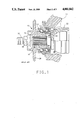
- FIG. 2 is a longitudinal section of a wheel bearing assembly for driven wheels in accordance with our invention.
- FIG. 3 is a longitudinal section of an alternate wheel bearing assembly for driven wheels in accordance with our invention.
- FIG. 1 shows a known prior art wheel bearing assembly 10 for a steerable front driven wheel of an automobile.
- the wheel bearing assembly 10 comprises an outer bearing member 12 which is secured to a steering knuckle 14 or other suitable support structure of the automobile by bolts or the like (not shown).
- the outer bearing member 12 has two integral angular contact outer raceways 16.
- the wheel bearing assembly 10 further comprises a hollow spindle or inner bearing member 18 and two rows of bearing balls 20.
- the bearing balls in each row are circumferentially spaced from each other by a conventional separator 21.
- the inner bearing member 18 has an integral angular contact inner raceway 22 and a separate pressed on race 24 which provides a second angular contact inner raceway 26.
- the rows of bearing balls 20 ride on the angular contact raceways 16, 22 and 26 and rotatably support the inner bearing member 18 in a fixed longitudinal relationship in the outer bearing member 12.
- the hollow spindle 18 has a flange 28 for mounting a vehicle wheel (not shown) in a suitable manner such as by studs and bolts.
- the hollow spindle 18 also has a splined bore 30 by means of which an outer drive member or drive bell 32 of a front wheel drive axle (not shown) is drivingly connected to the hollow spindle 18.
- the drive bell 32 has an integral stub shaft 34 which has an intermediate splined portion 36 engaging the splined bore 30 and a threaded end portion 37 which receives a nut 38 which is tightened down against a shoulder 40 of the hollow spindle 18 to secure the hollow spindle 18 on the stub shaft 34 against a shoulder 42 of the drive bell 32.
- a wheel bearing assembly 100 in accordance with our invention is shown in FIG. 2.
- the wheel bearing assembly 100 comprises an outer bearing member 112 which is secured to a steering knuckle 114 or other suitable support structure of the automobile by bolts or the like (not shown).
- the outer bearing member 112 has two integral angular contact outer raceways 116.
- the wheel bearing assembly 100 further comprises a hollow spindle or inner bearing member 118 and two rows of bearing balls 120.
- the bearing balls in each row are circumferentially spaced from each other by a conventional separator 121.
- the inner bearing member 118 has an integral angular contact inner raceway 122 and a separate race 124 which is pressed on and retained by a keeper ring 125 to provide a second angular contact inner raceway 126.
- the rows of bearing balls 120 ride on the angular contact raceways 116, 122 and 126 and rotatably support the inner bearing member 118 in a fixed longitudinal relationship in the outer bearing member 112.
- the hollow spindle 118 has a flange 128 for mounting a vehicle wheel (not shown) in a suitable manner such as by studs and bolts.
- the hollow spindle 118 also has a splined bore 130 by means of which an outer drive member or drive bell 132 of a front wheel drive axle (not shown) is drivingly connected to the hollow spindle 118 in a lash free manner.
- the drive bell 132 has an integral stub shaft 134 which has an intermediate splined portion 136 which includes a snap ring groove 138 near the free end portion 140 of the integral stub shaft 134 which has a pull groove 142.
- the wheel bearing assembly 100 also includes a Vee-shaped crush ring 144 which is disposed between the inboard end of the hollow spindle 118 and a shoulder 146 of the drive bell 132 when the integral stub shaft 134 is disposed in the splined bore 130.
- the pull groove 142 at the free end portion 140 of the integral stub shaft 134 is engaged by a tool (not shown) to pull the integral stub shaft 134 through the splined bore 130 against the resistance of the crush ring 144 until the crush ring 144 is deformed enough to align the snap ring groove 138 with a shoulder 148 of the hollow spindle 118.
- a snap ring 150 is then assembled into the snap ring groove 138.
- the assembled snap ring 150 reacts against the shoulder 148 of the hollow spindle 118 to secure the hollow spindle 118 on the stub shaft 134 against the resistance of the deformed crush ring 144 which eliminates any lash in the driving connection between the hollow spindle 118 and the drive bell 132.
- FIG. 3 An alternate wheel bearing assembly 200 in accordance with our invention is shown in FIG. 3.
- the wheel bearing assembly 200 comprises an outer bearing member 212 which is secured to a steering knuckle 214 or other suitable support structure of the automobile by bolts or the like (not shown).
- the outer bearing member 212 has two integral angular contact outer raceways 216.
- the wheel bearing assembly 200 further comprises a hollow spindle or inner bearing member 218 and two rows of bearing balls 220.
- the bearing balls in each row are circumferentially spaced from each other by a conventional separator 221.
- the inner bearing member 218 has an integral angular contact inner raceway 222 and a separate race 224 which is pressed on and retained by a keeper ring 225 to provide a second angular contact inner raceway 226.
- the rows of bearing balls 220 ride on the angular contact raceways 216, 222 and 226 and rotatably support the inner bearing member 218 in a fixed longitudinal relationship in the outer bearing member 212.
- the hollow spindle 218 has a flange 228 for mounting a vehicle wheel (not shown) in a suitable manner such as by studs and bolts.
- the hollow spindle 218 also has a splined bore 230 by means of which an outer drive member or drive bell 232 of a front wheel drive axle (not shown) is drivingly connected to the hollow spindle 218.
- the drive bell 232 has an integral stub shaft 234 which has an intermediate splined portion 236 which includes a snap ring groove 238 near the free end portion 240 of the integral stub shaft 234 which has a pull groove 242.
- the splines of the splined bore 230 are straight or parallel to the axis of the hollow spindle 218 while the splines of the intermediate splined portion 236 of the stub shaft 234 are helical.
- a helix angle of about 11 minutes at the pitch diameter is suitable.
- the pull groove 242 at the free end portion 240 of the integral stub shaft 234 is engaged by a tool (not shown) to pull the integral stub shaft 234 through the splined bore 230 against the resistance of the interengaging straight and helical spines until the snap ring groove 238 aligns with a shoulder 248 of the hollow spindle 218.
- a snap ring 250 is then assembled into the snap ring groove 238. The assembled snap ring 250 reacts against the shoulder 248 of the hollow spindle 218 to secure the hollow spindle 218 on the stub shaft 234 against the resistance of the interengaging straight and helical splines of the hollow spindle 218 and the stub shaft 234 which eliminates any lash in the driving connection.
Landscapes
- Engineering & Computer Science (AREA)
- General Engineering & Computer Science (AREA)
- Mechanical Engineering (AREA)
- Rolling Contact Bearings (AREA)
Priority Applications (2)
| Application Number | Priority Date | Filing Date | Title |
|---|---|---|---|
| US07/259,020 US4881842A (en) | 1988-10-17 | 1988-10-17 | Wheel bearing assembly |
| CA000598706A CA1316973C (fr) | 1988-10-17 | 1989-05-04 | Roulement de roue |
Applications Claiming Priority (1)
| Application Number | Priority Date | Filing Date | Title |
|---|---|---|---|
| US07/259,020 US4881842A (en) | 1988-10-17 | 1988-10-17 | Wheel bearing assembly |
Publications (1)
| Publication Number | Publication Date |
|---|---|
| US4881842A true US4881842A (en) | 1989-11-21 |
Family
ID=22983168
Family Applications (1)
| Application Number | Title | Priority Date | Filing Date |
|---|---|---|---|
| US07/259,020 Expired - Fee Related US4881842A (en) | 1988-10-17 | 1988-10-17 | Wheel bearing assembly |
Country Status (2)
| Country | Link |
|---|---|
| US (1) | US4881842A (fr) |
| CA (1) | CA1316973C (fr) |
Cited By (44)
| Publication number | Priority date | Publication date | Assignee | Title |
|---|---|---|---|---|
| US4955786A (en) * | 1988-08-20 | 1990-09-11 | Skf Kugellagerfabriken Gmbh | Drive device for pumps |
| US5141374A (en) * | 1990-07-02 | 1992-08-25 | Ab Volvo Penta | Lock nut device |
| US5366300A (en) * | 1993-06-24 | 1994-11-22 | The Budd Company | Live spindle hub with inboard bearing retention |
| EP0631896A1 (fr) * | 1993-06-24 | 1995-01-04 | The Budd Company | Assemblage de roue de véhicule |
| FR2712535A1 (fr) * | 1993-11-18 | 1995-05-24 | Gkn Automotive Ag | Unité insérable pour un montage de roulement, notamment de roue de véhicule. |
| US5536101A (en) * | 1992-09-05 | 1996-07-16 | Gkn Automotive Ag | Drive assembly for slide-on hub |
| US5553927A (en) * | 1995-03-02 | 1996-09-10 | The Budd Company | Rear axle assembly with wheel end axial retention |
| JPH08238904A (ja) * | 1994-12-15 | 1996-09-17 | Skf Ind Trading Dev Co Bv | ハブユニット及びハブユニット組立用の皿ばね並びにその組立方法 |
| US5647683A (en) * | 1994-04-05 | 1997-07-15 | Dana Corporation | Axle and tube yoke attachment |
| US5762439A (en) * | 1996-12-26 | 1998-06-09 | Siner; Irwin H | Servo-member and method of making |
| EP0936086A2 (fr) | 1998-02-16 | 1999-08-18 | Nsk Ltd | Essieu pour roue motrice de véhicule |
| US6012986A (en) * | 1996-02-27 | 2000-01-11 | Gkn Automotive Ag | Rotational coupling of a wheel flange to the output member of a transmission joint |
| US6017097A (en) * | 1997-12-29 | 2000-01-25 | Weir, Iii; Robert Spence | Wheel hub assembly |
| US6254196B1 (en) | 1999-12-21 | 2001-07-03 | Thomas A Gee | Axle hub assembly with removable axle shaft |
| US6488589B2 (en) | 2000-02-16 | 2002-12-03 | Nsk Ltd. | Apparatus for driving wheel of automobile |
| US6557947B1 (en) * | 2001-04-27 | 2003-05-06 | Torque-Traction Technologies, Inc. | Three quarter floating automotive axle |
| WO2003057512A1 (fr) * | 2001-12-27 | 2003-07-17 | The Timken Company | Extremite cote roue solidarisee |
| US20030146591A1 (en) * | 2000-05-31 | 2003-08-07 | Hideo Ouchi | Wheel driving unit and method of manufacturing the same |
| EP1177918A3 (fr) * | 2000-07-31 | 2003-10-08 | Nsk Ltd | Unité d'entraínement pour les roues d'un véhicule et sa méthode d'assemblage |
| DE10219018A1 (de) * | 2002-04-27 | 2003-12-18 | Gkn Automotive Gmbh | Radnabeneinheit |
| US6749517B2 (en) | 2000-08-22 | 2004-06-15 | Nsk Ltd. | Wheel drive unit |
| US20040124696A1 (en) * | 2002-11-20 | 2004-07-01 | Brunner Drilling And Manufacturing Inc. | Dust cup and wheel spindle |
| US20040131295A1 (en) * | 2001-04-04 | 2004-07-08 | Eishi Shibuya | Wheel drive unit |
| US20040183272A1 (en) * | 1999-06-03 | 2004-09-23 | Kamen Dean L. | Mechanical improvements to a personal vehicle |
| US20040250619A1 (en) * | 2001-10-16 | 2004-12-16 | Junshi Sakamoto | Rotation-support apparatus with rotation sensor device for drive-wheel |
| US20050248213A1 (en) * | 2004-05-05 | 2005-11-10 | Gary Grabaum | Shaft and wheel hub retention assembly |
| US20050254890A1 (en) * | 2002-08-28 | 2005-11-17 | Horst Schulz | Shaft-hub connection |
| US20060017036A1 (en) * | 2004-07-22 | 2006-01-26 | Visteon Global Technologies, Inc. | Throttle body and method of assembly |
| WO2006073159A1 (fr) * | 2005-01-07 | 2006-07-13 | Honda Motor Co., Ltd. | Dispositif pour palier de roue motrice |
| JP2006188175A (ja) * | 2005-01-07 | 2006-07-20 | Honda Motor Co Ltd | 駆動輪用軸受装置 |
| US20060157663A1 (en) * | 2004-07-22 | 2006-07-20 | James Rauch | Throttle body and method of assembly |
| WO2006109499A1 (fr) * | 2005-03-31 | 2006-10-19 | Honda Motor Co., Ltd. | Dispositif de palier pour roue d'entrainement |
| JP2006281959A (ja) * | 2005-03-31 | 2006-10-19 | Honda Motor Co Ltd | 駆動輪用軸受装置 |
| EP1738927A1 (fr) * | 2005-06-30 | 2007-01-03 | Ford Global Technologies, LLC | Connection par écrou sans jeu entre un assemblage d'un moyeu de roue et la fin d'un arbre articulé de construction étroite |
| US20070177939A1 (en) * | 2006-01-27 | 2007-08-02 | Kozlowski Keith A | Spline arrangement for rotatably coupling two members |
| US20100092122A1 (en) * | 2007-03-07 | 2010-04-15 | Yoshikazu Fukumura | Bearing device for driving wheel, and its assembling method |
| US20100257737A1 (en) * | 2009-02-20 | 2010-10-14 | Robert Veldman | Wheel assembly and method for making same |
| US20110069922A1 (en) * | 2009-09-21 | 2011-03-24 | Diversified Machine Inc. | Wheel bearing retainer |
| FR2990253A1 (fr) * | 2012-05-03 | 2013-11-08 | Ntn Snr Roulements | Systeme d'entrainement en rotation d'une roue de vehicule automobile |
| US8616779B2 (en) | 2010-11-29 | 2013-12-31 | Honda Motor Co., Ltd. | Shortened driveshaft stem |
| DE102011012942B4 (de) * | 2010-03-10 | 2015-11-19 | GM Global Technology Operations LLC (n. d. Gesetzen des Staates Delaware) | Radlagerung |
| WO2018013130A1 (fr) * | 2016-07-15 | 2018-01-18 | Ford Global Technologies, Llc | Dispositif de puissance auxiliaire |
| US20180022154A1 (en) * | 2016-07-25 | 2018-01-25 | Arvinmeritor Technology, Llc | Axle Assembly Having an Axle Shaft Subassembly |
| WO2024043097A1 (fr) * | 2022-08-24 | 2024-02-29 | Ntn株式会社 | Dispositif de roulement de roue |
Citations (4)
| Publication number | Priority date | Publication date | Assignee | Title |
|---|---|---|---|---|
| US2136155A (en) * | 1936-02-26 | 1938-11-08 | Gen Motors Corp | Locking device for bearings and the like |
| US4424047A (en) * | 1980-11-11 | 1984-01-03 | Lo/ hr & Bromkamp GmbH | Wheel bearing assembly |
| US4427085A (en) * | 1980-03-11 | 1984-01-24 | Lohr & Bromkamp Gmbh | Wheel support assembly for a motor vehicle |
| US4529254A (en) * | 1982-03-17 | 1985-07-16 | Uni-Cardan Aktiengesellschaft | Wheel mounting assembly |
-
1988
- 1988-10-17 US US07/259,020 patent/US4881842A/en not_active Expired - Fee Related
-
1989
- 1989-05-04 CA CA000598706A patent/CA1316973C/fr not_active Expired - Fee Related
Patent Citations (4)
| Publication number | Priority date | Publication date | Assignee | Title |
|---|---|---|---|---|
| US2136155A (en) * | 1936-02-26 | 1938-11-08 | Gen Motors Corp | Locking device for bearings and the like |
| US4427085A (en) * | 1980-03-11 | 1984-01-24 | Lohr & Bromkamp Gmbh | Wheel support assembly for a motor vehicle |
| US4424047A (en) * | 1980-11-11 | 1984-01-03 | Lo/ hr & Bromkamp GmbH | Wheel bearing assembly |
| US4529254A (en) * | 1982-03-17 | 1985-07-16 | Uni-Cardan Aktiengesellschaft | Wheel mounting assembly |
Cited By (85)
| Publication number | Priority date | Publication date | Assignee | Title |
|---|---|---|---|---|
| US4955786A (en) * | 1988-08-20 | 1990-09-11 | Skf Kugellagerfabriken Gmbh | Drive device for pumps |
| US5141374A (en) * | 1990-07-02 | 1992-08-25 | Ab Volvo Penta | Lock nut device |
| AU644445B2 (en) * | 1990-07-02 | 1993-12-09 | Ab Volvo Penta | Lock nut device |
| US5536101A (en) * | 1992-09-05 | 1996-07-16 | Gkn Automotive Ag | Drive assembly for slide-on hub |
| US5443316A (en) * | 1993-06-24 | 1995-08-22 | The Budd Company | Live spindle hub with inboard bearing retention |
| EP0631896A1 (fr) * | 1993-06-24 | 1995-01-04 | The Budd Company | Assemblage de roue de véhicule |
| US5366300A (en) * | 1993-06-24 | 1994-11-22 | The Budd Company | Live spindle hub with inboard bearing retention |
| FR2712535A1 (fr) * | 1993-11-18 | 1995-05-24 | Gkn Automotive Ag | Unité insérable pour un montage de roulement, notamment de roue de véhicule. |
| US5647683A (en) * | 1994-04-05 | 1997-07-15 | Dana Corporation | Axle and tube yoke attachment |
| JPH08238904A (ja) * | 1994-12-15 | 1996-09-17 | Skf Ind Trading Dev Co Bv | ハブユニット及びハブユニット組立用の皿ばね並びにその組立方法 |
| US5720530A (en) * | 1994-12-15 | 1998-02-24 | Skf Industrial Trading And Development Company B.V. | Hub unit with connection by means of cup spring |
| US5553927A (en) * | 1995-03-02 | 1996-09-10 | The Budd Company | Rear axle assembly with wheel end axial retention |
| US6012986A (en) * | 1996-02-27 | 2000-01-11 | Gkn Automotive Ag | Rotational coupling of a wheel flange to the output member of a transmission joint |
| US5762439A (en) * | 1996-12-26 | 1998-06-09 | Siner; Irwin H | Servo-member and method of making |
| US6017097A (en) * | 1997-12-29 | 2000-01-25 | Weir, Iii; Robert Spence | Wheel hub assembly |
| US6135571A (en) * | 1998-02-16 | 2000-10-24 | Nsk, Ltd. | Axle unit for driving a vehicle wheel |
| EP1308315A2 (fr) | 1998-02-16 | 2003-05-07 | Nsk Ltd | Essieu pour roue motrice de véhicule |
| EP0936086A3 (fr) * | 1998-02-16 | 2001-05-02 | Nsk Ltd | Essieu pour roue motrice de véhicule |
| EP1077142A3 (fr) * | 1998-02-16 | 2001-05-02 | Nsk Ltd | Essieu pour roue motrice de véhicule |
| EP0936086A2 (fr) | 1998-02-16 | 1999-08-18 | Nsk Ltd | Essieu pour roue motrice de véhicule |
| US6286909B1 (en) | 1998-02-16 | 2001-09-11 | Nsk Ltd. | Axle unit for driving a vehicle wheel |
| US6296321B1 (en) | 1998-02-16 | 2001-10-02 | Nsk Ltd. | Axle unit for driving a vehicle wheel |
| EP1308314A3 (fr) * | 1998-02-16 | 2003-08-13 | Nsk Ltd | Essieu pour roue motrice de véhicule |
| EP1308315A3 (fr) * | 1998-02-16 | 2003-08-13 | Nsk Ltd | Essieu pour roue motrice de véhicule |
| EP1308314A2 (fr) | 1998-02-16 | 2003-05-07 | Nsk Ltd | Essieu pour roue motrice de véhicule |
| US20040183272A1 (en) * | 1999-06-03 | 2004-09-23 | Kamen Dean L. | Mechanical improvements to a personal vehicle |
| US7131706B2 (en) * | 1999-06-03 | 2006-11-07 | Deka Products Limited Partnership | Mechanical improvements to a personal vehicle |
| US6254196B1 (en) | 1999-12-21 | 2001-07-03 | Thomas A Gee | Axle hub assembly with removable axle shaft |
| US6488589B2 (en) | 2000-02-16 | 2002-12-03 | Nsk Ltd. | Apparatus for driving wheel of automobile |
| EP1125765A3 (fr) * | 2000-02-16 | 2004-12-22 | Nsk Ltd | Dispositif pour roue motrice d'un véhicule à moteur |
| US7104893B2 (en) | 2000-05-31 | 2006-09-12 | Nsk Ltd. | Wheel drive unit |
| US20030146591A1 (en) * | 2000-05-31 | 2003-08-07 | Hideo Ouchi | Wheel driving unit and method of manufacturing the same |
| US20050159227A1 (en) * | 2000-05-31 | 2005-07-21 | Nsk Ltd. | Wheel-driving unit and method for manufacturing the same |
| US6851866B2 (en) * | 2000-07-31 | 2005-02-08 | Nsk Ltd. | Drive unit for wheel and assembly method for the same |
| EP1177918A3 (fr) * | 2000-07-31 | 2003-10-08 | Nsk Ltd | Unité d'entraínement pour les roues d'un véhicule et sa méthode d'assemblage |
| US6749517B2 (en) | 2000-08-22 | 2004-06-15 | Nsk Ltd. | Wheel drive unit |
| US20040131295A1 (en) * | 2001-04-04 | 2004-07-08 | Eishi Shibuya | Wheel drive unit |
| US6981800B2 (en) | 2001-04-04 | 2006-01-03 | Nsk Ltd. | Wheel drive unit |
| US6557947B1 (en) * | 2001-04-27 | 2003-05-06 | Torque-Traction Technologies, Inc. | Three quarter floating automotive axle |
| US20040250619A1 (en) * | 2001-10-16 | 2004-12-16 | Junshi Sakamoto | Rotation-support apparatus with rotation sensor device for drive-wheel |
| US7281424B2 (en) * | 2001-10-16 | 2007-10-16 | Nsk Ltd. | Rotation-support apparatus with rotation sensor device for drive-wheel |
| WO2003057512A1 (fr) * | 2001-12-27 | 2003-07-17 | The Timken Company | Extremite cote roue solidarisee |
| DE10219018B8 (de) * | 2002-04-27 | 2004-10-28 | Gkn Driveline International Gmbh | Radnabeneinheit |
| US6821208B2 (en) | 2002-04-27 | 2004-11-23 | Gkn Automotive Gmbh | Wheel hub unit |
| DE10219018A1 (de) * | 2002-04-27 | 2003-12-18 | Gkn Automotive Gmbh | Radnabeneinheit |
| DE10219018B4 (de) * | 2002-04-27 | 2004-07-15 | Gkn Automotive Gmbh | Radnabeneinheit |
| US20050254890A1 (en) * | 2002-08-28 | 2005-11-17 | Horst Schulz | Shaft-hub connection |
| US20040124696A1 (en) * | 2002-11-20 | 2004-07-01 | Brunner Drilling And Manufacturing Inc. | Dust cup and wheel spindle |
| US7121632B2 (en) * | 2004-05-05 | 2006-10-17 | Gkn Driveline North Amercia, Inc. | Shaft and wheel hub retention assembly |
| US20050248213A1 (en) * | 2004-05-05 | 2005-11-10 | Gary Grabaum | Shaft and wheel hub retention assembly |
| US20060157663A1 (en) * | 2004-07-22 | 2006-07-20 | James Rauch | Throttle body and method of assembly |
| US7032885B2 (en) | 2004-07-22 | 2006-04-25 | Automotive Components Holdings, Llc | Throttle body and method of assembly |
| US7574797B2 (en) | 2004-07-22 | 2009-08-18 | Ford Global Technologies, Llc | Throttle body and method of assembly |
| US20060017036A1 (en) * | 2004-07-22 | 2006-01-26 | Visteon Global Technologies, Inc. | Throttle body and method of assembly |
| JP2006188175A (ja) * | 2005-01-07 | 2006-07-20 | Honda Motor Co Ltd | 駆動輪用軸受装置 |
| WO2006073159A1 (fr) * | 2005-01-07 | 2006-07-13 | Honda Motor Co., Ltd. | Dispositif pour palier de roue motrice |
| US7833105B2 (en) | 2005-01-07 | 2010-11-16 | Honda Motor Co., Ltd. | Bearing device for drive wheel |
| US20080285902A1 (en) * | 2005-01-07 | 2008-11-20 | Honda Motor Co., Ltd. | Bearing Device for Drive Wheel |
| US20080131045A1 (en) * | 2005-03-31 | 2008-06-05 | Yasuhisa Nagayama | Bearing Device for Drive Wheel |
| US7819588B2 (en) | 2005-03-31 | 2010-10-26 | Honda Motor Co., Ltd. | Bearing device for drive wheel |
| JP2006281959A (ja) * | 2005-03-31 | 2006-10-19 | Honda Motor Co Ltd | 駆動輪用軸受装置 |
| WO2006109499A1 (fr) * | 2005-03-31 | 2006-10-19 | Honda Motor Co., Ltd. | Dispositif de palier pour roue d'entrainement |
| EP1738927A1 (fr) * | 2005-06-30 | 2007-01-03 | Ford Global Technologies, LLC | Connection par écrou sans jeu entre un assemblage d'un moyeu de roue et la fin d'un arbre articulé de construction étroite |
| US7478969B2 (en) | 2006-01-27 | 2009-01-20 | Delphi Technologies, Inc | Spline arrangement for rotatably coupling two members |
| US20070177939A1 (en) * | 2006-01-27 | 2007-08-02 | Kozlowski Keith A | Spline arrangement for rotatably coupling two members |
| US8944694B2 (en) * | 2007-03-07 | 2015-02-03 | Ntn Corporation | Bearing device for driving wheel, and its assembling method |
| US20100092122A1 (en) * | 2007-03-07 | 2010-04-15 | Yoshikazu Fukumura | Bearing device for driving wheel, and its assembling method |
| US20100257737A1 (en) * | 2009-02-20 | 2010-10-14 | Robert Veldman | Wheel assembly and method for making same |
| US9120195B2 (en) | 2009-02-20 | 2015-09-01 | Diversified Machine, Inc. | Wheel assembly and method for making same |
| US9272575B2 (en) | 2009-09-21 | 2016-03-01 | Diversified Machine, Inc. | Wheel bearing retainer |
| US8740467B2 (en) | 2009-09-21 | 2014-06-03 | Diversified Machine, Inc. | Wheel bearing retainer |
| US20110069922A1 (en) * | 2009-09-21 | 2011-03-24 | Diversified Machine Inc. | Wheel bearing retainer |
| US9610801B2 (en) | 2009-09-21 | 2017-04-04 | Diversified Machine Inc. | Wheel bearing retainer and methods thereof |
| DE102011012942B4 (de) * | 2010-03-10 | 2015-11-19 | GM Global Technology Operations LLC (n. d. Gesetzen des Staates Delaware) | Radlagerung |
| US8616779B2 (en) | 2010-11-29 | 2013-12-31 | Honda Motor Co., Ltd. | Shortened driveshaft stem |
| FR2990253A1 (fr) * | 2012-05-03 | 2013-11-08 | Ntn Snr Roulements | Systeme d'entrainement en rotation d'une roue de vehicule automobile |
| WO2018013130A1 (fr) * | 2016-07-15 | 2018-01-18 | Ford Global Technologies, Llc | Dispositif de puissance auxiliaire |
| CN109475456A (zh) * | 2016-07-15 | 2019-03-15 | 福特全球技术公司 | 辅助动力装置 |
| CN109475456B (zh) * | 2016-07-15 | 2021-03-05 | 福特全球技术公司 | 辅助动力装置 |
| US11155147B2 (en) | 2016-07-15 | 2021-10-26 | Ford Global Technologies, Llc | Auxiliary power device |
| US20180022154A1 (en) * | 2016-07-25 | 2018-01-25 | Arvinmeritor Technology, Llc | Axle Assembly Having an Axle Shaft Subassembly |
| US10752050B2 (en) * | 2016-07-25 | 2020-08-25 | Arvinmeritor Technology, Llc | Axle assembly having an axle shaft subassembly |
| WO2024043097A1 (fr) * | 2022-08-24 | 2024-02-29 | Ntn株式会社 | Dispositif de roulement de roue |
| JP2024030417A (ja) * | 2022-08-24 | 2024-03-07 | Ntn株式会社 | 車輪用軸受装置 |
| JP7828854B2 (ja) | 2022-08-24 | 2026-03-12 | Ntn株式会社 | 車輪用軸受装置 |
Also Published As
| Publication number | Publication date |
|---|---|
| CA1316973C (fr) | 1993-04-27 |
Similar Documents
| Publication | Publication Date | Title |
|---|---|---|
| CA1330573C (fr) | Arbre d'essieu a grande capacite de couple | |
| CA1316973C (fr) | Roulement de roue | |
| US6450585B1 (en) | Wheel suspension assembly | |
| US7086983B2 (en) | Differential with pinion bearings supported on input yoke | |
| US5052979A (en) | Shaft assembly for the wheel drive of a motor vehicle | |
| EP1320464B1 (fr) | Palier de roue motrice | |
| EP0181654A1 (fr) | Palier à roulement | |
| US12078205B2 (en) | Motor vehicle wheel assembly | |
| US6719661B2 (en) | Differential with pinion bearings supported on input yoke | |
| JP2003097588A (ja) | 自動車駆動輪ハブユニット | |
| US5711393A (en) | Drive axle assembly with screw cap | |
| US4046433A (en) | Wheel bearing unit for motor vehicles | |
| US4331210A (en) | Live spindle vehicle drive wheel assembly with axially moveable axle | |
| JP2001225605A (ja) | 自動車用車輪駆動装置 | |
| JP3869197B2 (ja) | 車両用軸受装置 | |
| US20080238184A1 (en) | Outer Joint Part Of A Constant Velocity Universal Joint For A Wheel Hub-Joint-Unit | |
| US20040022469A1 (en) | Wheel bearing device | |
| US20060023984A1 (en) | Bearing apparatus for a driving wheel of vehicle | |
| US6880841B2 (en) | Integrated wheel end for a wheel suspension of a motor vehicle | |
| US7195399B2 (en) | Wheelend assembly with detachable outboard joint | |
| US20030063827A1 (en) | Compact hub assembly for automotive vehicles | |
| JP2001113906A (ja) | 車輪駆動用軸受ユニット | |
| US20020114552A1 (en) | Constant velocity joint integrated to wheel bearing and to axially adjustable hub | |
| JP2001163003A (ja) | 車輪駆動用軸受ユニット及び車輪駆動用軸受ユニット用結合部材の製造方法 | |
| US6991380B2 (en) | Wheelend assembly with detachable outboard joint |
Legal Events
| Date | Code | Title | Description |
|---|---|---|---|
| AS | Assignment |
Owner name: GENERAL MOTORS CORPORATION, DETROIT, MICHIGAN, A C Free format text: ASSIGNMENT OF ASSIGNORS INTEREST.;ASSIGNORS:FARRELL, ROBERT C.;LUNDY, GEORGE A.;REEL/FRAME:004987/0767;SIGNING DATES FROM 19881116 TO 19881117 Owner name: GENERAL MOTORS CORPORATION, A CORP. OF DE, MICHIG Free format text: ASSIGNMENT OF ASSIGNORS INTEREST;ASSIGNORS:FARRELL, ROBERT C.;LUNDY, GEORGE A.;SIGNING DATES FROM 19881116 TO 19881117;REEL/FRAME:004987/0767 |
|
| REMI | Maintenance fee reminder mailed | ||
| FPAY | Fee payment |
Year of fee payment: 4 |
|
| SULP | Surcharge for late payment | ||
| FPAY | Fee payment |
Year of fee payment: 8 |
|
| REMI | Maintenance fee reminder mailed | ||
| LAPS | Lapse for failure to pay maintenance fees | ||
| STCH | Information on status: patent discontinuation |
Free format text: PATENT EXPIRED DUE TO NONPAYMENT OF MAINTENANCE FEES UNDER 37 CFR 1.362 |
|
| FP | Lapsed due to failure to pay maintenance fee |
Effective date: 20011121 |