US4883972A - Monitoring equipment for detection of emission - Google Patents
Monitoring equipment for detection of emission Download PDFInfo
- Publication number
- US4883972A US4883972A US07/190,757 US19075788A US4883972A US 4883972 A US4883972 A US 4883972A US 19075788 A US19075788 A US 19075788A US 4883972 A US4883972 A US 4883972A
- Authority
- US
- United States
- Prior art keywords
- light
- unit
- light source
- detector
- monitoring equipment
- Prior art date
- Legal status (The legal status is an assumption and is not a legal conclusion. Google has not performed a legal analysis and makes no representation as to the accuracy of the status listed.)
- Expired - Fee Related
Links
- 238000012544 monitoring process Methods 0.000 title claims abstract description 24
- 238000001514 detection method Methods 0.000 title description 3
- 239000000779 smoke Substances 0.000 claims abstract description 17
- 239000011236 particulate material Substances 0.000 claims abstract description 5
- 238000011109 contamination Methods 0.000 claims description 14
- XUIMIQQOPSSXEZ-UHFFFAOYSA-N Silicon Chemical compound [Si] XUIMIQQOPSSXEZ-UHFFFAOYSA-N 0.000 claims description 4
- 229910052710 silicon Inorganic materials 0.000 claims description 4
- 239000010703 silicon Substances 0.000 claims description 4
- 239000002131 composite material Substances 0.000 claims 1
- 238000010276 construction Methods 0.000 abstract description 4
- 239000002803 fossil fuel Substances 0.000 abstract description 2
- 239000010419 fine particle Substances 0.000 abstract 3
- 230000031700 light absorption Effects 0.000 abstract 1
- 239000000428 dust Substances 0.000 description 10
- 238000005259 measurement Methods 0.000 description 8
- 230000003287 optical effect Effects 0.000 description 7
- 230000000694 effects Effects 0.000 description 5
- 238000000034 method Methods 0.000 description 5
- 238000002485 combustion reaction Methods 0.000 description 4
- 230000000737 periodic effect Effects 0.000 description 4
- 238000006243 chemical reaction Methods 0.000 description 2
- 230000007935 neutral effect Effects 0.000 description 2
- 230000005855 radiation Effects 0.000 description 2
- 238000002310 reflectometry Methods 0.000 description 2
- 238000012360 testing method Methods 0.000 description 2
- 230000005540 biological transmission Effects 0.000 description 1
- 238000004140 cleaning Methods 0.000 description 1
- 239000000356 contaminant Substances 0.000 description 1
- 230000001419 dependent effect Effects 0.000 description 1
- 230000008030 elimination Effects 0.000 description 1
- 238000003379 elimination reaction Methods 0.000 description 1
- 239000000446 fuel Substances 0.000 description 1
- 238000003780 insertion Methods 0.000 description 1
- 230000037431 insertion Effects 0.000 description 1
- 238000009434 installation Methods 0.000 description 1
- 238000011896 sensitive detection Methods 0.000 description 1
- 238000001429 visible spectrum Methods 0.000 description 1
Images

Classifications
-
- G—PHYSICS
- G01—MEASURING; TESTING
- G01N—INVESTIGATING OR ANALYSING MATERIALS BY DETERMINING THEIR CHEMICAL OR PHYSICAL PROPERTIES
- G01N21/00—Investigating or analysing materials by the use of optical means, i.e. using sub-millimetre waves, infrared, visible or ultraviolet light
- G01N21/17—Systems in which incident light is modified in accordance with the properties of the material investigated
- G01N21/47—Scattering, i.e. diffuse reflection
- G01N21/49—Scattering, i.e. diffuse reflection within a body or fluid
- G01N21/53—Scattering, i.e. diffuse reflection within a body or fluid within a flowing fluid, e.g. smoke
- G01N21/534—Scattering, i.e. diffuse reflection within a body or fluid within a flowing fluid, e.g. smoke by measuring transmission alone, i.e. determining opacity
-
- G—PHYSICS
- G01—MEASURING; TESTING
- G01N—INVESTIGATING OR ANALYSING MATERIALS BY DETERMINING THEIR CHEMICAL OR PHYSICAL PROPERTIES
- G01N21/00—Investigating or analysing materials by the use of optical means, i.e. using sub-millimetre waves, infrared, visible or ultraviolet light
- G01N21/17—Systems in which incident light is modified in accordance with the properties of the material investigated
- G01N21/47—Scattering, i.e. diffuse reflection
- G01N21/49—Scattering, i.e. diffuse reflection within a body or fluid
- G01N21/53—Scattering, i.e. diffuse reflection within a body or fluid within a flowing fluid, e.g. smoke
- G01N21/534—Scattering, i.e. diffuse reflection within a body or fluid within a flowing fluid, e.g. smoke by measuring transmission alone, i.e. determining opacity
- G01N2021/536—Measurement device mounted at stack
-
- G—PHYSICS
- G01—MEASURING; TESTING
- G01N—INVESTIGATING OR ANALYSING MATERIALS BY DETERMINING THEIR CHEMICAL OR PHYSICAL PROPERTIES
- G01N2201/00—Features of devices classified in G01N21/00
- G01N2201/06—Illumination; Optics
- G01N2201/062—LED's
- G01N2201/0621—Supply
-
- G—PHYSICS
- G01—MEASURING; TESTING
- G01N—INVESTIGATING OR ANALYSING MATERIALS BY DETERMINING THEIR CHEMICAL OR PHYSICAL PROPERTIES
- G01N2201/00—Features of devices classified in G01N21/00
- G01N2201/06—Illumination; Optics
- G01N2201/066—Modifiable path; multiple paths in one sample
- G01N2201/0664—Using two ways, i.e. two devices in same path in one sample
-
- G—PHYSICS
- G01—MEASURING; TESTING
- G01N—INVESTIGATING OR ANALYSING MATERIALS BY DETERMINING THEIR CHEMICAL OR PHYSICAL PROPERTIES
- G01N2201/00—Features of devices classified in G01N21/00
- G01N2201/12—Circuits of general importance; Signal processing
- G01N2201/128—Alternating sample and standard or reference part in one path
- G01N2201/1281—Reflecting part, i.e. for autocollimation
Definitions
- This invention relates to monitoring equipment and is particularly although not necessarily exclusively concerned with the monitoring of smoke and fine particulate material (dust) emissions from fossil fuel combustion systems.
- Such systems that are primarily intended for the detection of smoke need not be particularly accurate and can be of relatively simple construction and of relatively low cost.
- such systems that are to provide effective monitoring of dust existing in a flue or chimney need to be of much greater accuracy and tend to be complex structures of relatively high cost.
- monitoring equipment for smoke and/or fine particulate material emissions comprises two units for location to opposite sides of a flue or chimney each unit comprising a light source, a lens and a light detector, the light from the light source of each said unit being directed by its lens across the flue or chimney in a divergence path, to be gathered by the lens of the opposite unit and directed to the detector in the opposite unit, the outputs from the detectors of each unit being combined to provide a reading of the degree of smoke and/or fine particulate material existing in the flue or chimney.
- a reflecting mirror can be introduced between each unit and the flue or chimney.
- the reflecting mirror can be manually applied and removed, giving the opportunity of cleaning the mirror before calibration takes place.
- monitoring dust it is frequently so that automatic calibration must be provided for.
- a means of preventing the contamination of a calibrating mirror comprises locating a calibrating mirror on a plug member rotatable within a housing, said plug member having a through hole with an axis parallel to the plane of the mirror the plug member being rotatable from a first position where the through hole provides a sight path between a light source and a directing lens and when the mirror lies within the housing, to a second position where the mirror is located in the sight path to reflect light from the light source to a strategically located detector.
- Rotation of the plug and its mirror can be effected by any suitable means, such as by a solenoid or by a stepping motor.
- the light source in each said unit is a high intensity light emitting diode (LED) and which has the threefold advantage of a long working life, only requiring low power for effective operation, and can be modulated electronically to provide pulsed light at an effective wavelength for the light, and which is further preferably between 500 and 700 nanometers in the visible spectrum.
- LED light emitting diode
- the ability to provide required pulsed frequencies has the advantage that the light source in each unit can be pulsed at two different frequencies, and the detector signals can be separated into the components of those frequencies, to enable the precise identification of the light from each source and additionally allow the elimination of the effects of any stray light source that is received by either detector.
- the two light sources can be modulated by signals produced by combining the two different frequencies in such a way that the light source of one unit is modulated by the AND function of the two frequencies whilst the light source of the other unit is modulated by the AND function of one frequency and the inverse of the other frequency. In this way, only one light source is illuminated at any one time, thereby simplifying the means of identifying the light from each source.
- the invention avoids the need to reflect light back across the flue or chimney and hence avoids potential problems by contamination present on a main reflecting mirror and which would have an inevitable effect on the readings provided by the system.
- the degree of alignment as between the units to each side of the flue or chimney is considerably less critical than in any system known hitherto.
- misalignment as high as 30 can be tolerated without affecting the accuracy of the readings from the system. It is equally so that in addition to being able to tolerate a degree of misalignment, the system also allows for the automatic checking that misalignment is not at an unacceptably high level as will be discussed below.
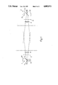
- FIG. 1 is a schematic view of the invention located on a flue or chimney;
- FIG. 2 is a sectional side elevation of one embodiment of calibrating lens mounting means.
- FIG. 1 there is the schematic representation of the monitoring system of the invention.
- the unit 1 having a light source L 1 and a light detector D 1
- the unit 2 having a light source L 2 and a light detector D 2
- a beam splitter 3 is provided to allow a light beam to be transmitted across the flue or chimney, and to direct incoming light on to detector D 1 or D 2 .
- Each unit 1 and 2 has a lens 4, to direct a light beam across the flue or chimney in a divergent path, and to gather incoming radiation for direction at the beam splitter 3.
- the beam splitters 3 additionally direct light from the light sources L 1 and L 2 to mirrors 3A for reflection back to the respective detectors D 1 and D.sub. 2 of the units each detector being such as to be capable of receiving and distinguishing between the radiation from both light sources, and when calibration of the system is required, a mirror 5 can be introduced manually or automatically between the lens and the flue or chimney and when light from each light source L 1 and L 2 is reflected back to the detector D 1 and D 2 respectively.
- the two transmitter/receiver units 1 and 2 have identical optical configurations. Each consists of an LED and a silicon detector arranged as shown in FIG. 1. Each detector can monitor light received from both its own neighbouring LED and that transmitted from the opposite unit. By modulating the two LEDs at different frequencies the two light levels can be resolved by phase sensitive detection techniques.
- the transmissivity of light from Unit 2 to Unit 1 is the transmissivity of light from Unit 2 to Unit 1
- G 2 is a gain constant and D 1 is the signal provided by detector D 1 from light received from LED 2 at frequency f 2 ; D 2 is the signal provided by detector D 2 from LED 2 at frequency f 2 .
- the measurement can thus be made independant of any drift of either detector 1 or detector 2.
- the required calibration check can be made at each unit by placing a mirror in front of each lens.
- First Unit 1 The detector output when the calibration mirror is in place is
- T 1 is the transmissivity of the lens surface (Note the double pass requires T 1 2 ) and K is a constant depending upon the reflectivities of the internal optical system.
- D 1 is the detector output from light from LED 1 at frequency f 1 immediately prior to the calibration mirror being inserted.
- T 1 2 (D 1cal -D 1 )/K.D 1 from which function the effective lens contamination can be calculated.
- This calibration procedure can also be made for Unit 2 enabling the contamination of each lens to be monitored and if necessary compensated for.
- the double pass applies both for the calibration procedure and for the normal measurement mode which is also effectively a double pass system since the transmissivity of light from Unit 1 to 2 taking into account the transmissivity of the lens is
- the zero check output for the system may be displayed as
- the two LEDs are modulated by signals produced by combining the two different frequencies f 1 and f 2 in such a way that LED 1 is modulated by the AND function of f 1 and f 2 while LED 2 is modulated by the AND function of f 1 and the inverse of f 2 (f 2 ).
- LED 1 is modulated by the AND function of f 1 and f 2
- LED 2 is modulated by the AND function of f 1 and the inverse of f 2 (f 2 ).
- f 2 the transmissivity of light from Unit 1 to Unit 2 is obtained from the relation
- the transmissivity of light from Unit 2 to Unit 1 is the transmissivity of light from Unit 2 to Unit 1
- G 2 is a gain constant and D 12 is the signal provided by detector D 1 from light received from LED 2; D 22 is the signal provided by detector D 2 from LED 2. The resultant transmissivity of the light over the two passes is obtained from the expression
- the measurement can thus be made independent of any drift of either detector 1 or Detector 2.
- the required calibration check can be made at each unit by placing a mirror in front of each lens.
- the detector output when the calibration mirror is in place is
- T 1 is the transmissivity of the lens surface (Note double pass requires T 1 2 ) and K is a constant depending upon the reflectivities of the internal optical system.
- D 11 is the detector output from the light from LED 1 immediately prior to the calibration mirror being inserted.
- T 1 2 (D 11cal -D 11 )/K ⁇ D 11 from which function the effective lens contamination can be calculated.
- This calibration procedure can also be made for Unit 2 enabling the contamination of each lens to be monitored and if necessary compensated for.
- the double pass applies both for the calibration procedure and for the normal measurement mode which is also effectively a double pass system since the transmissivity of light from Unit 1 to 2 taking into account the transmissivity of the lens is
- the zero check output for the system may be displayed as
- D 1cal is the zero check detector level found during the zero check cycle immediately preceding.
- the span check output of the system can be shown as ##EQU1## m 1 and m 2 , the reduction ratios of the span check LED currents, can be selected to provide a span check at any point on the instrument scale, for any range of output, without the need to select and change optical filters as with existing equipment. Additionally since m 1 and m 2 are both checked independently any error can be immediately traced to one of the two units.
- the output of the instrument is independent of drift of either detector D1 or D2.
- the characteristics of silicon cell detectors used in this system are such that drift with temperature is virtually eliminated by the use of a specific wavelength of light remote from the silicon cell long wavelength cut off point at approximately 1100 nanometers which is the temperature sensitive part of the cell characteristic. This means that while the instrument is still independent of detector drift it is still possible to keep such drift down to a minimum. This enables transmissivity measurements to be assessed for each direction of transmission creating the possibility of detecting changes in optical alignment.
- FIG. 2 shows a means of keeping a reflecting mirror free from contamination.
- a housing 6 within which is a stepping motor 7 secured to and able to rotate when required, a cylidrical plug member 8 located in a cylindrical bore 9.
- the plug member 8 has a through bore 10 to align with ports 11 in the walls of the bore and a reflecting mirror 12 set within a recess in the wall of the plug, with the plane of the mirror parallel to longitudinal axis of the through bore 10.
- the plug can be set in a position such that the through bore 10 is aligned with the ports 11, to provide a continuous sight path from a light source to a detector located within the housing. In this position, the mirror lies wholly within the cylindrical bore 9 and is thus shielded and substantially prevented from being contaminated.
- the stepping motor is activated to rotate the plug member 8 to bring the clean reflecting mirror into position, the through bore 10 now being closed by the cylindrical bore 9 again to prevent any contaminants from reaching the mirror 12.
Landscapes
- General Health & Medical Sciences (AREA)
- General Physics & Mathematics (AREA)
- Life Sciences & Earth Sciences (AREA)
- Chemical & Material Sciences (AREA)
- Analytical Chemistry (AREA)
- Biochemistry (AREA)
- Immunology (AREA)
- Physics & Mathematics (AREA)
- Health & Medical Sciences (AREA)
- Pathology (AREA)
- Investigating Or Analysing Materials By Optical Means (AREA)
- Forging (AREA)
- Optical Communication System (AREA)
- Crystals, And After-Treatments Of Crystals (AREA)
Applications Claiming Priority (2)
| Application Number | Priority Date | Filing Date | Title |
|---|---|---|---|
| GB878711309A GB8711309D0 (en) | 1987-05-13 | 1987-05-13 | Monitoring equipment |
| GB8711309 | 1987-05-13 |
Publications (1)
| Publication Number | Publication Date |
|---|---|
| US4883972A true US4883972A (en) | 1989-11-28 |
Family
ID=10617271
Family Applications (1)
| Application Number | Title | Priority Date | Filing Date |
|---|---|---|---|
| US07/190,757 Expired - Fee Related US4883972A (en) | 1987-05-13 | 1988-05-06 | Monitoring equipment for detection of emission |
Country Status (5)
| Country | Link |
|---|---|
| US (1) | US4883972A (de) |
| EP (1) | EP0298584B1 (de) |
| AT (1) | ATE94283T1 (de) |
| DE (1) | DE3883876T2 (de) |
| GB (1) | GB8711309D0 (de) |
Cited By (2)
| Publication number | Priority date | Publication date | Assignee | Title |
|---|---|---|---|---|
| US20130091928A1 (en) * | 2011-10-18 | 2013-04-18 | Tateh Wu | Airborne impurities detection |
| CN110018092A (zh) * | 2018-01-09 | 2019-07-16 | 宝山钢铁股份有限公司 | 一种燃气锅炉烟气颗粒物检测装置 |
Families Citing this family (2)
| Publication number | Priority date | Publication date | Assignee | Title |
|---|---|---|---|---|
| GB2402207B (en) * | 2003-05-13 | 2006-03-22 | Premier Diagnostics Ltd | Vehicle test apparatus |
| US7180594B2 (en) * | 2004-05-27 | 2007-02-20 | Finesse Instruments, Llc. | Method and apparatus for verifying proper operation of a photometric device, such as a cell density probe |
Citations (2)
| Publication number | Priority date | Publication date | Assignee | Title |
|---|---|---|---|---|
| US3535533A (en) * | 1951-01-28 | 1970-10-20 | Ital App Precis | Photoelectric visibility measurer including fixed and moveable diaphragms |
| US4647785A (en) * | 1983-04-08 | 1987-03-03 | Nohmi Bosai Kogyo Co., Ltd. | Function test means of photoelectric type smoke detector |
Family Cites Families (6)
| Publication number | Priority date | Publication date | Assignee | Title |
|---|---|---|---|---|
| GB1248961A (en) * | 1968-11-19 | 1971-10-06 | Allen Lonford & Associates Ltd | Improvements in and relating to a system and apparatus for measuring the optical transmittance of the atmosphere |
| FR2074695A6 (de) * | 1970-01-19 | 1971-10-08 | Compteurs Comp D | |
| US3850529A (en) * | 1972-10-26 | 1974-11-26 | R Brugger | Device for calibrating a transmissometer |
| US3872315A (en) * | 1973-12-21 | 1975-03-18 | Babcock & Wilcox Co | Radiation sensitive fluid analyzer |
| US4017193A (en) * | 1976-03-02 | 1977-04-12 | Leo Loiterman | Apparatus for measuring the transmittance or opacity of a gaseous medium carrying particulate matter through a conduit |
| EP0132370B1 (de) * | 1983-07-22 | 1989-03-29 | Oki Electric Industry Company, Limited | Apparat zur Messung des optischen Transmissionsfaktors |
-
1987
- 1987-05-13 GB GB878711309A patent/GB8711309D0/en active Pending
-
1988
- 1988-05-05 DE DE88304040T patent/DE3883876T2/de not_active Expired - Fee Related
- 1988-05-05 AT AT88304040T patent/ATE94283T1/de not_active IP Right Cessation
- 1988-05-05 EP EP88304040A patent/EP0298584B1/de not_active Expired - Lifetime
- 1988-05-06 US US07/190,757 patent/US4883972A/en not_active Expired - Fee Related
Patent Citations (2)
| Publication number | Priority date | Publication date | Assignee | Title |
|---|---|---|---|---|
| US3535533A (en) * | 1951-01-28 | 1970-10-20 | Ital App Precis | Photoelectric visibility measurer including fixed and moveable diaphragms |
| US4647785A (en) * | 1983-04-08 | 1987-03-03 | Nohmi Bosai Kogyo Co., Ltd. | Function test means of photoelectric type smoke detector |
Cited By (4)
| Publication number | Priority date | Publication date | Assignee | Title |
|---|---|---|---|---|
| US20130091928A1 (en) * | 2011-10-18 | 2013-04-18 | Tateh Wu | Airborne impurities detection |
| US8899097B2 (en) * | 2011-10-18 | 2014-12-02 | The Boeing Company | Airborne impurities detection |
| CN110018092A (zh) * | 2018-01-09 | 2019-07-16 | 宝山钢铁股份有限公司 | 一种燃气锅炉烟气颗粒物检测装置 |
| CN110018092B (zh) * | 2018-01-09 | 2022-02-22 | 宝山钢铁股份有限公司 | 一种燃气锅炉烟气颗粒物检测装置 |
Also Published As
| Publication number | Publication date |
|---|---|
| DE3883876D1 (de) | 1993-10-14 |
| GB8711309D0 (en) | 1987-06-17 |
| DE3883876T2 (de) | 1994-01-27 |
| ATE94283T1 (de) | 1993-09-15 |
| EP0298584A3 (en) | 1990-06-27 |
| EP0298584A2 (de) | 1989-01-11 |
| EP0298584B1 (de) | 1993-09-08 |
Similar Documents
| Publication | Publication Date | Title |
|---|---|---|
| US5999257A (en) | Method and apparatus for monitoring particulates using back-scattered laser with steerable detection optics | |
| US5751423A (en) | Opacity and forward scattering monitor using beam-steered solid-state light source | |
| US3994603A (en) | Detection system to determine the transmissivity of a medium with respect to radiation, particularly the light transmissivity of smoke-contaminated air, for fire detection | |
| US7142298B2 (en) | Particulate monitor | |
| KR100329546B1 (ko) | 입자에있어빛의산란을측정하는장치 | |
| US4555627A (en) | Backscatter absorption gas imaging system | |
| US5373367A (en) | Multiple angle and redundant visibility sensor | |
| US4123172A (en) | Comparison type colorimeter | |
| US5159190A (en) | Radiating and receiving arrangement for a fiber-optic sensor having dual sources and detectors | |
| WO1987007381A1 (en) | Method for measuring of gloss and equipment for application of method | |
| US5617212A (en) | Open-path gas monitoring | |
| EP0223485B1 (de) | Absorptionsmesser zur Bestimmung der Dicke, Feuchte oder anderer Parameter eines Films oder einer Beschichtung | |
| CN108572152B (zh) | 具有衬层传感器的光学传感器 | |
| EP0298584A2 (de) | Kontrollgerät mit Verwendung durchgelassenen Lichtes | |
| US5477328A (en) | Optical transmission calibration device and method for optical transmissiometer | |
| RU2115878C1 (ru) | Устройство для контроля параметров прицела системы телеориентирования с излучающими каналами на инжекционных лазерах | |
| EP0132370B1 (de) | Apparat zur Messung des optischen Transmissionsfaktors | |
| JP2009515159A (ja) | レーザ放射源 | |
| US5404228A (en) | Misalignment detection apparatus for transmissiometer with underfilled reflector | |
| EP0100357B1 (de) | Verfahren und mittel zur verwendung apodisierter strahlen | |
| EP0347298B1 (de) | Verfahren und Vorrichtung zur Messung der Sichtweite durch ein Medium veränderlicher Dichte | |
| GB2390893A (en) | Method and apparatus for monitoring particles in a stack | |
| US4624573A (en) | Total optical loss measurement device | |
| SU1054743A1 (ru) | Прибор дл определени дисперсности и концентрации аэрозол | |
| EP1058833A1 (de) | Sensorsystem |
Legal Events
| Date | Code | Title | Description |
|---|---|---|---|
| AS | Assignment |
Owner name: COMBUSTION DEVELOPMENTS LIMITED, UNIT 1C, STATION Free format text: ASSIGNMENT OF ASSIGNORS INTEREST.;ASSIGNOR:COE, CHARLES D.;REEL/FRAME:004927/0428 Effective date: 19880420 Owner name: COMBUSTION DEVELOPMENTS LIMITED, ENGLAND Free format text: ASSIGNMENT OF ASSIGNORS INTEREST;ASSIGNOR:COE, CHARLES D.;REEL/FRAME:004927/0428 Effective date: 19880420 |
|
| FEPP | Fee payment procedure |
Free format text: PAT HLDR NO LONGER CLAIMS SMALL ENT STAT AS SMALL BUSINESS (ORIGINAL EVENT CODE: LSM2); ENTITY STATUS OF PATENT OWNER: LARGE ENTITY |
|
| FEPP | Fee payment procedure |
Free format text: PAYOR NUMBER ASSIGNED (ORIGINAL EVENT CODE: ASPN); ENTITY STATUS OF PATENT OWNER: LARGE ENTITY |
|
| FPAY | Fee payment |
Year of fee payment: 4 |
|
| FPAY | Fee payment |
Year of fee payment: 8 |
|
| REMI | Maintenance fee reminder mailed | ||
| LAPS | Lapse for failure to pay maintenance fees | ||
| STCH | Information on status: patent discontinuation |
Free format text: PATENT EXPIRED DUE TO NONPAYMENT OF MAINTENANCE FEES UNDER 37 CFR 1.362 |
|
| FP | Lapsed due to failure to pay maintenance fee |
Effective date: 20011128 |