US4888020A - Femur for a knee joint prosthesis - Google Patents
Femur for a knee joint prosthesis Download PDFInfo
- Publication number
- US4888020A US4888020A US06/587,950 US58795084A US4888020A US 4888020 A US4888020 A US 4888020A US 58795084 A US58795084 A US 58795084A US 4888020 A US4888020 A US 4888020A
- Authority
- US
- United States
- Prior art keywords
- femur
- plane
- femur part
- vertex
- shells
- Prior art date
- Legal status (The legal status is an assumption and is not a legal conclusion. Google has not performed a legal analysis and makes no representation as to the accuracy of the status listed.)
- Expired - Fee Related
Links
- 210000000689 upper leg Anatomy 0.000 title claims abstract description 61
- 210000000629 knee joint Anatomy 0.000 title claims description 14
- 210000004417 patella Anatomy 0.000 claims abstract description 20
- 210000000988 bone and bone Anatomy 0.000 claims abstract description 18
- 230000001154 acute effect Effects 0.000 claims description 4
- 238000004873 anchoring Methods 0.000 description 4
- 239000000463 material Substances 0.000 description 4
- 239000002639 bone cement Substances 0.000 description 2
- 239000004568 cement Substances 0.000 description 2
- 230000000694 effects Effects 0.000 description 2
- 210000001699 lower leg Anatomy 0.000 description 2
- OKTJSMMVPCPJKN-UHFFFAOYSA-N Carbon Chemical compound [C] OKTJSMMVPCPJKN-UHFFFAOYSA-N 0.000 description 1
- 229910000531 Co alloy Inorganic materials 0.000 description 1
- 229920002430 Fibre-reinforced plastic Polymers 0.000 description 1
- 229910001069 Ti alloy Inorganic materials 0.000 description 1
- 230000006978 adaptation Effects 0.000 description 1
- 238000005452 bending Methods 0.000 description 1
- 229910052799 carbon Inorganic materials 0.000 description 1
- 239000010941 cobalt Substances 0.000 description 1
- GUTLYIVDDKVIGB-UHFFFAOYSA-N cobalt atom Chemical compound [Co] GUTLYIVDDKVIGB-UHFFFAOYSA-N 0.000 description 1
- 210000004439 collateral ligament Anatomy 0.000 description 1
- 150000001875 compounds Chemical class 0.000 description 1
- 238000005516 engineering process Methods 0.000 description 1
- 239000011151 fibre-reinforced plastic Substances 0.000 description 1
- 239000007943 implant Substances 0.000 description 1
- 230000014759 maintenance of location Effects 0.000 description 1
- 229910052751 metal Inorganic materials 0.000 description 1
- 239000002184 metal Substances 0.000 description 1
- 229910001092 metal group alloy Inorganic materials 0.000 description 1
- 150000002739 metals Chemical class 0.000 description 1
- 238000002271 resection Methods 0.000 description 1
- 239000000126 substance Substances 0.000 description 1
- 210000002303 tibia Anatomy 0.000 description 1
- 210000001519 tissue Anatomy 0.000 description 1
Images


Classifications
-
- A—HUMAN NECESSITIES
- A61—MEDICAL OR VETERINARY SCIENCE; HYGIENE
- A61F—FILTERS IMPLANTABLE INTO BLOOD VESSELS; PROSTHESES; DEVICES PROVIDING PATENCY TO, OR PREVENTING COLLAPSING OF, TUBULAR STRUCTURES OF THE BODY, e.g. STENTS; ORTHOPAEDIC, NURSING OR CONTRACEPTIVE DEVICES; FOMENTATION; TREATMENT OR PROTECTION OF EYES OR EARS; BANDAGES, DRESSINGS OR ABSORBENT PADS; FIRST-AID KITS
- A61F2/00—Filters implantable into blood vessels; Prostheses, i.e. artificial substitutes or replacements for parts of the body; Appliances for connecting them with the body; Devices providing patency to, or preventing collapsing of, tubular structures of the body, e.g. stents
- A61F2/02—Prostheses implantable into the body
- A61F2/30—Joints
- A61F2/38—Joints for elbows or knees
- A61F2/3859—Femoral components
Definitions
- This invention relates to a femur part for a knee joint prosthesis.
- the femur part has been constructed with a pair of condyle shells which are connected together frontally by a patella shield which, in turn, merges by way of a femoral plateau into a backwall which dorsally connects the condyle shells.
- this type of femur part is intended for a so-called partial prosthesis which is usually intended for use where at least functional lateral ligaments are required.
- Such prostheses for example as described in German No.
- OS 22 21 913 are frequently not provided with an actual anchoring shank in the femur part for extending into a medullar cavity of a femur. Instead, at most, the femoral plateau has usually been provided with pins which can be inserted into the "bulges" of the condyles possibly with the aid of a bone cement.
- a femur part for a knee joint prosthesis which can be anchored to a femur in a primary retention manner at least until accreting and ingrowing tissue fixes the part to the femur.
- the invention provides a femur part for a knee joint prosthesis which comprises a pair of condyle shells, a platella shield which connects the shells together frontally and a backwall which connects the shells together dorsally
- the patella shield has a rearwardly facing convex surface while the backwall has a convex outer surface of these surfaces has a vertex line which is disposed in a common connecting plane.
- the vertex lines are mutually juxtaposed nearest each other to define an wedge angle therebetween which converges distally of from greater than 0° to 30°.
- the common connecting plane is perpendicular to a respective tangential plane which passes through each of the vertex lines.
- a "clamp strap" is formed so that during an operation, the femur part can be slipped onto a femur bone which has been prepared with the utmost protection of the bone substance.
- the clamping union which is created insures a cement-free primary anchoring, or one which requires little cement, of the femur part to the bone. In the course of time, the union is strengthened more and more by ingrowing and accreting bone tissue.
- the femur part may also be provided with a femoral plateau which connects the platella shield to the backwall.
- pins may be provided on this femoral plateau to penetrate into the condyle bulges of the femur.
- the bisector of the wedge angle forms an angle of, at most, one-half of the wedge angle with a surface normal to a tangential plane passing through a vertex of the condyle shells.
- the position of the vertex lines and, hence, the form and position, of both convex surfaces can be selected freely to a large extent
- the common connecting plane of the two vertex lines may be either parallel to the sagittal plane or inclined relative to the sagittal plane in the medial or lateral direction and/or may be rotated about the surface normal of the tangential plane passing through the vertex of the condyle shells.
- the patella shield is also constructed in asymmetric relation relative to the sagittal plane between the condyle shells in order to take into account, at least approximately, the asymmetry of natural left and right knee joints.
- the femur part may be made of any suitable materials and/or material combinations used in implant technology provided the materials have the necessary elastic pliancy.
- Preferred materials include metals and metal alloys, particularly cobalt or titanium alloys, fiber-reinforced plastics as well as carbon and carbide compounds.
- FIG. 1 illustrates a view taken on line I--I of FIG. 2 of a femur part clamped to a femur bone;
- FIG. 2 illustrates a plan view of the femur part of FIG. 1;
- FIG. 3 illustrates a frontal view of the femur part of FIG. 1;
- FIG. 4 schematically represents the limit positions of the vertex lines of the femur part of FIG. 1;
- FIG. 5 illustrates a plan view of a femur part wherein the common connecting plane of the vertex lines is rotated relative to the sagittal plane in accordance with the invention
- FIG. 6 illustrates a view in the dorsal/ventral direction of a femur part wherein the common connecting plane of the vertex lines is inclined on the sagittal plane in a medial/lateral direction;
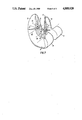
- FIG. 7 illustrates a perspective view of the femur part of FIG. 1.
- the femur part which is to be fixed at the distal end of a femur bone 1 (FIG. 1) is provided with a pair of condyle shells 3.
- each shell 3 is of condyloid form on the exterior and is located to one side of a sagittal plane 2.
- the shells 3 roll off in a sliding manner on a tibia part (not shown) and in so doing essentially transmit the load forces through the knee joint.
- a tangential plane 16 to the vertex of the condyle shells 3 is substantially horizontal.
- a surface normal 4 to the tangential plane 16 at the vertex of the condyle shells 3 is vertical.
- the femur part also has a patella shield 5 which connects the condyle shells together frontally.
- This shield 5 has a rearwardly facing convex surface 6 which, in this example, represents a segment from the outer surface of a hollow cylinder.
- the patella shield 5 In relation to the sagittal plane 2, the patella shield 5 has an asymmetrical form so that the area of the patella shield is greater in the lateral direction, i.e. toward the outside rather than edially (see FIG. 3).
- the femur part illustrated is intended for a left femur bone 1.
- the femur part also has a femoral plateau 8 which connects the patella shield 5 to a backwall 10.
- This backwall 10 connects the dorsal regions 9 of the condyle shells together and has a convex outer surface 11 facing the patella shield 5, which, in this example consists of a segment of a hollow cylinder.
- the backwall 10 stands upright in the direction of the surface normal 4.
- the convex surfaces 6, 11 face each other and are adapted to engage opposite sides of the femur bone 1 as shown in FIG. 1.
- the mutually nearest juxtaposed generatrices of the two convex surfaces 6, 11 form vertex lines 7, 12 which extend so as to lie in a common connecting plane 15 and not in separate intersecting planes.
- the vertex lines 7, 12 define an acute wedge angle which converges distally of 15°.
- the connecting plane 15 is perpendicular to the two tangential planes 18, 19 passing through the vertex lines 7, 12 and coincides with the sagittal plane 2.
- the approximately semi-cylindrical shell of the backwall 10 changes over into a pair of straight vertical sidewalls 13 which merge into the dorsal regions 9 of the condyle shell 3. As indicated in FIG. 1, the sidewalls 13 extend away from the femur bone 1.
- the hollow cylinder creating the patella shield 6 has a considerably greater radius of curvature than the low cylinder of the backwall 10 in this example.
- the hollow cylinder of the backwall 10 in this example The radii of curvature are selected so as to facilitate adaptation of the convex outer surfaces 6, 11 to the form of the femur bone 1 in the respective regions.
- the vertex lines 7, 12 form a wedge angle which may be of a value of up to 30°.
- the wedge angle ⁇ may be in the range of from greater than 0° to 30°.
- the vertex line 12 is in one limit condition in that the vertex line 12 extends parallel to the surface normal 4 whereas the vertex line 7 is inclined.
- the vertex line 7 is parallel to the surface normal 4 while the dorsal vertex line 12 is inclined.
- the bisector of the wedge angle ⁇ forms an angle of ⁇ /2 with the surface normal 4.
- the dorsal regions 9 of the condyle shells 3 have inner surfaces 14 which may abut on the femur bone 1 and which are slightly inclined relative to the surface normal 4.
- the purpose of this inclination is to make unintentional "slipping off" of the femur part from the bone 1 difficult and to make it possible that the condyle shells 3 can be brought forward again relatively far at the top with minimum bone resection.
- a large roll-off region at extreme bending of the knee joint is created.
- the patella shield 5 is given an as asymmetric form relative to the sagittal plane 2 although the vertex line 7 extends in the sagittal plane 2.
- the larger surface area share of the patella shield is thus situated laterally of the sagittal plane 2. This asymmetry has the advantage of achieving an improved approximation as compared to a symmetrical shield, to the physiological facts concerning the patella "sliding" on the shield 5.
- this form is not limited to bodies with circular-cylindrical cross-sections. Instead, elliptical, oval or other cross-sectional forms such as polygonal are also possible. Further, the radii of these cross-sectional shapes may increase in the distal direction so that the generatrices diverge conically as indicated in FIG. 6. However, the vertex lines 7, 12 with the shortest distance a (see FIGS. 2 and 5)always define a common connecting plane 15 which, in the embodiment illustrated in FIGS. 1 to 3, coincides with the sagittal plane 2.
- the common connecting plane 15 and, hence, the vertex lines 7, 12 which primarily bring about the described clamping effect may extend obliquely to the sagittal plane 2. That is, the common connecting plane 15 may be inclined in a lateral or medial direction and/or may be rotated relative to the sagittal plane 2 about the surface normal 4 as an axis of rotation. As indicated, the angle of rotation 8 from the sagittal plane 2 toward each side can amount to from 0° to 20°.
- the connecting plane 15 of the vertex lines 7, 12 may be inclined to the sagittal plane 2 as shown.
- the angle of inclination ⁇ may assume values in the medial direction of up to 5° and in the lateral direction of up to 12°.
- the connecting plane 15 is inclined and rotated simultaneously.
- the invention thus provides a femur part which can be readily clamped to the lower end of a femur bone and held in place in a cement free primary anchoring manner. During an operation, the femur part can be readily slipped onto a femur bone which has been suitable prepared.
Landscapes
- Health & Medical Sciences (AREA)
- Orthopedic Medicine & Surgery (AREA)
- Physical Education & Sports Medicine (AREA)
- Cardiology (AREA)
- Oral & Maxillofacial Surgery (AREA)
- Transplantation (AREA)
- Engineering & Computer Science (AREA)
- Biomedical Technology (AREA)
- Heart & Thoracic Surgery (AREA)
- Vascular Medicine (AREA)
- Life Sciences & Earth Sciences (AREA)
- Animal Behavior & Ethology (AREA)
- General Health & Medical Sciences (AREA)
- Public Health (AREA)
- Veterinary Medicine (AREA)
- Prostheses (AREA)
- Materials For Medical Uses (AREA)
Applications Claiming Priority (2)
| Application Number | Priority Date | Filing Date | Title |
|---|---|---|---|
| CH1595/83 | 1983-03-23 | ||
| CH1595/83A CH657268A5 (de) | 1983-03-23 | 1983-03-23 | Femurteil fuer eine kniegelenkprothese. |
Publications (1)
| Publication Number | Publication Date |
|---|---|
| US4888020A true US4888020A (en) | 1989-12-19 |
Family
ID=4214093
Family Applications (1)
| Application Number | Title | Priority Date | Filing Date |
|---|---|---|---|
| US06/587,950 Expired - Fee Related US4888020A (en) | 1983-03-23 | 1984-03-09 | Femur for a knee joint prosthesis |
Country Status (5)
| Country | Link |
|---|---|
| US (1) | US4888020A (de) |
| EP (1) | EP0119394B1 (de) |
| AT (1) | ATE29961T1 (de) |
| CH (1) | CH657268A5 (de) |
| DE (1) | DE3466475D1 (de) |
Cited By (16)
| Publication number | Priority date | Publication date | Assignee | Title |
|---|---|---|---|---|
| US5133759A (en) * | 1991-05-24 | 1992-07-28 | Turner Richard H | Asymmetrical femoral condye total knee arthroplasty prosthesis |
| WO1998047448A1 (de) * | 1997-04-22 | 1998-10-29 | Plus Endoprothetik Ag | Femurschlitten |
| WO2004069103A1 (de) | 2003-02-05 | 2004-08-19 | Aesculap Ag & Co. Kg | Implantat |
| US20050143836A1 (en) * | 1995-09-04 | 2005-06-30 | Amiram Steinberg | One piece snap fit acetabular cup |
| US7255712B1 (en) | 1997-04-15 | 2007-08-14 | Active Implants Corporation | Bone growth promoting implant |
| US20070260323A1 (en) * | 2005-12-15 | 2007-11-08 | Zimmer, Inc. | Distal femoral knee prostheses |
| US7572295B2 (en) | 2001-12-04 | 2009-08-11 | Active Implants Corporation | Cushion bearing implants for load bearing applications |
| US7758653B2 (en) | 2002-05-23 | 2010-07-20 | Active Implants Corporation | Implants |
| US20130226305A1 (en) * | 2010-09-10 | 2013-08-29 | Zimmer Gmbh | Femoral prosthesis with medialized patellar groove |
| US9301845B2 (en) | 2005-06-15 | 2016-04-05 | P Tech, Llc | Implant for knee replacement |
| US9308095B2 (en) | 2011-06-16 | 2016-04-12 | Zimmer, Inc. | Femoral component for a knee prosthesis with improved articular characteristics |
| WO2016142676A1 (en) * | 2015-03-06 | 2016-09-15 | David Wycliffe Murray | Knee prosthesis |
| US10070966B2 (en) | 2011-06-16 | 2018-09-11 | Zimmer, Inc. | Femoral component for a knee prosthesis with bone compacting ridge |
| US10130375B2 (en) | 2014-07-31 | 2018-11-20 | Zimmer, Inc. | Instruments and methods in performing kinematically-aligned total knee arthroplasty |
| US10136997B2 (en) | 2015-09-29 | 2018-11-27 | Zimmer, Inc. | Tibial prosthesis for tibia with varus resection |
| US10441429B2 (en) | 2011-06-16 | 2019-10-15 | Zimmer, Inc. | Femoral component for a knee prosthesis with improved articular characteristics |
Families Citing this family (3)
| Publication number | Priority date | Publication date | Assignee | Title |
|---|---|---|---|---|
| FR2635679B1 (fr) * | 1988-09-01 | 1994-05-06 | Legroux Philippe | Prothese bicondylienne a glissement pour l'articulation du genou |
| US5203807A (en) * | 1991-07-10 | 1993-04-20 | Smith & Nephew Richards Inc. | Knee joint prosthesis articular surface |
| FR2692475B1 (fr) * | 1992-06-19 | 2000-04-21 | Montpellier Chirurgie | Prothese totale du genou. |
Citations (2)
| Publication number | Priority date | Publication date | Assignee | Title |
|---|---|---|---|---|
| US3798679A (en) * | 1971-07-09 | 1974-03-26 | Ewald Frederick | Joint prostheses |
| US4353135A (en) * | 1980-05-09 | 1982-10-12 | Minnesota Mining And Manufacturing Company | Patellar flange and femoral knee-joint prosthesis |
Family Cites Families (1)
| Publication number | Priority date | Publication date | Assignee | Title |
|---|---|---|---|---|
| GB1448818A (en) * | 1972-09-18 | 1976-09-08 | Nat Res Dev | Prosthetic knee joint devices |
-
1983
- 1983-03-23 CH CH1595/83A patent/CH657268A5/de not_active IP Right Cessation
-
1984
- 1984-01-17 DE DE8484100431T patent/DE3466475D1/de not_active Expired
- 1984-01-17 EP EP84100431A patent/EP0119394B1/de not_active Expired
- 1984-01-17 AT AT84100431T patent/ATE29961T1/de not_active IP Right Cessation
- 1984-03-09 US US06/587,950 patent/US4888020A/en not_active Expired - Fee Related
Patent Citations (2)
| Publication number | Priority date | Publication date | Assignee | Title |
|---|---|---|---|---|
| US3798679A (en) * | 1971-07-09 | 1974-03-26 | Ewald Frederick | Joint prostheses |
| US4353135A (en) * | 1980-05-09 | 1982-10-12 | Minnesota Mining And Manufacturing Company | Patellar flange and femoral knee-joint prosthesis |
Cited By (35)
| Publication number | Priority date | Publication date | Assignee | Title |
|---|---|---|---|---|
| US5133759A (en) * | 1991-05-24 | 1992-07-28 | Turner Richard H | Asymmetrical femoral condye total knee arthroplasty prosthesis |
| US20050143836A1 (en) * | 1995-09-04 | 2005-06-30 | Amiram Steinberg | One piece snap fit acetabular cup |
| US7803193B2 (en) | 1995-09-04 | 2010-09-28 | Active Implants Corporation | Knee prosthesis having a deformable articulation surface |
| US7255712B1 (en) | 1997-04-15 | 2007-08-14 | Active Implants Corporation | Bone growth promoting implant |
| WO1998047448A1 (de) * | 1997-04-22 | 1998-10-29 | Plus Endoprothetik Ag | Femurschlitten |
| US6364911B1 (en) | 1997-04-22 | 2002-04-02 | Plus Endoprothetik Ag | Femoral sled prosthesis |
| US8814946B2 (en) | 2001-12-04 | 2014-08-26 | Active Implants Corporation | Cushion bearing implants for load bearing applications |
| US7572295B2 (en) | 2001-12-04 | 2009-08-11 | Active Implants Corporation | Cushion bearing implants for load bearing applications |
| EP2145604A1 (de) | 2001-12-04 | 2010-01-20 | Active Implants Corporation | Polsterlagerimplantate für lasttragende Anwendungen |
| US7758653B2 (en) | 2002-05-23 | 2010-07-20 | Active Implants Corporation | Implants |
| US20060025865A1 (en) * | 2003-02-05 | 2006-02-02 | Aesculap Ag & Co. Kg | Implant |
| WO2004069103A1 (de) | 2003-02-05 | 2004-08-19 | Aesculap Ag & Co. Kg | Implantat |
| US9301845B2 (en) | 2005-06-15 | 2016-04-05 | P Tech, Llc | Implant for knee replacement |
| US10806590B2 (en) | 2005-06-15 | 2020-10-20 | P Tech, Llc | Methods and systems for providing gender specific pharmaceuticals |
| US9750612B2 (en) | 2005-06-15 | 2017-09-05 | P Tech, Llc | Methods and systems for providing gender specific pharmaceuticals |
| US20070260323A1 (en) * | 2005-12-15 | 2007-11-08 | Zimmer, Inc. | Distal femoral knee prostheses |
| US9592127B2 (en) | 2005-12-15 | 2017-03-14 | Zimmer, Inc. | Distal femoral knee prostheses |
| US10433966B2 (en) | 2005-12-15 | 2019-10-08 | Zimmer, Inc. | Distal femoral knee prostheses |
| US20130226305A1 (en) * | 2010-09-10 | 2013-08-29 | Zimmer Gmbh | Femoral prosthesis with medialized patellar groove |
| US10322004B2 (en) | 2010-09-10 | 2019-06-18 | Zimmer Gmbh | Femoral prosthesis with lateralized patellar groove |
| US9173744B2 (en) * | 2010-09-10 | 2015-11-03 | Zimmer Gmbh | Femoral prosthesis with medialized patellar groove |
| US9867708B2 (en) | 2010-09-10 | 2018-01-16 | Zimmer Gmbh | Femoral prosthesis with lateralized patellar groove |
| US9308095B2 (en) | 2011-06-16 | 2016-04-12 | Zimmer, Inc. | Femoral component for a knee prosthesis with improved articular characteristics |
| US10070966B2 (en) | 2011-06-16 | 2018-09-11 | Zimmer, Inc. | Femoral component for a knee prosthesis with bone compacting ridge |
| US10045850B2 (en) | 2011-06-16 | 2018-08-14 | Zimmer, Inc. | Femoral component for a knee prosthesis with improved articular characteristics |
| US10441429B2 (en) | 2011-06-16 | 2019-10-15 | Zimmer, Inc. | Femoral component for a knee prosthesis with improved articular characteristics |
| US11246710B2 (en) | 2011-06-16 | 2022-02-15 | Zimmer, Inc. | Femoral component for a knee prosthesis with improved articular characteristics |
| US12048630B2 (en) | 2011-06-16 | 2024-07-30 | Zimmer, Inc. | Femoral component for a knee prosthesis with improved articular characteristics |
| US12213889B2 (en) | 2011-06-16 | 2025-02-04 | Zimmer, Inc. | Femoral component for a knee prosthesis with improved articular characteristics |
| US10130375B2 (en) | 2014-07-31 | 2018-11-20 | Zimmer, Inc. | Instruments and methods in performing kinematically-aligned total knee arthroplasty |
| US10939923B2 (en) | 2014-07-31 | 2021-03-09 | Zimmer, Inc. | Instruments and methods in performing kinematically-aligned total knee arthroplasty |
| WO2016142676A1 (en) * | 2015-03-06 | 2016-09-15 | David Wycliffe Murray | Knee prosthesis |
| US10136997B2 (en) | 2015-09-29 | 2018-11-27 | Zimmer, Inc. | Tibial prosthesis for tibia with varus resection |
| US10631991B2 (en) | 2015-09-29 | 2020-04-28 | Zimmer, Inc. | Tibial prosthesis for tibia with varus resection |
| US11491018B2 (en) | 2015-09-29 | 2022-11-08 | Zimmer, Inc. | Tibial prosthesis for tibia with varus resection |
Also Published As
| Publication number | Publication date |
|---|---|
| EP0119394B1 (de) | 1987-09-30 |
| CH657268A5 (de) | 1986-08-29 |
| ATE29961T1 (de) | 1987-10-15 |
| DE3466475D1 (en) | 1987-11-05 |
| EP0119394A1 (de) | 1984-09-26 |
Similar Documents
| Publication | Publication Date | Title |
|---|---|---|
| US4888020A (en) | Femur for a knee joint prosthesis | |
| JP4820547B2 (ja) | 自動整合式膝人工装具 | |
| CA2431096C (en) | Porous unicondylar knee | |
| US4151615A (en) | Prosthetic patello-femoral joint | |
| US6203576B1 (en) | Complete knee joint prosthesis | |
| US4944756A (en) | Prosthetic knee joint with improved patellar component tracking | |
| US4378607A (en) | Elbow replacement prosthesis | |
| EP0955960B1 (de) | Knieendoprothese | |
| US5871545A (en) | Prosthetic knee joint device | |
| US5021061A (en) | Prosthetic patello-femoral joint | |
| US4634444A (en) | Semi-constrained artificial joint | |
| US8480752B2 (en) | Tibial bearing having increased axial-rotation | |
| CA1118154A (en) | Knee joint prosthesis | |
| US4728332A (en) | Artificial menisco-tibial joint | |
| US20030100953A1 (en) | Knee joint prostheses | |
| EP0970667B1 (de) | Drehbare und verschiebbare Gelenkprothese mit hinterer Stabilität | |
| JP3184880B2 (ja) | 人工関節 | |
| US20040220678A1 (en) | Prosthetic device and method for total joint replacement in small joint arthroplasty | |
| DE69528655D1 (en) | Asymmetrische femorale prothese | |
| IE42777B1 (en) | Elbow prosthesis | |
| JPH05168655A (ja) | 体内人工膝関節 | |
| JPH10513371A (ja) | 関節プロテーゼ | |
| CA2924694C (en) | Reverse knee prosthesis | |
| CN114206271A (zh) | 双室膝关节假体 | |
| CA2297551A1 (en) | Femoral component for use in a replacement hip joint |
Legal Events
| Date | Code | Title | Description |
|---|---|---|---|
| AS | Assignment |
Owner name: SULZER BROTHERS LIMITED, WINTHUR, SWITZERLAND, A S Free format text: ASSIGNMENT OF ASSIGNORS INTEREST.;ASSIGNOR:HORBER, WILLI;REEL/FRAME:004263/0256 Effective date: 19840523 Owner name: SULZER BROTHERS LIMITED,SWITZERLAND Free format text: ASSIGNMENT OF ASSIGNORS INTEREST;ASSIGNOR:HORBER, WILLI;REEL/FRAME:004263/0256 Effective date: 19840523 |
|
| CC | Certificate of correction | ||
| REMI | Maintenance fee reminder mailed | ||
| LAPS | Lapse for failure to pay maintenance fees | ||
| FP | Lapsed due to failure to pay maintenance fee |
Effective date: 19931219 |
|
| STCH | Information on status: patent discontinuation |
Free format text: PATENT EXPIRED DUE TO NONPAYMENT OF MAINTENANCE FEES UNDER 37 CFR 1.362 |