US4890589A - Variable capacity type reciprocating piston device - Google Patents
Variable capacity type reciprocating piston device Download PDFInfo
- Publication number
- US4890589A US4890589A US07/244,840 US24484088A US4890589A US 4890589 A US4890589 A US 4890589A US 24484088 A US24484088 A US 24484088A US 4890589 A US4890589 A US 4890589A
- Authority
- US
- United States
- Prior art keywords
- control
- drive
- disc
- piston
- shaft
- Prior art date
- Legal status (The legal status is an assumption and is not a legal conclusion. Google has not performed a legal analysis and makes no representation as to the accuracy of the status listed.)
- Expired - Fee Related
Links
- 230000001360 synchronised effect Effects 0.000 claims description 14
- 238000006073 displacement reaction Methods 0.000 claims description 11
- 239000012530 fluid Substances 0.000 claims description 9
- 238000004891 communication Methods 0.000 claims description 7
- 230000003750 conditioning effect Effects 0.000 claims description 2
- 230000006835 compression Effects 0.000 abstract description 5
- 238000007906 compression Methods 0.000 abstract description 5
- 238000000034 method Methods 0.000 abstract description 2
- 238000002485 combustion reaction Methods 0.000 description 9
- 230000006698 induction Effects 0.000 description 8
- 230000005540 biological transmission Effects 0.000 description 3
- 230000001143 conditioned effect Effects 0.000 description 2
- 238000005086 pumping Methods 0.000 description 2
- 230000015572 biosynthetic process Effects 0.000 description 1
- 239000000567 combustion gas Substances 0.000 description 1
- 230000008878 coupling Effects 0.000 description 1
- 238000010168 coupling process Methods 0.000 description 1
- 238000005859 coupling reaction Methods 0.000 description 1
- 230000007423 decrease Effects 0.000 description 1
- 238000010586 diagram Methods 0.000 description 1
- 230000000694 effects Effects 0.000 description 1
- 239000000446 fuel Substances 0.000 description 1
Images



Classifications
-
- F—MECHANICAL ENGINEERING; LIGHTING; HEATING; WEAPONS; BLASTING
- F16—ENGINEERING ELEMENTS AND UNITS; GENERAL MEASURES FOR PRODUCING AND MAINTAINING EFFECTIVE FUNCTIONING OF MACHINES OR INSTALLATIONS; THERMAL INSULATION IN GENERAL
- F16H—GEARING
- F16H21/00—Gearings comprising primarily only links or levers, with or without slides
- F16H21/10—Gearings comprising primarily only links or levers, with or without slides all movement being in, or parallel to, a single plane
- F16H21/16—Gearings comprising primarily only links or levers, with or without slides all movement being in, or parallel to, a single plane for interconverting rotary motion and reciprocating motion
- F16H21/18—Crank gearings; Eccentric gearings
- F16H21/20—Crank gearings; Eccentric gearings with adjustment of throw
-
- F—MECHANICAL ENGINEERING; LIGHTING; HEATING; WEAPONS; BLASTING
- F01—MACHINES OR ENGINES IN GENERAL; ENGINE PLANTS IN GENERAL; STEAM ENGINES
- F01B—MACHINES OR ENGINES, IN GENERAL OR OF POSITIVE-DISPLACEMENT TYPE, e.g. STEAM ENGINES
- F01B9/00—Reciprocating-piston machines or engines characterised by connections between pistons and main shafts, not specific to groups F01B1/00 - F01B7/00
- F01B9/04—Reciprocating-piston machines or engines characterised by connections between pistons and main shafts, not specific to groups F01B1/00 - F01B7/00 with rotary main shaft other than crankshaft
-
- F—MECHANICAL ENGINEERING; LIGHTING; HEATING; WEAPONS; BLASTING
- F01—MACHINES OR ENGINES IN GENERAL; ENGINE PLANTS IN GENERAL; STEAM ENGINES
- F01B—MACHINES OR ENGINES, IN GENERAL OR OF POSITIVE-DISPLACEMENT TYPE, e.g. STEAM ENGINES
- F01B9/00—Reciprocating-piston machines or engines characterised by connections between pistons and main shafts, not specific to groups F01B1/00 - F01B7/00
- F01B9/04—Reciprocating-piston machines or engines characterised by connections between pistons and main shafts, not specific to groups F01B1/00 - F01B7/00 with rotary main shaft other than crankshaft
- F01B9/047—Reciprocating-piston machines or engines characterised by connections between pistons and main shafts, not specific to groups F01B1/00 - F01B7/00 with rotary main shaft other than crankshaft with rack and pinion
-
- F—MECHANICAL ENGINEERING; LIGHTING; HEATING; WEAPONS; BLASTING
- F01—MACHINES OR ENGINES IN GENERAL; ENGINE PLANTS IN GENERAL; STEAM ENGINES
- F01L—CYCLICALLY OPERATING VALVES FOR MACHINES OR ENGINES
- F01L1/00—Valve-gear or valve arrangements, e.g. lift-valve gear
- F01L1/02—Valve drive
- F01L1/024—Belt drive
-
- F—MECHANICAL ENGINEERING; LIGHTING; HEATING; WEAPONS; BLASTING
- F02—COMBUSTION ENGINES; HOT-GAS OR COMBUSTION-PRODUCT ENGINE PLANTS
- F02B—INTERNAL-COMBUSTION PISTON ENGINES; COMBUSTION ENGINES IN GENERAL
- F02B75/00—Other engines
- F02B75/04—Engines with variable distances between pistons at top dead-centre positions and cylinder heads
- F02B75/048—Engines with variable distances between pistons at top dead-centre positions and cylinder heads by means of a variable crank stroke length
-
- F—MECHANICAL ENGINEERING; LIGHTING; HEATING; WEAPONS; BLASTING
- F02—COMBUSTION ENGINES; HOT-GAS OR COMBUSTION-PRODUCT ENGINE PLANTS
- F02B—INTERNAL-COMBUSTION PISTON ENGINES; COMBUSTION ENGINES IN GENERAL
- F02B2275/00—Other engines, components or details, not provided for in other groups of this subclass
- F02B2275/20—SOHC [Single overhead camshaft]
Definitions
- the present invention relates generally to reciprocating piston type engines and/or compressors and more specifically to a crank arrangement which permits the stroke of a piston to be selective varied in a manner which varies the displacement or capacity of the device.
- each piston is operatively connected with a crankshaft via a connecting rod.
- the work done on the piston by the hot expanding combustion gases is transferred to the crankshaft in a manner which induces the rotation thereof.
- crankshaft is connected to a source of rotational energy (such as a prime mover or the like) either directly or through a clutch and/or a transmission, and the piston is driven to reciprocate and compress and discharge fluid during the compression phase of the same.
- a source of rotational energy such as a prime mover or the like
- the connecting rod is connected to the crankshaft via a crankpin the eccentricity of which is fixed with respect to the axis of rotation of the crankshaft. Accordingly, stroke of the piston is not variably adjustable through the crankshaft connection.
- a further object is to provide an arrangement which can vary the valve train timing and/or ignition timing and the like timing of an engine in response to the change in stroke of the piston or pistons.
- crankshaft of an engine or compressor is arranged to define an Oldham type sliding connection which permits the stroke of a piston or pistons to be selectively varied.
- the axis of the control disc is displaced along a arcuate path the TDC position and compression ratio of the device can be varied.
- Valve train timing can be varied using a belt tensioning technique and can be combined with the stroke control provided by the sliding connection arrangment or arrangements.
- a first aspect of the present invention is deemed to come in the form of a device which features: a first piston, said first piston being reciprocatively disposed in a first cylinder; a first connecting rod, said first connecting rod being connected at a first end thereof to said first piston; a first drive disc, said first drive disc being connected to a first drive shaft for synchronous rotation therewith; means defining a guide slot in said first drive disc which slot extends diametrically across a face of said first drive disc; a first control disc, said first control disc being connected with a first control shaft for synchronous rotation therewith; means defining a guide slot in said first control disc which guide slot extends diametrically across a face of said second disc; a first slider, said first slider being slidably received in the guide slot formed in said first drive disc; a second slider, said second slider being slidably received in the guide slot formed in said first control disc; a first pin, said first pin being operatively connected to a second end of said first connecting rod and fixed
- a further aspect of the invention is deemed to come in the form of the above device wherein said first piston defines a first variable volume chamber in said first cylinder, and which further features: valve means for controlling fluid communication between said first variable volume chamber and a passage associated with said cylinder, said valve means comprising: a cam shaft, said cam shaft having a pulley disposed thereon for synchronous rotation therewith; a drive pulley, said drive pulley being disposed on said first drive shaft for synchronous rotation therewith; a flexible belt operatively interconnecting said drive pulley and the pulley disposed on said cam shaft, said flexible belt including a predetermined amount of slack; guide rollers means for tensioning said belt in a manner which takes up said slack and establishes a drive connection between the two pulleys, said guide roller means being movable and operatively connected to said control device in manner to be displaced with respect to said drive pulley and the pulley disposed on said cam shaft, in a manner which causes the cam shaft to undergo
- Another aspect of the present invention is deemed to comprise an arrangement wherein first, second third and fourth cylinders are arranged in a rectangular configuration and wherein each of the pistons of the four cylinders are connected though sliding connections of the type mentioned above, and which features the arrangement wherein first and second and third and fourth drive shafts are aligned and arranged parallel with one and other; and which further comprises: an input/output shaft which is in drive connection with said first, second, third and fourth drive shafts, the arrangement being such that when said first and third piston assume their TDC positions, said second and fourth piston assume their BDC position.
- a further aspect of the invention is deemed to comprise a device which features: a first piston, said first piston being reciprocatively disposed in a first cylinder in a manner to define a variable volume changer therein; a connecting rod, said connecting rod having a first end operatively connected to said piston and a second end operatively connected with a crankshaft arrangement; valve means for controlling fluid communication between said variable volume chamber and a passage associated with said cylinder, said valve means comprising: a cam shaft, said cam shaft having a pulley fixedly disposed thereon for synchronous rotation therewith; a drive pulley, said drive pulley being fixedly disposed on said first drive shaft for synchronous rotation therewith; a flexible belt operatively interconnecting said drive pulley and the pulley disposed on said cam shaft, said flexible belt including a predetermined amount of slack; guide rollers means for tensioning said belt in a manner which removes said slack, said guide roller means being movable and operatively connected to a control device in
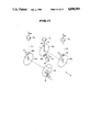
- FIG. 1 is an exploded view showing the constructional features of a first embodiment of the present invention
- FIG. 2 is a diagrammatic sketch showing the basic geometrical configurations produced in accordance with the first embodiment
- FIG. 3 is a diagrammatic sketch showing an embodiment of the present invention as applied to an internal combustion engine wherein the piston stroke is varied in accordance with the induction pressure (load) of the engine;
- FIG. 4 is an exploded view showing the constructional features according to a third embodiment of the present invention.
- FIG. 5 is a schematic diagram showing the characterizing geometrical features which are produced in accordance with the third embodiment
- FIG. 6 is a sectional elevation of an internal combustion chamber of the type wherein the inlet and exhaust valves are operated by a single overhead cam shaft arrangement;
- FIG. 7 is a exploded view showing a valve timing control arrangement which characterizes a fourth embodiment of the present invention.
- FIG. 8 is a schematic elevational view which shows the operation of the fourth embodiment of the present invention.
- FIG. 9 is an exploded view showing a multi-cylinder arrangement according to a sixth embodiment of the present invention.
- FIG. 10 is a schematic elevational view showing the annular momentum and force generation characteristics produced by a single cylinder of the arrangement shown in FIG. 9;
- FIG. 11 is a schematic perspective view showing the balancing concept utilized in the sixth embodiment of the present invention.
- FIGS. 12 and 13 are plan and elevational views showing important relationships developed in connection with the sixth embodiment.
- FIG. 1 shows in exploded view form a first embodiment of the present invention.
- a cylinder block 1 is mounted on top of a main shaft case 2.
- the cylinder block 2 is formed with a cylinder bore (not shown) in which a reciprocal piston 3 is disposed.
- the piston 3 is connected to the upper end of a connecting rod 5 by way of a piston pin 4.
- the lower end of the connecting rod 5 is connected to a connection arrangement generally denoted by the numeral 6, by way of cap 10 and cap bolts 11.
- connection arrangement 6 comprises a short cylindrical shaft portion 7 and two elongate sliders 8 and 9. As shown, the two sliders 8, 9 are fixedly arranged at right angles to each other and are securely connected to the opposite ends of the cylindrical shaft portion 7.
- a first drive disc 12 is formed with a diametrically extending guide slot 15 in the inboard face 13 thereof. As will be appreciated from this figure, this guide slot 15 is arranged to slidably receive slider 8 therein.
- the first drive disc is fixedly connected to the inboard end of a drive shaft 14. This shaft is rotatably supported by a bearing 16 which is connected to the main shaft case 2 by way of bolts 17.
- a second control disc 18 is formed with a diametrically extending guide slot 21 in the inboard face 19 thereof.
- the guide slot 21 is arranged to receive slider 9 therein.
- This second disc 18 is fixedly connected to a coaxial control shaft 20.
- the support shaft is journalled in through bore formed in a reciprocal control slide member 22.
- the reciprocal control member 22 is formed guide grooves 23 in each side thereof. These grooves 23 are arranged to receive the edges of a stationary guide slot 24 formed in the main shaft case 2 in a manner which renders the member 22 slideable in the vertical direction (as seen in the drawings).
- the upper end of the control member 22 is connected with a hydraulic servo unit generally dentoted by the numeral 25.
- This unit 25 comprises a hydraulic cylinder 26 which is secured to an upper section of the main shaft case 2 by way of a connection flange 34.
- a control rod 28 is pivotally connected to the upper end of the control member 22 at its lower end and fixedly connected to a piston 27 at its upper end.
- a control valve unit generally denoted by the numeral 29 is operatively connected with the hydraulic cylinder 26 via conduits 26a and 26b.
- This valve unit 29 comprises a valve body 30 in which a spool 31 is reciprocatively disposed.
- the valve body 30 is formed with an inlet port 35a which is fluidly communicated with a source of hydraulic fluid under pressure (such as an oil pump--not shown).
- the valve body 30 is further formed with two drain ports 35b and 35c proximate the axial ends thereof.
- the spool 31 is formed with two lands 31a and 31b which are arranged to normally locate in a position which block communication between the conduits 26a and 26b and ports 35a, 35b and 35c. Depending on the displacement of the spool 31 from this normal or home position, communication is established between the supply port 35a and one of the conduits 26a and 26b. At the same time the other of the conduits 26a and 26b, is connected with a drain port (viz., one of 35b and 35c). This enables the hydraulic cylinder 26 to be pressurized in a manner which selectively changes the position of the piston 27 therein.
- connection between the piston and the control member 22 is such as to move the latter in the guide slot 24 and thus displace the control disc 18 with respect to the drive disc 12 in a manner which will become more clearly understood hereinlater.
- the lower end of the spool 31 is connected with a control lever 32.
- the control lever 32 is pivotally mounted on a bracket 33 which is fixedly connected with the main shaft case 2 or an associated stationary member.
- the control lever 32 can be (directly) operated manually or can be connected to a suitable control servo as the situation demands. Further disclosure relating to this facet of the present invention will be given hereinlater.
- the arrangement disclosed above is such as to define a so called Oldham type sliding coupling or connection arrangement which can be schematically represented in the manner shown in FIG. 2.
- O1 denotes the axis of rotation of the first drive disc 12 while O2 denotes the axis of rotation of the second control disc 18 and O3 denotes the axis of rotation of the cylindrical shaft portion 7.
- the axis O2 can be displaced with respect to axis O1 in manner which permits the distance L to be selectively adjusted.
- axis O3 is located on the diameters along which the first and second guide slots 15 and 21 extend and therefore in a position which traces a circular path the diameter of which is determined by the displacement L of the axes O1 and O2.
- the axis about which the lower end of the connecting rod 5 is pivotal i.e. axis O3 will trace out the circular path R during reciprocation of the piston 3.
- the diameter of the circular path R changes so does the stroke S of the piston 3.
- FIG. 3 shows a second embodiment of the present invention wherein the manual control, lever arrangement shown in FIG. 1 is replaced with an automatic system which is responsive to the vacuum developed in the induction passage of an internal combustion engine (viz., engine load).
- an internal combustion engine viz., engine load
- a pressure sensor 43 is arranged to sense the pressure prevailing in an induction manifold 42 at location between a throttle valve 42A and an induction port 41.
- the output of the sensor 43 is applied to a control circuit 45 which is arranged to be responsive to the signal in a manner to produce a suitable control signal.
- the control signal is applied to a motor arrangement 44.
- This motor arrangement 44 can take the form of a stepping motor, solenoid, or the like servo (including electrical, hydraulic and pneumatic arrangements) which is connected to the control lever 32'.
- the motor 44 is energized or similarly conditioned to move the spool element 31 in a direction which establishes communication between ports 35a and conduit 26a while establishing communication between port 35c and conduit 26b.
- This embodiment of the invention of course permits automatic control of an engine in response to the load thereon.
- the invention is not limited to the use of induction vacuum to indicate engine load and other suitable parameters can be used as desired.
- the invention is not limited to the use of engine load and other operational parameters such as transmission status, vehicle speed and the like, can be used as deemed appropriate.
- FIG. 4 shows a third embodiment of the present invention.
- This arrangement is basically similar to the arrangement shown in FIG. 1 however features the use of a lever 50 which is pivotally mounted on a pivot pin 51 in place of the sliding control member 22.
- This lever arrangement enables the rotational axis 2 of the control disc 18 to be moved along a curved path instead of a straight vertical one.
- the shaft 20 of the control disc 18 is arranged to project through an arcuate slot 53 and be received in a bore formed in a circular boss 54 located mid-way between a smaller boss 55 formed at one end of the lever 50 and which is formed with a bore which receives the pivot pin 51; and an elongate slot 56 which serves to establish connection between the lever 50 and the lower end of the control rod 28'.
- this enables the system to not only change the length of the piston stroke between a stoke of S1 and S2 but also change the TDC position of the piston (note the distance alpha). Viz., when the stroke is maximized (S1) the piston stops moving upwardly earlier than in the case the stroke is minimized (S2). This of course permits a change in the compression ratio of the system.
- the resulting stroke of the piston S1 is equal to the diameter of circle R1.
- the control disc 18 is moved in a manner which reduces the displacement between the axes O1 and O2, due to the curved path traced out by axis O2 (e.g. O2 moves to O2') the diameter of the circular path traced out by O3 changes from R1 to R2 and is also offset to one side of the cylinder axis M1 in a manner wherein the center of rotation moves from that denoted by O4 to that denoted by O4'. This induces the situation wherein axis O3 with the piston 3 at TDC moves from T1 to T2.
- a variant (fourth embodiment) of the above described embodiment comes in the form of an arrangement wherein angle theta is in fact reduced to zero and the axis of rotation O1 of the drive disc 18 is located on the cylinder axis M1.
- the results produced by this arrangement are essentially identical with those produced by the former one.
- the cam shaft 60 (see FIG. 6) is provided with a pulley 62 which is operatively connected with a pulley 64 mounted on the drive shaft 14, by way of a cogged timing belt 66.
- the timing belt 66 is arranged to have a predetermined amount of slack which is taken up by a pair of guide rollers 68, 70. As shown in FIG.
- these guide rollers or pullies 68, 70 are mounted on a bracket or link 72 by way of stepped shafts 74, 75 which are received in bores formed in the free ends of pivotal levers 76, 78.
- the levers 76, 78 are pivotally mounted on the cam shaft 60 and the drive shaft 14, respectively.
- a connecting bracket 80 is pivotally connected at one end to the center of link 72 and to a bell crank lever 82 at the other.
- the bell crank lever 82 is pivotally mounted on the main shaft case 2 at its elbow section. The other end of the lever is connected to lever 50 through a suitable (non-illustrated) linkage arrangement.
- timing of the valve train can be shifted in a timed relationship with the change in piston stroke.
- the change in timing is not limited to the valve train timing and can be applied to the ignition timing by substituting (and or including) the cam shaft pulley for one connected to the end of the timing shaft of the ignition arrangement.
- FIGS. 9 to 13 show an embodiment of the invention as applied to a multi-cylinder device and which is so arranged as to include an inherent balancing system which neutralizes the vibration which tends to be produced during operation and as the balance of the arrangement changes in accordance with the change in stroke of each piston.
- the numeral 101 denotes a top plate which is secured to a crankcase 102 and which supports an unillustrated cylinder block thereon.
- the crank case 102 is arranged to support two parallel crank shaft arrangements each of which includes two pairs of control and drive discs of the nature described hereinbefore (note that for simplicity of illustration the numerals of these elements have been omitted).
- the control discs are arranged in a back to back configuration in an inboard location while the drive discs are arranged at the outboard ends of the crankshafts.
- the drive shafts of the four drive discs are provided with gears 104 which are arranged to mesh with gears 106 fixed to an input/output shaft 108.
- the so called input/output shaft 108 acts as an input shaft which supplies drive torque to the pistons, while in the case of an internal combustion engine or the like the shaft acts as an output shaft.
- the displacement of the control discs is controlled by a single hydraulic cylinder 110 which is in this instance mounted atop of the top plate 101.
- the cylinder can be formed integrally in the cylinder block if so desired.
- the control rod 112 which depends from the piston 113 reciprocatively disposed in the hydraulic cylinder 110, is connected to a rack 114.
- the rack 114 is formed with an elongate slot therein.
- a sector gear 116 is arranged to mesh with the rack 114 in the illustrated manner.
- This sector gear 116 is pivotally mounted on a bracket 118 which is secured to a mounting bracket 120 forming part of the crankcase 102.
- a linkage 122 operatively interconnects the sector gear 116 with a second pivotal arm 124 which is pivotally supported on a bracket 126. This bracket 126 is secured to a second mounting bracket 128.
- the sector gear 116 and the pivotal arm 124 are provided with bores which receive shafts which each support two control discs (one on each end). With this arrangement when the hydraulic piston 113 is moved, the control discs are synchronously moved in the same direction and thus cause the stroke of each of the four pistons to synchronously change.
- m1-- the mass of the piston, piston pin, connecting rod piston rings and the like
- m0 the rotating mass
- ⁇ denotes the length of the connecting rod while r represents the radius of the circular path R (see FIG. 10) about which the center of mass m0 rotates.
- the inertial force F which is produced by the rotating mass m0 is given by:
- FIG. 11 it will be noted that the instant system is schematically expressed in a manner wherein P1-P4 denote each of the pistons; Cl-C4 denote each of the corresponding connecting rods; M1-M4 denote the corresponding masses of the connection arrangements; and R1-R4 denote the radii about which the masses M1-M4 rotate.
- the forces W2 and W4 are acting upwardly, while the force W1 and W4 are acting the opposite direction. Accordingly, the point Q1 (as seen in plan view) which is located mid-way between each of the cylinders, is such as to be subject to forces which negate one and other.
Landscapes
- Engineering & Computer Science (AREA)
- General Engineering & Computer Science (AREA)
- Mechanical Engineering (AREA)
- Chemical & Material Sciences (AREA)
- Combustion & Propulsion (AREA)
- Compressors, Vaccum Pumps And Other Relevant Systems (AREA)
- Transmission Devices (AREA)
- Output Control And Ontrol Of Special Type Engine (AREA)
Applications Claiming Priority (2)
| Application Number | Priority Date | Filing Date | Title |
|---|---|---|---|
| JP62-234026 | 1987-09-18 | ||
| JP62234026A JPS6477701A (en) | 1987-09-18 | 1987-09-18 | Variable capacity reciprocating piston unit |
Publications (1)
| Publication Number | Publication Date |
|---|---|
| US4890589A true US4890589A (en) | 1990-01-02 |
Family
ID=16964393
Family Applications (1)
| Application Number | Title | Priority Date | Filing Date |
|---|---|---|---|
| US07/244,840 Expired - Fee Related US4890589A (en) | 1987-09-18 | 1988-09-14 | Variable capacity type reciprocating piston device |
Country Status (3)
| Country | Link |
|---|---|
| US (1) | US4890589A (fr) |
| EP (1) | EP0308262A3 (fr) |
| JP (1) | JPS6477701A (fr) |
Cited By (8)
| Publication number | Priority date | Publication date | Assignee | Title |
|---|---|---|---|---|
| GB2257226A (en) * | 1991-07-05 | 1993-01-06 | Pcm Pompes | An adjustable-throw crank mechanism |
| US5184578A (en) * | 1992-03-05 | 1993-02-09 | Borg-Warner Automotive Transmission & Engine Components Corporation | VCT system having robust closed loop control employing dual loop approach having hydraulic pilot stage with a PWM solenoid |
| US5934243A (en) * | 1998-03-26 | 1999-08-10 | Kopystanski; George | Drive mechanism for a reciprocating piston engine |
| US6202623B1 (en) | 1997-09-12 | 2001-03-20 | Preservation Holdings Limited | Internal combustion engines |
| WO2008005131A3 (fr) * | 2006-05-30 | 2008-10-30 | Robert Downs | Transmission à variation continue |
| CN104832281A (zh) * | 2015-01-08 | 2015-08-12 | 武汉富国发动机科技有限公司 | 优化的节能内燃机 |
| US20210372507A1 (en) * | 2017-12-08 | 2021-12-02 | Bes Isletme Arge Ve Muhendislik Cozumleri Sanayi Ticaret Limited Sirketi | Variable displacement mechanism output movement of which can be lowered to zero stroke |
| US11352918B1 (en) * | 2021-02-20 | 2022-06-07 | Anthony John Peila | Variable valve timing method and mechanism |
Families Citing this family (2)
| Publication number | Priority date | Publication date | Assignee | Title |
|---|---|---|---|---|
| JP2530951B2 (ja) * | 1991-08-02 | 1996-09-04 | 米原技研有限会社 | オルダム駆動エンジン |
| JP2003013847A (ja) * | 2001-03-26 | 2003-01-15 | Okinawa General Bureau Cabinet Office | 水力作動コンプレッサ |
Citations (8)
| Publication number | Priority date | Publication date | Assignee | Title |
|---|---|---|---|---|
| US3496918A (en) * | 1968-04-23 | 1970-02-24 | Madison H Finlay | Variable valve timing control for internal combustion engines |
| US3888217A (en) * | 1973-09-24 | 1975-06-10 | Charles A Hisserich | Camshaft belt drive for variable valve timing |
| US4440123A (en) * | 1982-01-28 | 1984-04-03 | General Motors Corporation | Half speed balancer |
| US4480607A (en) * | 1983-08-01 | 1984-11-06 | General Motors Corporation | Balancer for 90 degree V6 engines and the like |
| US4484543A (en) * | 1979-06-20 | 1984-11-27 | Maxey Joel W | Adjustable non-throttling control apparatus for spark ignition internal combustion engines |
| DE3322769A1 (de) * | 1983-06-24 | 1985-01-10 | Daimler-Benz Ag, 7000 Stuttgart | Spannvorrichtung fuer ein umschlingungsgetriebe |
| US4525151A (en) * | 1982-03-08 | 1985-06-25 | Toyota Jidosha Kabushiki Kaisha | Timing adjustment mechanism in wrapping connector driving device |
| US4576127A (en) * | 1984-05-14 | 1986-03-18 | Nissan Motor Co., Ltd. | Valve timing control device for an internal combustion engine |
Family Cites Families (4)
| Publication number | Priority date | Publication date | Assignee | Title |
|---|---|---|---|---|
| US1872856A (en) * | 1929-09-11 | 1932-08-23 | Clinton L Walker | Internal combustion engine |
| CH329490A (de) * | 1954-02-24 | 1958-04-30 | Neukirch Johannes | Exzentergetriebe |
| DE2557811C3 (de) * | 1975-12-22 | 1982-06-09 | BURDOSA Ing. Herwig Burgert, 6305 Buseck | Geradschubkurbeltrieb mit einer als Antrieb dienenden Kreuzscheibenkupplung |
| JPS58213586A (ja) * | 1982-06-04 | 1983-12-12 | Toshiba Corp | 位相合成装置 |
-
1987
- 1987-09-18 JP JP62234026A patent/JPS6477701A/ja active Pending
-
1988
- 1988-09-14 US US07/244,840 patent/US4890589A/en not_active Expired - Fee Related
- 1988-09-16 EP EP19880308619 patent/EP0308262A3/fr not_active Withdrawn
Patent Citations (8)
| Publication number | Priority date | Publication date | Assignee | Title |
|---|---|---|---|---|
| US3496918A (en) * | 1968-04-23 | 1970-02-24 | Madison H Finlay | Variable valve timing control for internal combustion engines |
| US3888217A (en) * | 1973-09-24 | 1975-06-10 | Charles A Hisserich | Camshaft belt drive for variable valve timing |
| US4484543A (en) * | 1979-06-20 | 1984-11-27 | Maxey Joel W | Adjustable non-throttling control apparatus for spark ignition internal combustion engines |
| US4440123A (en) * | 1982-01-28 | 1984-04-03 | General Motors Corporation | Half speed balancer |
| US4525151A (en) * | 1982-03-08 | 1985-06-25 | Toyota Jidosha Kabushiki Kaisha | Timing adjustment mechanism in wrapping connector driving device |
| DE3322769A1 (de) * | 1983-06-24 | 1985-01-10 | Daimler-Benz Ag, 7000 Stuttgart | Spannvorrichtung fuer ein umschlingungsgetriebe |
| US4480607A (en) * | 1983-08-01 | 1984-11-06 | General Motors Corporation | Balancer for 90 degree V6 engines and the like |
| US4576127A (en) * | 1984-05-14 | 1986-03-18 | Nissan Motor Co., Ltd. | Valve timing control device for an internal combustion engine |
Cited By (10)
| Publication number | Priority date | Publication date | Assignee | Title |
|---|---|---|---|---|
| GB2257226A (en) * | 1991-07-05 | 1993-01-06 | Pcm Pompes | An adjustable-throw crank mechanism |
| GB2257226B (en) * | 1991-07-05 | 1995-01-04 | Pcm Pompes | A motion-transmitting device |
| US5184578A (en) * | 1992-03-05 | 1993-02-09 | Borg-Warner Automotive Transmission & Engine Components Corporation | VCT system having robust closed loop control employing dual loop approach having hydraulic pilot stage with a PWM solenoid |
| US6202623B1 (en) | 1997-09-12 | 2001-03-20 | Preservation Holdings Limited | Internal combustion engines |
| US5934243A (en) * | 1998-03-26 | 1999-08-10 | Kopystanski; George | Drive mechanism for a reciprocating piston engine |
| WO2008005131A3 (fr) * | 2006-05-30 | 2008-10-30 | Robert Downs | Transmission à variation continue |
| CN104832281A (zh) * | 2015-01-08 | 2015-08-12 | 武汉富国发动机科技有限公司 | 优化的节能内燃机 |
| WO2016110073A1 (fr) * | 2015-01-08 | 2016-07-14 | 武汉富国发动机科技有限公司 | Moteur à combustion interne |
| US20210372507A1 (en) * | 2017-12-08 | 2021-12-02 | Bes Isletme Arge Ve Muhendislik Cozumleri Sanayi Ticaret Limited Sirketi | Variable displacement mechanism output movement of which can be lowered to zero stroke |
| US11352918B1 (en) * | 2021-02-20 | 2022-06-07 | Anthony John Peila | Variable valve timing method and mechanism |
Also Published As
| Publication number | Publication date |
|---|---|
| JPS6477701A (en) | 1989-03-23 |
| EP0308262A2 (fr) | 1989-03-22 |
| EP0308262A3 (fr) | 1990-11-22 |
Similar Documents
| Publication | Publication Date | Title |
|---|---|---|
| US5025757A (en) | Reciprocating piston engine with a varying compression ratio | |
| US5375567A (en) | Adiabatic, two-stroke cycle engine | |
| US5007385A (en) | Crankless engine | |
| US6460450B1 (en) | Piston engine balancing | |
| US7007589B1 (en) | Piston assembly | |
| EP0708274B1 (fr) | Dispositif a manivelle et dispositif de machine | |
| US7334548B2 (en) | Piston joint | |
| US5507253A (en) | Adiabatic, two-stroke cycle engine having piston-phasing and compression ratio control system | |
| CA1240576A (fr) | Regulateur de phases pour ensembles mecaniques | |
| US5992356A (en) | Opposed piston combustion engine | |
| US5113809A (en) | Axial cylinder internal combustion engine having variable displacement | |
| US4890589A (en) | Variable capacity type reciprocating piston device | |
| US2539880A (en) | Variable stroke engine | |
| US6854377B2 (en) | Variable stroke balancing | |
| US6968751B2 (en) | Axial piston machines | |
| US3921602A (en) | Rotary cylinder internal combustion engine | |
| WO2008010490A1 (fr) | MOTEUR ALTERNATIF cycloïdAL ET POMPE EMPLOYANT CE MÉCANISME DE VILEBREQUIN | |
| US4066049A (en) | Internal combustion engine having a variable engine displacement | |
| KR20190058323A (ko) | 왕복 2-사이클 또는 4-사이클 내연기관의 무한 가변 압축비 및 단일 스트로크 또는 이중 스트로크 길이 기구 | |
| US3198022A (en) | Wobble plate anchor control mechanism | |
| EP1170462B1 (fr) | Machine a piston comprenant un mecanisme sans bielle | |
| US4354459A (en) | Non-throttling control apparatus for spark ignition internal combustion engines | |
| JPH0561485B2 (fr) | ||
| US4907950A (en) | Variable positive fluid displacement system | |
| US4635494A (en) | Infinitely variable transmission and control apparatus therefor |
Legal Events
| Date | Code | Title | Description |
|---|---|---|---|
| AS | Assignment |
Owner name: NISSAN SHATAI COMPANY, LIMITED, 10-1, AMANUMA, HIR Free format text: ASSIGNMENT OF ASSIGNORS INTEREST.;ASSIGNOR:MIYATE, HIROO;REEL/FRAME:004949/0791 Effective date: 19880905 Owner name: NISSAN SHATAI COMPANY, LIMITED, 10-1, AMANUMA, HIR Free format text: ASSIGNMENT OF ASSIGNORS INTEREST;ASSIGNOR:MIYATE, HIROO;REEL/FRAME:004949/0791 Effective date: 19880905 |
|
| FPAY | Fee payment |
Year of fee payment: 4 |
|
| FPAY | Fee payment |
Year of fee payment: 8 |
|
| REMI | Maintenance fee reminder mailed | ||
| LAPS | Lapse for failure to pay maintenance fees | ||
| STCH | Information on status: patent discontinuation |
Free format text: PATENT EXPIRED DUE TO NONPAYMENT OF MAINTENANCE FEES UNDER 37 CFR 1.362 |
|
| FP | Lapsed due to failure to pay maintenance fee |
Effective date: 20020102 |