US4893922A - Measurement system and measurement method - Google Patents
Measurement system and measurement method Download PDFInfo
- Publication number
- US4893922A US4893922A US07/291,377 US29137788A US4893922A US 4893922 A US4893922 A US 4893922A US 29137788 A US29137788 A US 29137788A US 4893922 A US4893922 A US 4893922A
- Authority
- US
- United States
- Prior art keywords
- measurement
- light
- measuring device
- measurement system
- retroreflectors
- Prior art date
- Legal status (The legal status is an assumption and is not a legal conclusion. Google has not performed a legal analysis and makes no representation as to the accuracy of the status listed.)
- Expired - Fee Related
Links
- 238000005259 measurement Methods 0.000 title claims abstract description 48
- 238000000691 measurement method Methods 0.000 title description 3
- 238000003384 imaging method Methods 0.000 claims abstract description 7
- 230000001360 synchronised effect Effects 0.000 claims abstract description 5
- 230000005540 biological transmission Effects 0.000 claims description 7
- 239000011159 matrix material Substances 0.000 claims description 7
- 230000005855 radiation Effects 0.000 claims description 3
- 238000005286 illumination Methods 0.000 claims description 2
- 238000013500 data storage Methods 0.000 claims 2
- 238000000034 method Methods 0.000 description 6
- 230000003292 diminished effect Effects 0.000 description 1
- 238000012432 intermediate storage Methods 0.000 description 1
Images
Classifications
-
- G—PHYSICS
- G01—MEASURING; TESTING
- G01S—RADIO DIRECTION-FINDING; RADIO NAVIGATION; DETERMINING DISTANCE OR VELOCITY BY USE OF RADIO WAVES; LOCATING OR PRESENCE-DETECTING BY USE OF THE REFLECTION OR RERADIATION OF RADIO WAVES; ANALOGOUS ARRANGEMENTS USING OTHER WAVES
- G01S17/00—Systems using the reflection or reradiation of electromagnetic waves other than radio waves, e.g. lidar systems
- G01S17/86—Combinations of lidar systems with systems other than lidar, radar or sonar, e.g. with direction finders
-
- G—PHYSICS
- G01—MEASURING; TESTING
- G01C—MEASURING DISTANCES, LEVELS OR BEARINGS; SURVEYING; NAVIGATION; GYROSCOPIC INSTRUMENTS; PHOTOGRAMMETRY OR VIDEOGRAMMETRY
- G01C15/00—Surveying instruments or accessories not provided for in groups G01C1/00 - G01C13/00
-
- G—PHYSICS
- G01—MEASURING; TESTING
- G01S—RADIO DIRECTION-FINDING; RADIO NAVIGATION; DETERMINING DISTANCE OR VELOCITY BY USE OF RADIO WAVES; LOCATING OR PRESENCE-DETECTING BY USE OF THE REFLECTION OR RERADIATION OF RADIO WAVES; ANALOGOUS ARRANGEMENTS USING OTHER WAVES
- G01S17/00—Systems using the reflection or reradiation of electromagnetic waves other than radio waves, e.g. lidar systems
- G01S17/02—Systems using the reflection of electromagnetic waves other than radio waves
- G01S17/06—Systems determining position data of a target
- G01S17/42—Simultaneous measurement of distance and other co-ordinates
-
- G—PHYSICS
- G01—MEASURING; TESTING
- G01S—RADIO DIRECTION-FINDING; RADIO NAVIGATION; DETERMINING DISTANCE OR VELOCITY BY USE OF RADIO WAVES; LOCATING OR PRESENCE-DETECTING BY USE OF THE REFLECTION OR RERADIATION OF RADIO WAVES; ANALOGOUS ARRANGEMENTS USING OTHER WAVES
- G01S17/00—Systems using the reflection or reradiation of electromagnetic waves other than radio waves, e.g. lidar systems
- G01S17/02—Systems using the reflection of electromagnetic waves other than radio waves
- G01S17/06—Systems determining position data of a target
- G01S17/46—Indirect determination of position data
-
- G—PHYSICS
- G01—MEASURING; TESTING
- G01S—RADIO DIRECTION-FINDING; RADIO NAVIGATION; DETERMINING DISTANCE OR VELOCITY BY USE OF RADIO WAVES; LOCATING OR PRESENCE-DETECTING BY USE OF THE REFLECTION OR RERADIATION OF RADIO WAVES; ANALOGOUS ARRANGEMENTS USING OTHER WAVES
- G01S7/00—Details of systems according to groups G01S13/00, G01S15/00, G01S17/00
- G01S7/48—Details of systems according to groups G01S13/00, G01S15/00, G01S17/00 of systems according to group G01S17/00
- G01S7/481—Constructional features, e.g. arrangements of optical elements
- G01S7/4811—Constructional features, e.g. arrangements of optical elements common to transmitter and receiver
Definitions
- the invention relates to a measurement system for the measurement of an object, and to a corresponding measurement method.
- the object of the invention consists in providing a simple measurement system and measurement method, with which the measurement can be undertaken simply, rapidly and with a very high degree of automation.
- Retroreflectors especially triple mirrors, have the property of reflecting back the light, with a very low degree of scatter, substantially in the direction from which it comes. Accordingly, if the object is illuminated by the light source, then in the vicinity of the light source, with a video camera, even at a large distance of the object the light rays reflected by the retroreflectors can clearly be detected and recorded. The locations of these image points in the image of the video camera can then be determined, which can take place automatically by means of appropriate computers and the like. The measurement can then be undertaken on the basis of the known geometry of the arrangement, e.g. the focal length and other imaging properties of the video camera, the instantaneous orientation of the video camera and the known spacing of the retroreflectors.
- the known geometry of the arrangement e.g. the focal length and other imaging properties of the video camera, the instantaneous orientation of the video camera and the known spacing of the retroreflectors.
- a white light source can be employed as the light source.
- An infrared light source can also be employed, which facilitates, in particular, measurement during the day.
- the light source employed is not a continuous light source, but a light source which emits light flashes, e.g. a flash lamp.
- the light flashes are advantageously synchronized with the scanning frequency of the video camera.
- the image of the retroreflectors is recorded by the camera at unfavourable instants of the scanning cycle.
- synchronization can facilitate the overcoming of the problems which arise, in particular during the day, on account of the fact that the image of the light reflected by the retroreflectors is dominated by the daylight.
- a matrix CCD camera is particularly advantageous, because in this case direct access of the computer to the individual matrix points is possible.
- the measuring device exhibits arrangements for the determination of the distance of the object on the basis of the spacing of the two image points. In this manner, it is possible to carry out a particularly simple determination of the spacing, without complicated transit time measurements, as is the case, for example, with laser range finding measurements. In the course of this procedure, the distance of the object can be determined from the know spacing of the retroreflectors and the imaging geometry.
- the measuring device is provided with arrangements for the determination of the relative velocity of the object.
- the relative velocity If the measuring device itself is fixed, then this relative velocity is equal to the actual velocity of the object. If the measuring device is also moving, then the velocity of the measuring device must be subtracted from the relative velocity, in order to determine the absolute velocity of the object.
- the measuring device is provided with arrangements for the determination of the swing of the object relative to the measuring device.
- the two retroreflectors are not disposed precisely one above the other or beside one another. Indeed, with due consideration being given to this swing, it is then also possible to carry out a better determination of the correct distance. It is, of course, also possible to carry out flange finding without the explicit measurement of swing, by automatically taking account of the swing.
- the measuring device can be fixed. However, if the object moves to a greater extend, then a follow-up adjustment device for the measuring device can be provided, so that the object always remain within the image field, even in the case of a relatively small imaging angle of the measuring device.
- the transmission of information is effected by a narrowly concentrated beam, in particular a laser beam of a microwave beam, or by a data radio transmitter.
- a narrowly concentrated beam in particular a laser beam of a microwave beam, or by a data radio transmitter.
- laser light, microwave radiation or radio waves can be modulated more simply and in an improved manner, as well as with a larger bandwidth than conventional light.
- narrow concentration consists in that unauthorized persons cannot tap into the transmission of information.
- the range finding can be carried out with greater accuracy. This is based on the following findings.
- the video camera e.g.the matrix CCD camera or a line camera
- the video camera has in the vertical direction (and also in the horizontal direction) a limited resolution of, for example, 500 image points or pixels. This leads also to a limited accuracy of range finding, as is illustrated with reference to the following example.
- the object is to have a distance of 1 km, and the retroreflectors at the object are to have a vertical distance of 1 m.
- the imaging geometry is to be such that the images of the two retroreflectors have a spacing of 25 pixels in the television image.
- the image of one reflector if the image of the other reflector is maintained stationary, falls only on the next image point (pixel) when the distance of the object becomes greater or smaller by 40 m. This inaccuracy becomes greater if the object distance becomes greater.
- the two images of the retroreflectors would only have a spacing of 8 pixels. Only if the distance changed by one eighth, i.e. by approximately 375 m, would the image of the retroreflector fall on the next image point, i.e. the corresponding inaccuracy would be greater, that is to say 350 m.
- the measurement can be carried out in a simple manner if the measuring device itself is stationary or executes a known movement. If, however, the measuring device is not stationary and executes a specific movement which is not accurately known, then, advantageously, arrangements are provided for the illumination of a section of the direct environment of the measuring device, as well as arrangements for the imaging of this section by the camera and arrangements for the determination of the specific movement of the measuring device on the basis of changes of the image of the section.
- the appropriate part of the environment which is illuminated by a partial beam and is reflected into the video image, could, for example, be the ground in the environment. If the measuring device moves, then the image section of the ground also moves. From the speed of movement of the grey tones of this image, which speed can be determined electronically, it is then possible to determine the specific movement of the measuring device.
- the invention is also further characterized by a method for the measurement of an object, which method is distinguished in that the object is provided with two retroreflectors disposed at a known spacing from one another and is illuminated by a light source, in that the image of the light reflected by the retroreflectors is recorded by a video camera, and in that the measurement is carried out by analysis of the locations and movements of the image points of the retroreflectors.
- retroreflectors When reference is made here to retroreflectors, these do not in any sense need to be traditional triple mirrors, which have in all cases only a certain aperture angle of at most 60°. Rather, by way of a retroreflector, it is also possible to provide an entire arrangement of such triple mirrors, which are disposed, for example, around a rod, so that the reflecting action occurs in all directions. In this manner, the measurement is also possible in circumstances in which the object, e.g. a rod, rotates about its own axis during the measurement.
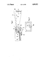
- FIG. 1 shows in schematic representation an embodiment of the measurement system according to the invention.
- FIG. 2 shows the video image which is analyzed in the case of this embodiment.
- the measurement system exhibits a measuring device (1) indicated in broken lines and a target (2), which has, for example, the form of a measuring rod.
- a target (2) which has, for example, the form of a measuring rod.
- Two retroreflectors (3 and 4) or appropriate retroreflectors are provided at the target (2).
- the measuring device (1) exhibits a light source (5), e.g. a flash lamp in the white light range or infrared range, which emits a cone of light (6), which is directed to the target (2).
- a light source (5) e.g. a flash lamp in the white light range or infrared range, which emits a cone of light (6), which is directed to the target (2).
- the flash sequence of the light source (5) is set by an electronic circuit (19), which is synchronized with the line-scanning frequency or image-scanning frequency of a video camera (7), which is advantageously a matrix CCD camera.
- the light reflected by the retroreflectors (3 and 4) is recorded by means of this television camera (7), which, for this purpose, is provided with an objective lens (8), which can also have a variable focal length.
- results are then placed in intermediate storage in an intermediate store (10) and displayed on a display (11) or printed out there.
- the measuring device (1) moves, then this leads to a movement of the grey tones, from which the actual velocity of the measuring device (1) can then be determined with the aid of the circuit (9). This then permits, from the measurement of the relative location and of the relative velocity of the object (2), the determination of the absolute location and the absolute location and the absolute velocity of the object (2).
Landscapes
- Physics & Mathematics (AREA)
- Engineering & Computer Science (AREA)
- Radar, Positioning & Navigation (AREA)
- Remote Sensing (AREA)
- General Physics & Mathematics (AREA)
- Electromagnetism (AREA)
- Computer Networks & Wireless Communication (AREA)
- Length Measuring Devices By Optical Means (AREA)
- Optical Radar Systems And Details Thereof (AREA)
- Numerical Control (AREA)
- Radar Systems Or Details Thereof (AREA)
Applications Claiming Priority (2)
| Application Number | Priority Date | Filing Date | Title |
|---|---|---|---|
| DE19863623083 DE3623083A1 (de) | 1986-07-09 | 1986-07-09 | Vorrichtung zur schusssimulation |
| DE3623083 | 1986-07-09 |
Related Parent Applications (1)
| Application Number | Title | Priority Date | Filing Date |
|---|---|---|---|
| US06935741 Continuation | 1986-11-28 |
Publications (1)
| Publication Number | Publication Date |
|---|---|
| US4893922A true US4893922A (en) | 1990-01-16 |
Family
ID=6304754
Family Applications (1)
| Application Number | Title | Priority Date | Filing Date |
|---|---|---|---|
| US07/291,377 Expired - Fee Related US4893922A (en) | 1986-07-09 | 1988-12-23 | Measurement system and measurement method |
Country Status (4)
| Country | Link |
|---|---|
| US (1) | US4893922A (de) |
| EP (1) | EP0253017B1 (de) |
| AT (1) | ATE56543T1 (de) |
| DE (2) | DE3623083A1 (de) |
Cited By (18)
| Publication number | Priority date | Publication date | Assignee | Title |
|---|---|---|---|---|
| US5200792A (en) * | 1989-08-31 | 1993-04-06 | Nec Corporation | Device for obtaining distance information from an object by instantaneously illuminating the object by a light beam |
| US5394183A (en) * | 1992-05-05 | 1995-02-28 | Milliken Research Corporation | Method and apparatus for entering coordinates into a computer |
| US5458470A (en) * | 1991-05-16 | 1995-10-17 | Sandoz Ltd. | Pumping apparatus |
| US5467634A (en) * | 1993-07-22 | 1995-11-21 | Minnesota Mining And Manufacturing Company | Method and apparatus for calibrating three-dimensional space for machine vision applications |
| US5473931A (en) * | 1993-07-22 | 1995-12-12 | Minnesota Mining And Manufacturing Company | Method and apparatus for calibrating three-dimensional space for machine vision applications |
| US5600760A (en) * | 1984-10-12 | 1997-02-04 | Sensor Adaptive Machines Inc. | Target based determination of robot and sensor alignment |
| WO1998020456A1 (en) * | 1996-11-05 | 1998-05-14 | Primex Technologies, Inc. | Digital imaging and analysis system |
| US5793034A (en) * | 1995-09-18 | 1998-08-11 | Daedalus Enterprises, Inc. | Target detection system utilizing multiple optical criteria |
| US5805287A (en) * | 1993-05-24 | 1998-09-08 | Metronor As | Method and system for geometry measurements |
| US20030164045A1 (en) * | 2002-03-04 | 2003-09-04 | The Regents Of The University Of Michigan | Method and system for measuring vibration of an object |
| US6710799B2 (en) | 2000-12-28 | 2004-03-23 | Umech Technologies | Microscopic motion measuring |
| GB2408326A (en) * | 2003-11-22 | 2005-05-25 | Steven Lee Jones | Modulated-beam optical pointer for position detection system |
| US20050232733A1 (en) * | 2002-09-30 | 2005-10-20 | Siemens Aktiengesellschaft | Method and device for recognition of a load on a lifting gear |
| US20130151040A1 (en) * | 2011-05-21 | 2013-06-13 | Christopher T. Allen | Low-altitude altimeter and method |
| US20160031682A1 (en) * | 2014-07-31 | 2016-02-04 | Par Systems, Inc. | Crane motion control |
| US9443311B2 (en) | 2014-06-12 | 2016-09-13 | Topcon Positioning Systems, Inc. | Method and system to identify a position of a measurement pole |
| US10962363B2 (en) | 2016-01-25 | 2021-03-30 | Topcon Positioning Systems, Inc. | Method and apparatus for single camera optical measurements |
| US11143499B2 (en) * | 2018-09-18 | 2021-10-12 | Electronics And Telecommunications Research Institute | Three-dimensional information generating device and method capable of self-calibration |
Families Citing this family (5)
| Publication number | Priority date | Publication date | Assignee | Title |
|---|---|---|---|---|
| DE3720595A1 (de) * | 1987-04-27 | 1988-11-10 | Precitronic | Verfahren und vorrichtung zur schusssimulation |
| EP0374265B1 (de) * | 1988-06-15 | 1996-09-11 | Japan Industrial Land Development Co., Ltd. | Vermessungsgerät mit automatischer verfolgung |
| DE58908085D1 (de) * | 1989-11-27 | 1994-08-25 | Precitronic | Vorrichtung zum Bestimmen der Ablage eines Ziels von einem bestimmten Ort. |
| KR930007231A (ko) * | 1991-09-13 | 1993-04-22 | 강진구 | 캠코더의 물체추적장치와 그 방법 |
| US5446548A (en) * | 1993-10-08 | 1995-08-29 | Siemens Medical Systems, Inc. | Patient positioning and monitoring system |
Citations (17)
| Publication number | Priority date | Publication date | Assignee | Title |
|---|---|---|---|---|
| US3653769A (en) * | 1970-03-06 | 1972-04-04 | Us Navy | Stadiametric ranging system |
| US3773422A (en) * | 1971-04-07 | 1973-11-20 | Singer Co | Calculating linear dimensions from tv images |
| US3796492A (en) * | 1971-06-01 | 1974-03-12 | Autech Corp | Laser dimension comparator |
| US3917196A (en) * | 1974-02-11 | 1975-11-04 | Boeing Co | Apparatus suitable for use in orienting aircraft flight for refueling or other purposes |
| US4003659A (en) * | 1974-11-15 | 1977-01-18 | The United States Of America As Represented By The Secretary Of The Army | Single plane corner reflector guidance system |
| US4047816A (en) * | 1976-06-18 | 1977-09-13 | The United States Of America As Represented By The Secretary Of The Army | Attitude determination using two transmitter/receiver stations and skewed reflectors |
| US4053233A (en) * | 1976-03-15 | 1977-10-11 | Aerodyne Research, Inc. | Retroreflectors |
| US4136950A (en) * | 1976-11-08 | 1979-01-30 | Labrum Engineering, Inc. | Microscope system for observing moving particles |
| US4297725A (en) * | 1978-08-24 | 1981-10-27 | Agency Of Industrial Science & Technology | Method for measurement of displacement of moving body by use of target mark and apparatus therefor |
| US4355895A (en) * | 1979-07-26 | 1982-10-26 | Coal Industry (Patents) Limited | Survey systems |
| US4373804A (en) * | 1979-04-30 | 1983-02-15 | Diffracto Ltd. | Method and apparatus for electro-optically determining the dimension, location and attitude of objects |
| US4373808A (en) * | 1980-10-20 | 1983-02-15 | The United States Of America As Represented By The Secretary Of The Army | Laser doppler attitude measurement |
| US4391514A (en) * | 1981-02-13 | 1983-07-05 | The United States Of America As Represented By The Administrator Of The National Aeronautics And Space Administration | Sidelooking laser altimeter for a flight simulator |
| US4396945A (en) * | 1981-08-19 | 1983-08-02 | Solid Photography Inc. | Method of sensing the position and orientation of elements in space |
| US4652917A (en) * | 1981-10-28 | 1987-03-24 | Honeywell Inc. | Remote attitude sensor using single camera and spiral patterns |
| US4684247A (en) * | 1985-10-18 | 1987-08-04 | Calspan Corporation | Target member for use in a positioning system |
| US4760269A (en) * | 1986-05-20 | 1988-07-26 | The Mitre Corporation | Method and apparatus for measuring distance to an object |
Family Cites Families (6)
| Publication number | Priority date | Publication date | Assignee | Title |
|---|---|---|---|---|
| FR1454451A (fr) * | 1965-08-04 | 1966-02-11 | Comp Generale Electricite | Dispositif de pointage combiné radar-laser |
| NL159789B (nl) * | 1970-10-29 | 1979-03-15 | Siemens Ag | Optische afstandmeetinrichting. |
| FR2186658B1 (de) * | 1972-03-13 | 1976-10-29 | Thomson Csf | |
| FR2488396A1 (fr) * | 1980-08-07 | 1982-02-12 | Onera (Off Nat Aerospatiale) | Procede et dispositifs optiques pour la determination d'un parametre d'attitude d'un corps |
| US4671654A (en) * | 1983-05-21 | 1987-06-09 | Mac Co., Ltd. | Automatic surveying apparatus using a laser beam |
| DE3601536C1 (de) | 1986-01-20 | 1987-07-02 | Messerschmitt Boelkow Blohm | Anordnung zur Lagebestimmung eines Objektes |
-
1986
- 1986-07-09 DE DE19863623083 patent/DE3623083A1/de not_active Withdrawn
- 1986-10-07 EP EP86113889A patent/EP0253017B1/de not_active Expired - Lifetime
- 1986-10-07 DE DE8686113889T patent/DE3674206D1/de not_active Expired - Lifetime
- 1986-10-07 AT AT86113889T patent/ATE56543T1/de not_active IP Right Cessation
-
1988
- 1988-12-23 US US07/291,377 patent/US4893922A/en not_active Expired - Fee Related
Patent Citations (17)
| Publication number | Priority date | Publication date | Assignee | Title |
|---|---|---|---|---|
| US3653769A (en) * | 1970-03-06 | 1972-04-04 | Us Navy | Stadiametric ranging system |
| US3773422A (en) * | 1971-04-07 | 1973-11-20 | Singer Co | Calculating linear dimensions from tv images |
| US3796492A (en) * | 1971-06-01 | 1974-03-12 | Autech Corp | Laser dimension comparator |
| US3917196A (en) * | 1974-02-11 | 1975-11-04 | Boeing Co | Apparatus suitable for use in orienting aircraft flight for refueling or other purposes |
| US4003659A (en) * | 1974-11-15 | 1977-01-18 | The United States Of America As Represented By The Secretary Of The Army | Single plane corner reflector guidance system |
| US4053233A (en) * | 1976-03-15 | 1977-10-11 | Aerodyne Research, Inc. | Retroreflectors |
| US4047816A (en) * | 1976-06-18 | 1977-09-13 | The United States Of America As Represented By The Secretary Of The Army | Attitude determination using two transmitter/receiver stations and skewed reflectors |
| US4136950A (en) * | 1976-11-08 | 1979-01-30 | Labrum Engineering, Inc. | Microscope system for observing moving particles |
| US4297725A (en) * | 1978-08-24 | 1981-10-27 | Agency Of Industrial Science & Technology | Method for measurement of displacement of moving body by use of target mark and apparatus therefor |
| US4373804A (en) * | 1979-04-30 | 1983-02-15 | Diffracto Ltd. | Method and apparatus for electro-optically determining the dimension, location and attitude of objects |
| US4355895A (en) * | 1979-07-26 | 1982-10-26 | Coal Industry (Patents) Limited | Survey systems |
| US4373808A (en) * | 1980-10-20 | 1983-02-15 | The United States Of America As Represented By The Secretary Of The Army | Laser doppler attitude measurement |
| US4391514A (en) * | 1981-02-13 | 1983-07-05 | The United States Of America As Represented By The Administrator Of The National Aeronautics And Space Administration | Sidelooking laser altimeter for a flight simulator |
| US4396945A (en) * | 1981-08-19 | 1983-08-02 | Solid Photography Inc. | Method of sensing the position and orientation of elements in space |
| US4652917A (en) * | 1981-10-28 | 1987-03-24 | Honeywell Inc. | Remote attitude sensor using single camera and spiral patterns |
| US4684247A (en) * | 1985-10-18 | 1987-08-04 | Calspan Corporation | Target member for use in a positioning system |
| US4760269A (en) * | 1986-05-20 | 1988-07-26 | The Mitre Corporation | Method and apparatus for measuring distance to an object |
Cited By (29)
| Publication number | Priority date | Publication date | Assignee | Title |
|---|---|---|---|---|
| US5706408A (en) * | 1984-10-12 | 1998-01-06 | Sensor Adaptive Machines, Inc. | Target based determination of robot and sensor alignment |
| US5854880A (en) * | 1984-10-12 | 1998-12-29 | Sensor Adaptive Machines, Inc. | Target based determination of robot and sensor alignment |
| US5600760A (en) * | 1984-10-12 | 1997-02-04 | Sensor Adaptive Machines Inc. | Target based determination of robot and sensor alignment |
| US5200792A (en) * | 1989-08-31 | 1993-04-06 | Nec Corporation | Device for obtaining distance information from an object by instantaneously illuminating the object by a light beam |
| US5458470A (en) * | 1991-05-16 | 1995-10-17 | Sandoz Ltd. | Pumping apparatus |
| US5394183A (en) * | 1992-05-05 | 1995-02-28 | Milliken Research Corporation | Method and apparatus for entering coordinates into a computer |
| US5805287A (en) * | 1993-05-24 | 1998-09-08 | Metronor As | Method and system for geometry measurements |
| US5473931A (en) * | 1993-07-22 | 1995-12-12 | Minnesota Mining And Manufacturing Company | Method and apparatus for calibrating three-dimensional space for machine vision applications |
| US5467634A (en) * | 1993-07-22 | 1995-11-21 | Minnesota Mining And Manufacturing Company | Method and apparatus for calibrating three-dimensional space for machine vision applications |
| US5793034A (en) * | 1995-09-18 | 1998-08-11 | Daedalus Enterprises, Inc. | Target detection system utilizing multiple optical criteria |
| WO1998020456A1 (en) * | 1996-11-05 | 1998-05-14 | Primex Technologies, Inc. | Digital imaging and analysis system |
| US5898790A (en) * | 1996-11-05 | 1999-04-27 | Maxwell Technologies, Inc. | Digital imaging and analysis system |
| US6710799B2 (en) | 2000-12-28 | 2004-03-23 | Umech Technologies | Microscopic motion measuring |
| US6792811B2 (en) | 2002-03-04 | 2004-09-21 | The Regents Of The University Of Michigan | Method and system for measuring vibration of an object |
| US20030164045A1 (en) * | 2002-03-04 | 2003-09-04 | The Regents Of The University Of Michigan | Method and system for measuring vibration of an object |
| US20050232733A1 (en) * | 2002-09-30 | 2005-10-20 | Siemens Aktiengesellschaft | Method and device for recognition of a load on a lifting gear |
| US7137771B2 (en) * | 2002-09-30 | 2006-11-21 | Siemens Aktiengesellschaft | Method and device for recognition of a load on a lifting gear |
| GB2408326A (en) * | 2003-11-22 | 2005-05-25 | Steven Lee Jones | Modulated-beam optical pointer for position detection system |
| GB2408326B (en) * | 2003-11-22 | 2006-04-19 | Steven Lee Jones | Pointer position detection |
| US8583296B2 (en) * | 2011-05-21 | 2013-11-12 | University Of Kansas | Low-altitude altimeter and method |
| US20130151040A1 (en) * | 2011-05-21 | 2013-06-13 | Christopher T. Allen | Low-altitude altimeter and method |
| US20140058593A1 (en) * | 2011-05-21 | 2014-02-27 | University Of Kansas | Low-altitude altimeter and method |
| US9008869B2 (en) * | 2011-05-21 | 2015-04-14 | University Of Kansas | Low-altitude altimeter and method |
| US9443311B2 (en) | 2014-06-12 | 2016-09-13 | Topcon Positioning Systems, Inc. | Method and system to identify a position of a measurement pole |
| US20160031682A1 (en) * | 2014-07-31 | 2016-02-04 | Par Systems, Inc. | Crane motion control |
| US9776838B2 (en) * | 2014-07-31 | 2017-10-03 | Par Systems, Inc. | Crane motion control |
| US10962363B2 (en) | 2016-01-25 | 2021-03-30 | Topcon Positioning Systems, Inc. | Method and apparatus for single camera optical measurements |
| US11898875B2 (en) | 2016-01-25 | 2024-02-13 | Topcon Positioning Systems, Inc. | Method and apparatus for single camera optical measurements |
| US11143499B2 (en) * | 2018-09-18 | 2021-10-12 | Electronics And Telecommunications Research Institute | Three-dimensional information generating device and method capable of self-calibration |
Also Published As
| Publication number | Publication date |
|---|---|
| EP0253017B1 (de) | 1990-09-12 |
| EP0253017A2 (de) | 1988-01-20 |
| EP0253017A3 (en) | 1988-03-02 |
| DE3623083A1 (de) | 1988-01-21 |
| DE3674206D1 (de) | 1990-10-18 |
| ATE56543T1 (de) | 1990-09-15 |
Similar Documents
| Publication | Publication Date | Title |
|---|---|---|
| US6137569A (en) | Survey instrument | |
| US6989890B2 (en) | Apparatus for taking up an object space | |
| US10901090B2 (en) | TOF camera system and a method for measuring a distance with the system | |
| US5485009A (en) | Laser imaging system with a linear detector array | |
| US6721679B2 (en) | Distance measuring apparatus and distance measuring method | |
| US7466359B2 (en) | Image-pickup apparatus and method having distance measuring function | |
| Moore et al. | Development of a new underwater bathymetric laser imaging system: L-bath | |
| US3941483A (en) | Target identification apparatus | |
| CA2956784C (en) | Tracking method and tracking system | |
| EP1008831A1 (de) | Universalabstandsmesser | |
| US5889582A (en) | Image-directed active range finding system | |
| CN1253636A (zh) | 远心光阑3维照相机及方法 | |
| JP2000002518A (ja) | 3次元入力装置 | |
| US9939265B2 (en) | Tracking method and tracking system | |
| EP0253017B1 (de) | Vermessungssystem und Vermessungsverfahren | |
| JP3011121B2 (ja) | 警備システム | |
| US4216498A (en) | Visibility monitor employing television camera | |
| JP3991501B2 (ja) | 3次元入力装置 | |
| US7164467B2 (en) | Method and apparatus for electronically generating an outline indicating the size of an energy zone imaged onto the IR detector of a radiometer | |
| US6301371B1 (en) | Object identification system applications | |
| JP3553515B2 (ja) | 高精度測距レーザレーダ装置 | |
| US2941311A (en) | Optical radar simulator | |
| JPH0728166A (ja) | ビデオプロジェクター装置 | |
| Alant’ev et al. | Optical-electronic system for detecting light reflecting objects based on probing by pulsed laser radiation | |
| CN108120990A (zh) | 一种提高距离选通夜视仪测距精度的方法 |
Legal Events
| Date | Code | Title | Description |
|---|---|---|---|
| RR | Request for reexamination filed |
Effective date: 19911007 |
|
| REMI | Maintenance fee reminder mailed | ||
| LAPS | Lapse for failure to pay maintenance fees | ||
| FP | Lapsed due to failure to pay maintenance fee |
Effective date: 19930116 |
|
| STCH | Information on status: patent discontinuation |
Free format text: PATENT EXPIRED DUE TO NONPAYMENT OF MAINTENANCE FEES UNDER 37 CFR 1.362 |