US4896213A - Ghost cancelling reference signal transmission/reception system - Google Patents
Ghost cancelling reference signal transmission/reception system Download PDFInfo
- Publication number
- US4896213A US4896213A US06/885,825 US88582586A US4896213A US 4896213 A US4896213 A US 4896213A US 88582586 A US88582586 A US 88582586A US 4896213 A US4896213 A US 4896213A
- Authority
- US
- United States
- Prior art keywords
- signal
- television signal
- ghost
- digital signal
- transmission
- Prior art date
- Legal status (The legal status is an assumption and is not a legal conclusion. Google has not performed a legal analysis and makes no representation as to the accuracy of the status listed.)
- Expired - Fee Related
Links
Images


Classifications
-
- H—ELECTRICITY
- H04—ELECTRIC COMMUNICATION TECHNIQUE
- H04N—PICTORIAL COMMUNICATION, e.g. TELEVISION
- H04N5/00—Details of television systems
- H04N5/14—Picture signal circuitry for video frequency region
- H04N5/21—Circuitry for suppressing or minimising disturbance, e.g. moiré or halo
-
- H—ELECTRICITY
- H04—ELECTRIC COMMUNICATION TECHNIQUE
- H04N—PICTORIAL COMMUNICATION, e.g. TELEVISION
- H04N5/00—Details of television systems
- H04N5/14—Picture signal circuitry for video frequency region
- H04N5/21—Circuitry for suppressing or minimising disturbance, e.g. moiré or halo
- H04N5/211—Ghost signal cancellation
-
- H—ELECTRICITY
- H04—ELECTRIC COMMUNICATION TECHNIQUE
- H04N—PICTORIAL COMMUNICATION, e.g. TELEVISION
- H04N7/00—Television systems
- H04N7/025—Systems for the transmission of digital non-picture data, e.g. of text during the active part of a television frame
- H04N7/035—Circuits for the digital non-picture data signal, e.g. for slicing of the data signal, for regeneration of the data-clock signal, for error detection or correction of the data signal
Definitions
- the present invention relates to a ghost cancelling reference signal transmission/reception system for transmitting and receiving a ghost cancelling reference signal which is superposed on vertical blanking intervals of a television signal.
- a ghost cancelling device incorporating a transversal filter is known as an effective means for cancelling ghost generated in a transmission path of television signals.
- This device cancels ghost by causing the transversal filter to have a filter characteristic inverse to that of the signal transmission path generating the ghost under the assumption that the signal transmission path functions as a "pseudo-filter".
- the device determines the filter characteristic of the signal transmission path by using a specific reference signal.
- a differential signal of the leading edge of a vertical synchronizing signal is used as this reference signal as shown in "Automatic Cancellation System for Multiple TV ghosts", by S. Onishi and M. Obara, NHK Technical Report, VOL. 21, PP187-191.
- FIGS. 1(a) and 2(b) the above reference signal will be described.
- reference numeral 1 denotes the leading edge of a vertical synchronizing signal
- reference numeral 2 denotes a ghost
- reference numeral 3 denotes a vertical equalizing pulse.
- the ghost 2 is a delayed component of the leading edge 1 of the vertical synchronizing signal.
- FIG. 1(b) shows signal waveforms generated by differentiating the leading edge 1 of the vertical synchronizing signal and the ghost component 2.
- reference numeral 4 denotes the differential signal of the leading edge 1 of the vertical synchronizing signal
- reference numeral 5 denotes the differential signal of the ghost component 2.
- NHK Nippon Housou Kyokai or Japan Broadcast Corporation
- GCR Ghost Cancel Reference
- FIG. 2 The proposed art is represented in FIG. 2, in which reference numeral 6 denotes a bar signal, 7 a pulse signal, 8 a color burst signal and 9 a horizontal synchronizing signal.
- the pulse signal 7 is used for presuming the impulse response of the signal transmission path, and the bar signal 6 is used for detecting an occurrence of a sag generated by the transversal filter.
- the GCR proposed by NHK in order to securely eliminate the ghost, requires the pulse signal 7 to have a specific pulse width as small as about 1.5 T (a half-value width of 187.5 ⁇ sec.) (T : sampling period).
- T sampling period
- the pulse signal is a single pulse, its signal power is very small and thus adversely affected by a noise.
- FIG. 3(a) is a signal waveform showing that a ghost is delayed by more than (1/2)H.
- reference numeral 1 denotes the leading edge of a vertical synchronizing signal
- 3 denotes an equalizing pulse
- 10 denotes a ghost which is a more than (1/2)H delayed equalizing pulse 3.
- reference numeral 4 denotes a differential signal of the leading edge 1 of the vertical synchronizing signal
- reference numeral 11 denotes differential signals of the ghost 10. It cannot be identified from FIGS. 3(a) and 3(b) whether the ghost 10 is derived from the equalizing pulse 3 or the leading edge 1 of the vertical synchronizing signal.
- ghost cancellable range is (1/2)H when the leading edge of the vertical synchronizing signal is used as the reference signal.
- a ghost having a delay time more than 16.8 ⁇ sec. cannot be cancelled even when the GCR proposed by NHK is used.
- An object of the present invention is to eliminate group-delay distortion, frequency-amplitude characteristic distortion, ghost and the like from the television signal transmission system and at the same time allow the system to securely transmit digital data signal.
- the present invention provides a ghost cancelling reference signal transmission/reception system comprising: means for generating a digital signal; means for superposing the digital signal on a television signal in a vertical blanking interval; means for transmitting the television signal containing the superposed digital signal; and ghost-cancelling means for cancelling group-delay distortion, frequency-amplitude characteristic distortion, ghost and the like generated in the television signal transmission means from the television signal transmitted through the transmission means.
- the digital signal is a train of pulses which preferably has a randomness.
- FIGS. 1(a) and 1(b) are waveform charts illustrating a relationship between the leading edge of a vertical synchronizing signal and a ghost;
- FIG. 2 is a waveform chart showing a conventional ghost cancelling reference signal
- FIGS. 3(a) and 3(b) are waveform charts illustrating a relationship between the leading edge of a vertical synchronizing signal and a ghost which has a delay time of more than (1/2)H;
- FIG. 4 is a block diagram showing ghost cancelling reference signal transmission/reception system reflecting a preferred embodiment of the present invention
- FIG. 5 is a block diagram showing an example of digital signal generation circuit
- FIG. 6 is a waveform chart showing an example of digital signal superposed on a horizontal period
- FIG. 7 is a block diagram showing another example of digital signal generation circuit
- FIG. 8 is a block diagram showing an example of data signal extraction circuit
- FIGS. 9 and 10 are block diagrams respectively showing other examples of digital signal generation circuit
- FIG. 11 is a waveform chart showing a pulse signal superposed on a horizontal period
- FIG. 12 is a waveform chart showing a SINX/X signal superposed on a horizontal period
- FIG. 13 is a waveform chart showing a digital-signal and a pulse signal superposed on two horizontal periods
- FIG. 14 is a waveform chart showing a digital-signal and a pulse signal superposed on a horizontal period
- FIG. 15 is a block diagram showing an example of ghost cancelling device
- FIG. 16 is a block diagram showing another example of ghost cancelling device
- FIG. 17 is a block diagram showing an example of circuit incorporating delay circuit and transversal filter
- FIG. 18 is a conceptive chart showing tap co-efficients of transversal filter.
- FIG. 19 is a block diagram showing an example of delay circuit.
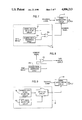
- FIG. 4 shows an embodiment of the ghost cancelling reference signal transmission/reception system of the invention.
- a digital signal generation circuit 15 generates a digital signal composed of a train of pulses.
- the digital signal may be either a coded signal or a random signal.
- the digital signal is used as a ghost cancelling reference signal.
- a signal superposition circuit 12 superposes the digital signal from the digital signal generation circuit 15 on a television signal in a vertical blanking period.
- the digital signal superposed television signal is transmitted through a transmission path 13.
- a ghost cancelling device 14 refers to the digital signal as a reference signal and eliminates group delay distortion, frequency-amplitude characteristic distortion and ghost which are generated in the transmission path 13.
- the transmission path 13 may be either a system which modulates a carrier signal with the television signal and transmits the modulated carrier signal through a radio wave or a wire or cable or a system which records the television signal on a recording medium and reproduces the recorded signal.
- FIG. 5 shows an example of the digital signal generation circuit 15.
- the circuit 15 in FIG. 5 is a known 127-bit length M-series random signal generation circuit, which comprises shift registers (SRs) 16a-16g and an adder 17. Pulses output from the shift registers 16a and 16g are added by the adder 17, and then fed back to the shift register 16a to thereby cause the shift register 16g to output a pseudo random signal as the digital signal.
- SRs shift registers
- the generated digital signal is then delivered to the signal superposition circuit 12, which then superposes the digital signal on the television signal in a vertical blanking period of the television signal.
- the reason for employing the random signal as the digital signal is to make the signal spectrum as flat as possible within the transmission band and also to remove the periodicity of the signal as much as possible.
- FIG. 6 shows an example of waveform of the ghost cancelling reference signal which is superposed on a television signal in a horizontal period in a vertical blanking period of the television signal.
- reference numeral 18 denotes a digital signal or the ghost cancelling reference signal
- 19 denotes a period of superposing the reference signal
- 8 denotes a color burst signal
- 9 denotes horizontal synchronizing signal.
- the digital signal 18 is superposed as a binary NRZ signal in the superposing period 19 in which no vertical synchronizing signal and no vertical equalizing pulse are present.
- the random signal generation circuit is not limited to the circuit in FIG. 5, but other various known random signal generators can be used.
- a data signal generation circuit 20 generates a data signal
- a random signal generation circuit 2a generates a random signal.
- the signals outputted from the data signal generation circuit 20 and the random signal generation circuit 21a are combined by an exclusive OR circuit 22a.
- the combined signal is then superposed as a ghost cancelling reference signal on a television signal by the signal superposition circuit 12.
- the circuit in FIG. 7 can be effectively applied to such a new television system that superposes a specific information on a television signal. Control data required for a television receiver to extract the specific information can be generated by the data signal generation circuit 20 and superposed on the television signal with the circuit in FIG. 7.
- such a system is under development that superposes a high definition signal on a television signal.
- a control signal is required for a television receiver to reproduce the high definition signal.
- the control signal can be superposed on the television signal with the circuit in FIG. 7 by designing the data signal generation circuit 20 so as to generate the control signal.
- such a system is under development that scrambles a television signal at a transmitter and descrambles the scrambled television signal at a receiver.
- a control signal for controlling the receiver can be superposed on the television signal by using the circuit in FIG. 7 at the transmitter.
- the data signal generation circuit 20 can be easily realized by known digital circuit or microcomputer techniques in a variety of manners.
- FIG. 8 shows a data extraction circuit for extracting the data signal from the combined signal containing the data signal and random signal in a television receiver.
- the combined signal is extracted from the received television signal.
- a random signal generation circuit 21b generates the same random signal as that generated by the random signal generation circuit 21a.
- the extracted combined signal and the random signal are applied to an exclusive OR circuit 22b, whereby at the output of the exclusive OR circuit 22b is obtained only the data signal.
- FIG. 9 shows still another example of the digital signal generation circuit 15 which generates a digital signal containing frame synchronizing signals, clock synchronizing signals and data signals following the synchronizing signals, as a ghost cancelling reference signal.
- a synchronizing signal generation circuit 23 generates the frame synchronizing signals and the clock synchronizing signals.
- a data signal generation circuit 150 generates digital data signals.
- a selection circuit 24 selectively passes output signals from the synchronizing signal generation circuit 23 and the data signal generation circuit 150 so as to produce a digital signal having a header part containing the frame synchronizing signals and the clock synchronizing signals, and a data part containing the data signals.
- the digital signal is superposed as a ghost cancelling reference signal on a television signal by the signal superposition circuit 12.
- the circuit in FIG. 9 can be applied to such a system that transmits digital data signals by superposing them on the television signal, such as the teletext system.
- FIG. 10 shows yet another example of the digital signal generation circuit 15.
- a first ghost cancelling reference signal generation circuit 25 generates a digital signal
- a second ghost cancelling reference signal generation circuit 26 generates either a single pulse signal or a sinX/X signal or a fixed signal which will become a bar signal when modulated for transmission.
- FIGS. 11 and 12 respectively show waveforms of the signal pules 70 signal and the sinX/X signal 80.
- a signal switching control circuit 27 alternately selects one of the output signals of the first and second ghost cancelling reference signal generation circuits so that the digital signal and the pulse signal are superposed on a television signal in a way as shown in FIG. 13 or FIG. 14.
- the digital signal 18 serves as a first ghost cancelling reference signal
- the pulse signal 70 serves as a second ghost cancelling reference signal.
- FIG. 13 shows a case in which the first and second ghost cancelling reference signals are separately superposed in two horizontal periods of one field.
- FIG. 14 shows a case in which the first and second ghost cancelling reference signals are superposed in each horizontal period in the vertical blanking period except the periods containing the vertical equalizing pulses and vertical sync pulse.
- the first and second ghost cancelling reference signals are switched every field in FIG. 13, and every half field in FIG. 14. But they may be switched every n fields (n : any integer). In other words, the first reference signal is superposed in consecutive n fields, and the second reference signal is superposed in next consecutive n fields.
- the transmission bit rate of the digital signal should desirably be at least twice the video signal band.
- the transmission bit rate may be twice the color sub-carrier frequency.
- FIG. 15 shows an example of the ghost cancelling device 14 incorporating a transversal filter.
- reference numeral 29 denotes a transversal filter
- 30 denotes a tap-gain correction circuit
- 31 denotes an error signal generation circuit.
- the transversal filter 29 is controlled to have an inverse filter characteristic to the filter characteristic of the transmission path 13 so that the group-delay distortion, frequency-amplitude characteristic distortion and ghost which are produced in the transmission path 13 are eliminated from television signals.
- an output signal from the transversal filter 29 is applied to the error signal generation circuit 31, which then generates an error signal corresponding to a waveform distortion caused by elimination errors of the group-delay distortion, frequency-amplitude characteristic distortion and ghost.
- the tap-gain correction circuit 30 receives the error-signal and the input television signal, and controls the operation of the transversal filter 29 by applying an algorithm such as the mean-square error method to minimize the error signal, i.e., to eliminate the group-delay distortion, frequency-amplitude characteristic distortion and ghost from the television signal.
- an algorithm such as the mean-square error method to minimize the error signal, i.e., to eliminate the group-delay distortion, frequency-amplitude characteristic distortion and ghost from the television signal.
- the error signal generation circuit 31 extracts the digital signal from the output television signal from the transversal filter 29, and obtains a difference between the level of the extracted digital signal and a desired digital signal level. This difference is outputted as the error signal.
- the digital signal Since the digital signal contain a greater amount of power than that of a single pulse, it is more free from an interference of a noise than the conventional single pulse reference signal.
- the correction amount of the tap weight of the transversal filter 29 is obtained by correlative operation between the error signal and the input signal by using the algorithm such as the mean-square error method, even if any potential error caused by a signal other than the reference signal may be present in the error signal, the system operation can securely eliminate adverse influence of the error. Consequently, ghost components having a delay more than a half horizontal period can be eliminated.
- the transversal filter 29 in FIG. 15 may be replaced by any other type of waveform equalizing circuit.
- FIG. 15 can be easily configured by well-known techniques.
- One such example is disclosed in "Ghost Clean System” by J. Murakami et al., IEEE Transactions on Consumer Electronics, VOL. CE-29, No. 3, August 1983, pp. 129-134.
- FIG. 16 shows another example of the ghost cancelling device 14, in which reference numeral 32 denotes an A/D converter, 33 a delay circuit, 34a D/A converter, 35 an input RAM, 36 an output RAM and 37 an operation circuit.
- the A/D converter 32 first quantizes the input television signal.
- the quantized signal is then delivered to the delay circuit 33 to be delayed by a specific time corresponding to a delay time of a ghost having the largest amplitude.
- the operation circuit 37 extracts the ghost cancelling reference signals from the television signals inputted to and outputted from the transversal filter 29, respectively, and then executes an correlative operation between the extracted reference signals.
- the operation circuit 37 controls the transversal filter 29 so that the filter characteristic thereof becomes inverse to that of the transmission path 13, thereby eliminating the group-delay distortion, frequency-amplitude characteristic distortion and ghost. Provision of the delay circuit 33 before the transversal filter 29 allows to securely eliminate those distortions and ghost having a substantial delay amount without enlarging the size of the transversal filter.
- FIG. 17 shows another combination of delay circuit and transversal filter of the ghost cancelling device 14, in which reference numeral 38 denotes a delay element having a delay amount ⁇ o , reference numerals 39 through 42 denote multipliers having coefficients C o through C n , respectively, reference numerals 43 through 46 denotes adders, and reference numerals 47 through 50 denote delay elements each having a delay amount T.
- the tap coefficients in this case becomes as shown in FIG. 18, which shows that the system can effectively eliminate a ghost having any amount of delay by varying the delay amount ⁇ o .
- FIG. 19 shows another example of the delay circuit 33, in which reference numerals 51 and 52 respectively denote first and second RAMs, 53 a RAM switching circuit, 54 an address switching circuit, 55 a read/write control circuit, 57 an address generating circuit, and 58 a delay register.
- the read/write control circuit 55 alternately switches the writing and reading timings of the first and second RAM 51 and 52.
- the delay circuit 33 realizes an arbitrary delay amount by causing the written addresses to delay themselves from the reading addresses by a specific value set by the delay register 58.
- the present invention provides a variety of advantages described below.
- the ghost cancelling reference signal is superposed on a television signal in a vertical blanking period, the reference signal and the video signal are transmitted under the same condition, so that the ghost can be securely eliminated at a receiver.
Landscapes
- Engineering & Computer Science (AREA)
- Multimedia (AREA)
- Signal Processing (AREA)
- Picture Signal Circuits (AREA)
Applications Claiming Priority (4)
| Application Number | Priority Date | Filing Date | Title |
|---|---|---|---|
| JP60-156458 | 1985-07-16 | ||
| JP60156458A JPH0691628B2 (ja) | 1985-07-16 | 1985-07-16 | ゴ−スト除去用基準信号送受信方法 |
| JP60-252152 | 1985-11-11 | ||
| JP60252152A JPH07118781B2 (ja) | 1985-11-11 | 1985-11-11 | ゴースト除去用基準信号送受信方法 |
Publications (1)
| Publication Number | Publication Date |
|---|---|
| US4896213A true US4896213A (en) | 1990-01-23 |
Family
ID=26484201
Family Applications (1)
| Application Number | Title | Priority Date | Filing Date |
|---|---|---|---|
| US06/885,825 Expired - Fee Related US4896213A (en) | 1985-07-16 | 1986-07-15 | Ghost cancelling reference signal transmission/reception system |
Country Status (4)
| Country | Link |
|---|---|
| US (1) | US4896213A (fr) |
| EP (1) | EP0212839B2 (fr) |
| KR (1) | KR900008281B1 (fr) |
| DE (1) | DE3681379D1 (fr) |
Cited By (23)
| Publication number | Priority date | Publication date | Assignee | Title |
|---|---|---|---|---|
| US5065242A (en) * | 1990-06-29 | 1991-11-12 | General Electric Company | Deghosting apparatus using pseudorandom sequences |
| US5065241A (en) * | 1989-08-17 | 1991-11-12 | Kabushiki Kaisha Toshiba | Ghost cancelling system that cancels ghosts from video signals with a transversal filter |
| US5103312A (en) * | 1989-12-29 | 1992-04-07 | Zenith Electronics Corporation | Time variable dispersive filter for minimizing ghost interference |
| DE4226845A1 (de) * | 1991-09-04 | 1993-03-11 | Samsung Electronics Co Ltd | System zum ausloeschen von stoerbildern bei der ntsc-fernsehuebertragung |
| US5260972A (en) * | 1990-03-13 | 1993-11-09 | At&T Bell Laboratories | Technique for determining signal dispersion characteristics in communications systems |
| US5293234A (en) * | 1991-12-11 | 1994-03-08 | Samsung Electronics Co., Ltd. | Ghost cancelling apparatus having transversal filter for generating ghost cancelling signal and method thereof |
| US5325201A (en) * | 1992-12-28 | 1994-06-28 | Sony Electronics Inc. | Pseudo-random number generator based on a video control counter |
| US5353069A (en) * | 1992-05-14 | 1994-10-04 | Matsushita Electric Industrial Co., Ltd | Transmitted television signal waveform equalizing system |
| US5481316A (en) * | 1990-11-05 | 1996-01-02 | Samsung Electronics Co., Ltd. | System, apparatus and method for canceling televison ghost signals |
| US5508814A (en) * | 1991-10-07 | 1996-04-16 | Sony Corporation | Method for transmitting index information in video tape recorder |
| US5600380A (en) * | 1992-12-02 | 1997-02-04 | Samsung Electronics Co., Ltd. | Ghost-cancelation reference signal acquisition circuitry, as for TV receiver or video recorder |
| WO1997013356A1 (fr) * | 1995-10-05 | 1997-04-10 | Philips Electronics N.V. | Detection et synchronisation de signaux de reference d'annulation des images fantômes |
| WO1999055079A1 (fr) * | 1998-04-23 | 1999-10-28 | Intel Corporation | Antidoublement d'image au recepteur hote de donnees teletexte, base sur des donnees non surechantillonnees |
| US6025882A (en) * | 1987-07-27 | 2000-02-15 | Geshwind; David Michael | Methods and devices for incorporating additional information such as HDTV side strips into the blanking intervals of a previous frame |
| CN1051427C (zh) * | 1992-07-23 | 2000-04-12 | 财团法人工业技术研究院 | 电视广播接收系统的多路信号传输方法 |
| US6128337A (en) * | 1997-05-29 | 2000-10-03 | Trimble Navigation Limited | Multipath signal discrimination |
| EP1011266A3 (fr) * | 1998-12-10 | 2000-12-13 | Deutsche Thomson-Brandt Gmbh | Procédé pour la récupération d'un signal vidéo |
| US6184938B1 (en) | 1992-04-22 | 2001-02-06 | Samsung Electronics Co., Ltd. | Ghost cancellation reference signal with bessel chirps & PN sequences, & TV receiver using such signal |
| US6285396B1 (en) * | 1997-08-11 | 2001-09-04 | Nds Limited | Glitch detector |
| US6304299B1 (en) * | 1998-11-30 | 2001-10-16 | General Electric Company | System and method for mitigating multipath effects in television systems |
| US6377308B1 (en) * | 1996-06-26 | 2002-04-23 | Intel Corporation | Method and apparatus for line-specific decoding of VBI scan lines |
| US6437832B1 (en) * | 1999-10-21 | 2002-08-20 | General Electric Company | Mitigation of multipath using ultra wideband DTV overlay signal |
| US20070055099A1 (en) * | 2004-05-10 | 2007-03-08 | Olympus Corporation | Transmitting apparatus, receiving apparatus, and body-insertable apparatus system |
Families Citing this family (5)
| Publication number | Priority date | Publication date | Assignee | Title |
|---|---|---|---|---|
| FR2627340B1 (fr) * | 1988-02-11 | 1991-10-31 | France Etat | Procede de diffusion de programme de television a haute definition et recepteur a egaliseur destine a recevoir un tel programme |
| JP2594639B2 (ja) * | 1989-03-23 | 1997-03-26 | 株式会社日立製作所 | テレビジョン映像受信信号波形歪み検出方法並びにそれに使用するテレビジョン映像信号送信装置および受信装置 |
| US4980767A (en) * | 1989-11-30 | 1990-12-25 | At&T Bell Laboratories | Technique for determining signal dispersion characteristics in communications systems |
| DE69022715T2 (de) * | 1990-03-13 | 1996-05-23 | At & T Corp | Ermittlung von Dispersionseigenschaften eines Fernmelde-Übertragungskanals aus einer empfangenen Prüfsequenz nach Korrelation und Vervielfältigung. |
| US5406586A (en) * | 1991-07-09 | 1995-04-11 | At&T Corp. | Signal correlation technique |
Citations (10)
| Publication number | Priority date | Publication date | Assignee | Title |
|---|---|---|---|---|
| US2236134A (en) * | 1952-10-17 | 1941-03-25 | Int Standard Electric Corp | System of transmission of electric signals |
| GB1370535A (en) * | 1973-05-09 | 1974-10-16 | British Broadcasting Corp | Transmission of alphanumeric data by television |
| US3996419A (en) * | 1975-05-27 | 1976-12-07 | Westinghouse Electric Corporation | Technique for minimizing multi-path distortion effects in video transmission |
| US4047013A (en) * | 1975-07-09 | 1977-09-06 | International Business Machines Corporation | Method and apparatus for fast determination of initial transversal equalizer coefficient values |
| US4176317A (en) * | 1976-03-26 | 1979-11-27 | Siemens Aktiengesellschaft | Circuit arrangement for determining the frequency dependent amplitude fluctuation characteristic of a communications transmission link |
| US4303895A (en) * | 1979-02-14 | 1981-12-01 | Nippon Hoso Kyokai | Automatic equalizer |
| US4321686A (en) * | 1980-01-24 | 1982-03-23 | Communications Satellite Corporation | Correction processor of self-adaptive filters |
| US4367489A (en) * | 1980-08-14 | 1983-01-04 | Rca Corporation | Television ghost detection and cancellation system controlled over several lines of a vertical retrace interval |
| US4435823A (en) * | 1980-12-29 | 1984-03-06 | Harris Corporation | Adaptive equalizer capable of linear and nonlinear weighting |
| US4459613A (en) * | 1979-07-16 | 1984-07-10 | Faroudja Y C | Method and apparatus for automatic adjustment with pilot signal of television image processing system |
-
1986
- 1986-07-14 EP EP86305413A patent/EP0212839B2/fr not_active Expired - Lifetime
- 1986-07-14 DE DE8686305413T patent/DE3681379D1/de not_active Expired - Lifetime
- 1986-07-15 US US06/885,825 patent/US4896213A/en not_active Expired - Fee Related
- 1986-07-16 KR KR1019860005781A patent/KR900008281B1/ko not_active Expired
Patent Citations (10)
| Publication number | Priority date | Publication date | Assignee | Title |
|---|---|---|---|---|
| US2236134A (en) * | 1952-10-17 | 1941-03-25 | Int Standard Electric Corp | System of transmission of electric signals |
| GB1370535A (en) * | 1973-05-09 | 1974-10-16 | British Broadcasting Corp | Transmission of alphanumeric data by television |
| US3996419A (en) * | 1975-05-27 | 1976-12-07 | Westinghouse Electric Corporation | Technique for minimizing multi-path distortion effects in video transmission |
| US4047013A (en) * | 1975-07-09 | 1977-09-06 | International Business Machines Corporation | Method and apparatus for fast determination of initial transversal equalizer coefficient values |
| US4176317A (en) * | 1976-03-26 | 1979-11-27 | Siemens Aktiengesellschaft | Circuit arrangement for determining the frequency dependent amplitude fluctuation characteristic of a communications transmission link |
| US4303895A (en) * | 1979-02-14 | 1981-12-01 | Nippon Hoso Kyokai | Automatic equalizer |
| US4459613A (en) * | 1979-07-16 | 1984-07-10 | Faroudja Y C | Method and apparatus for automatic adjustment with pilot signal of television image processing system |
| US4321686A (en) * | 1980-01-24 | 1982-03-23 | Communications Satellite Corporation | Correction processor of self-adaptive filters |
| US4367489A (en) * | 1980-08-14 | 1983-01-04 | Rca Corporation | Television ghost detection and cancellation system controlled over several lines of a vertical retrace interval |
| US4435823A (en) * | 1980-12-29 | 1984-03-06 | Harris Corporation | Adaptive equalizer capable of linear and nonlinear weighting |
Non-Patent Citations (16)
| Title |
|---|
| "A Study of Reference Signal for Transversal-type Ghost Canceller" by M. Obara, Transactions of the Institute of Electronics and Communication Engineers of Japan, vol. J68-B, No. 12, Dec. 1985, pp. 1381-1389. |
| "Automatic Cancellation System for Multiple TV Ghosts", by S. Onishi and M. Obara, NHK Technical Report, vol. 21, pp. 187-191. |
| "Ghost Cancel Reference Signal" by M. Obara et al., Technical Report of the Institute of Television Engineers of Japan RE81-6, Feb. 1981, pp. 33-38. |
| A Study of Reference Signal for Transversal type Ghost Canceller by M. Obara, Transactions of the Institute of Electronics and Communication Engineers of Japan, vol. J68 B, No. 12, Dec. 1985, pp. 1381 1389. * |
| Automatic Cancellation System for Multiple TV Ghosts , by S. Onishi and M. Obara, NHK Technical Report, vol. 21, pp. 187 191. * |
| Ciciora et al., "A Tutorial on Ghost Cancelling in Television Systems", IEEE Transactions on Consumer Electronics, vol. CE-25, 2/79, pp. 9-43. |
| Ciciora et al., A Tutorial on Ghost Cancelling in Television Systems , IEEE Transactions on Consumer Electronics, vol. CE 25, 2/79, pp. 9 43. * |
| Ghost Cancel Reference Signal by M. Obara et al., Technical Report of the Institute of Television Engineers of Japan RE81 6, Feb. 1981, pp. 33 38. * |
| Hiroshima et al., "Teletext Receiver" IEEE Transactions on Consumer Electronics, vol. CE-26, No. 3, 8/80, pp. 657-663. |
| Hiroshima et al., Teletext Receiver IEEE Transactions on Consumer Electronics, vol. CE 26, No. 3, 8/80, pp. 657 663. * |
| IEEE Transactions on Consumer Electronics, "Ghost Clean System", by Junzo Murakami et al., Toshiba Corporation, vol. CE-29, No. 3, Aug. 1983, pp. 129-134. |
| IEEE Transactions on Consumer Electronics, Ghost Clean System , by Junzo Murakami et al., Toshiba Corporation, vol. CE 29, No. 3, Aug. 1983, pp. 129 134. * |
| Kegel, "Multi-scribosony" Delft Progress Report Series B, vol. 1, No. 2, pp. 36-38, 7/75. |
| Kegel, Multi scribosony Delft Progress Report Series B, vol. 1, No. 2, pp. 36 38, 7/75. * |
| Thedick, "Adaptive Multipath Equalization for T.V. Broadcasting" IEEE Transactions on Consumer Electronics, vol. CE-23, No. 2, 5/77, pp. 175-181. |
| Thedick, Adaptive Multipath Equalization for T.V. Broadcasting IEEE Transactions on Consumer Electronics, vol. CE 23, No. 2, 5/77, pp. 175 181. * |
Cited By (35)
| Publication number | Priority date | Publication date | Assignee | Title |
|---|---|---|---|---|
| US6025882A (en) * | 1987-07-27 | 2000-02-15 | Geshwind; David Michael | Methods and devices for incorporating additional information such as HDTV side strips into the blanking intervals of a previous frame |
| US5065241A (en) * | 1989-08-17 | 1991-11-12 | Kabushiki Kaisha Toshiba | Ghost cancelling system that cancels ghosts from video signals with a transversal filter |
| US5103312A (en) * | 1989-12-29 | 1992-04-07 | Zenith Electronics Corporation | Time variable dispersive filter for minimizing ghost interference |
| US5260972A (en) * | 1990-03-13 | 1993-11-09 | At&T Bell Laboratories | Technique for determining signal dispersion characteristics in communications systems |
| US5065242A (en) * | 1990-06-29 | 1991-11-12 | General Electric Company | Deghosting apparatus using pseudorandom sequences |
| TR25299A (tr) * | 1990-06-29 | 1993-01-01 | Gen Electric | Sinyal distorsiyonunun alinmasi. |
| WO1992000646A1 (fr) * | 1990-06-29 | 1992-01-09 | General Electric Company | Elimination de la distorsion de signaux |
| US5481316A (en) * | 1990-11-05 | 1996-01-02 | Samsung Electronics Co., Ltd. | System, apparatus and method for canceling televison ghost signals |
| DE4226845A1 (de) * | 1991-09-04 | 1993-03-11 | Samsung Electronics Co Ltd | System zum ausloeschen von stoerbildern bei der ntsc-fernsehuebertragung |
| GB2259629A (en) * | 1991-09-04 | 1993-03-17 | Samsung Electronics Co Ltd | Ghost cancellation |
| US5341177A (en) * | 1991-09-04 | 1994-08-23 | Samsung Electronics Co., Ltd | System to cancel ghosts generated by multipath transmission of television signals |
| US5361102A (en) * | 1991-09-04 | 1994-11-01 | Samsung Electronics Co., Ltd. | System to cancel ghosts in NTSC television transmission |
| GB2259629B (en) * | 1991-09-04 | 1995-05-24 | Samsung Electronics Co Ltd | Ghost cancellation |
| US5508814A (en) * | 1991-10-07 | 1996-04-16 | Sony Corporation | Method for transmitting index information in video tape recorder |
| US5293234A (en) * | 1991-12-11 | 1994-03-08 | Samsung Electronics Co., Ltd. | Ghost cancelling apparatus having transversal filter for generating ghost cancelling signal and method thereof |
| US6184938B1 (en) | 1992-04-22 | 2001-02-06 | Samsung Electronics Co., Ltd. | Ghost cancellation reference signal with bessel chirps & PN sequences, & TV receiver using such signal |
| US6937292B1 (en) | 1992-04-22 | 2005-08-30 | Samsung Electronics Co., Ltd. | Ghost cancellation reference signal with bessel chirps and PN sequences, and TV receiver using such signal |
| US20050140828A1 (en) * | 1992-04-22 | 2005-06-30 | Samsung Electronics Co. Ltd. | Ghost cancellation reference signal with bessel chirps and PN sequences, and TV receiver using such signal |
| US6873371B2 (en) * | 1992-04-22 | 2005-03-29 | Samsung Electronics Co., Ltd. | Ghost cancellation reference signal with bessel chirps and PN sequences, and TV receiver using such signal |
| US6480239B1 (en) | 1992-04-22 | 2002-11-12 | Samsung Electronics Co., Ltd. | Ghost cancellation reference signal with bessel chirps and PN sequences, and TV receiver using such signal |
| US5353069A (en) * | 1992-05-14 | 1994-10-04 | Matsushita Electric Industrial Co., Ltd | Transmitted television signal waveform equalizing system |
| CN1051427C (zh) * | 1992-07-23 | 2000-04-12 | 财团法人工业技术研究院 | 电视广播接收系统的多路信号传输方法 |
| US5600380A (en) * | 1992-12-02 | 1997-02-04 | Samsung Electronics Co., Ltd. | Ghost-cancelation reference signal acquisition circuitry, as for TV receiver or video recorder |
| US5325201A (en) * | 1992-12-28 | 1994-06-28 | Sony Electronics Inc. | Pseudo-random number generator based on a video control counter |
| WO1997013356A1 (fr) * | 1995-10-05 | 1997-04-10 | Philips Electronics N.V. | Detection et synchronisation de signaux de reference d'annulation des images fantômes |
| US6377308B1 (en) * | 1996-06-26 | 2002-04-23 | Intel Corporation | Method and apparatus for line-specific decoding of VBI scan lines |
| US6128337A (en) * | 1997-05-29 | 2000-10-03 | Trimble Navigation Limited | Multipath signal discrimination |
| US6285396B1 (en) * | 1997-08-11 | 2001-09-04 | Nds Limited | Glitch detector |
| US6067122A (en) * | 1998-04-23 | 2000-05-23 | Intel Corporation | Host-based anti-ghosting of teletext data based on non-oversampled data |
| WO1999055079A1 (fr) * | 1998-04-23 | 1999-10-28 | Intel Corporation | Antidoublement d'image au recepteur hote de donnees teletexte, base sur des donnees non surechantillonnees |
| US6304299B1 (en) * | 1998-11-30 | 2001-10-16 | General Electric Company | System and method for mitigating multipath effects in television systems |
| EP1011266A3 (fr) * | 1998-12-10 | 2000-12-13 | Deutsche Thomson-Brandt Gmbh | Procédé pour la récupération d'un signal vidéo |
| US6437832B1 (en) * | 1999-10-21 | 2002-08-20 | General Electric Company | Mitigation of multipath using ultra wideband DTV overlay signal |
| US20070055099A1 (en) * | 2004-05-10 | 2007-03-08 | Olympus Corporation | Transmitting apparatus, receiving apparatus, and body-insertable apparatus system |
| US7931585B2 (en) * | 2004-05-10 | 2011-04-26 | Olympus Corporation | Transmitting apparatus, receiving apparatus, and body-insertable apparatus system |
Also Published As
| Publication number | Publication date |
|---|---|
| EP0212839B2 (fr) | 1994-10-19 |
| DE3681379D1 (de) | 1991-10-17 |
| KR870001733A (ko) | 1987-03-17 |
| KR900008281B1 (ko) | 1990-11-10 |
| EP0212839A1 (fr) | 1987-03-04 |
| EP0212839B1 (fr) | 1991-09-11 |
Similar Documents
| Publication | Publication Date | Title |
|---|---|---|
| US4896213A (en) | Ghost cancelling reference signal transmission/reception system | |
| US5481316A (en) | System, apparatus and method for canceling televison ghost signals | |
| US5341177A (en) | System to cancel ghosts generated by multipath transmission of television signals | |
| JP3094387B2 (ja) | Tv受信機あるいはビデオレコーダに使用されるゴースト消去基準信号捕捉回路 | |
| KR0145307B1 (ko) | 고스트 제거회로 | |
| KR0153610B1 (ko) | 영상 캐리어와 직각 위상을 이루는 캐리어를 변조한 신호에서의 고스트 억압 장치 | |
| KR0162611B1 (ko) | Ntsc tv 신호에 실린 디지털 데이타를 복구하기 위한 디지털 신호 수신기에 있어서 기호 클럭 재생 회로 | |
| US4404600A (en) | Ghost signal cancelling apparatus | |
| KR0164053B1 (ko) | 영상신호처리장치의 고스트제거회로를 구동하기 위한 방법 | |
| EP0221684B1 (fr) | Système de réduction du bruit d'un signal vidéo | |
| EP0466434A2 (fr) | Unité de filtrage à égalisation de forme d'onde | |
| KR0169617B1 (ko) | 텔레비젼 수신기 전단과 고스트 억압 회로를 가지는 비디오 테이프 레코더 | |
| US5210607A (en) | Ghost reduction device for removing ghost components of a television signal | |
| US5309226A (en) | Means for cancelling ghost signals in response to the reception of a non-standard television video signal | |
| JP2537798B2 (ja) | ゴ−スト除去用基準信号発生回路 | |
| JP2562721B2 (ja) | 波形等化装置 | |
| JP2537799B2 (ja) | ゴ−スト除去用基準信号発生回路 | |
| JPS6218174A (ja) | ゴ−スト除去用基準信号送受信方法 | |
| KR950001506B1 (ko) | 자동 위상 등화 장치 | |
| JPS62111578A (ja) | ゴ−スト除去用基準信号送受信方法 | |
| JPH0797834B2 (ja) | ゴ−スト除去用基準信号発生装置 | |
| JPH0438196B2 (fr) | ||
| JPS62265869A (ja) | ゴ−スト除去用基準信号発生回路 | |
| JPH05284531A (ja) | 波形等化システム | |
| Gardiner | Echo cancelling |
Legal Events
| Date | Code | Title | Description |
|---|---|---|---|
| AS | Assignment |
Owner name: MATSUSHITA ELECTRIC INDUSTRIAL CO., LTD., 1006, KA Free format text: ASSIGNMENT OF ASSIGNORS INTEREST.;ASSIGNORS:KOBO, KAZUO;FUKUI, KIYOTAKE;NOZOE, TOSHIRO;AND OTHERS;REEL/FRAME:004578/0659 Effective date: 19860702 |
|
| FEPP | Fee payment procedure |
Free format text: PAYOR NUMBER ASSIGNED (ORIGINAL EVENT CODE: ASPN); ENTITY STATUS OF PATENT OWNER: LARGE ENTITY |
|
| FPAY | Fee payment |
Year of fee payment: 4 |
|
| FPAY | Fee payment |
Year of fee payment: 8 |
|
| REMI | Maintenance fee reminder mailed | ||
| LAPS | Lapse for failure to pay maintenance fees | ||
| STCH | Information on status: patent discontinuation |
Free format text: PATENT EXPIRED DUE TO NONPAYMENT OF MAINTENANCE FEES UNDER 37 CFR 1.362 |
|
| FP | Lapsed due to failure to pay maintenance fee |
Effective date: 20020123 |