US4899983A - Anti-wedging pressure seal ring apparatus - Google Patents
Anti-wedging pressure seal ring apparatus Download PDFInfo
- Publication number
- US4899983A US4899983A US07/298,443 US29844389A US4899983A US 4899983 A US4899983 A US 4899983A US 29844389 A US29844389 A US 29844389A US 4899983 A US4899983 A US 4899983A
- Authority
- US
- United States
- Prior art keywords
- seal ring
- pressure seal
- groove
- valve plug
- wall
- Prior art date
- Legal status (The legal status is an assumption and is not a legal conclusion. Google has not performed a legal analysis and makes no representation as to the accuracy of the status listed.)
- Expired - Lifetime
Links
Images
Classifications
-
- F—MECHANICAL ENGINEERING; LIGHTING; HEATING; WEAPONS; BLASTING
- F01—MACHINES OR ENGINES IN GENERAL; ENGINE PLANTS IN GENERAL; STEAM ENGINES
- F01D—NON-POSITIVE DISPLACEMENT MACHINES OR ENGINES, e.g. STEAM TURBINES
- F01D17/00—Regulating or controlling by varying flow
- F01D17/10—Final actuators
-
- F—MECHANICAL ENGINEERING; LIGHTING; HEATING; WEAPONS; BLASTING
- F16—ENGINEERING ELEMENTS AND UNITS; GENERAL MEASURES FOR PRODUCING AND MAINTAINING EFFECTIVE FUNCTIONING OF MACHINES OR INSTALLATIONS; THERMAL INSULATION IN GENERAL
- F16J—PISTONS; CYLINDERS; SEALINGS
- F16J9/00—Piston-rings, e.g. non-metallic piston-rings, seats therefor; Ring sealings of similar construction
- F16J9/12—Details
- F16J9/22—Rings for preventing wear of grooves or like seatings
Definitions
- the present invention relates to an improvement in steam turbines and especially to a pressure seal ring anti-wedging relief groove in a throttling valve.
- Electric utility power generating systems generally comprise an alternating current electric power generator driven by a turbine. While some systems employ water turbines, most systems utilize steam turbines in which a controlled steam flow through the turbine regulates the rotational velocity of a driven turbine shaft. The steam flow is controlled, in response to electric power demands placed on the generator, such that the frequency of the alternating current produced by the generator is maintained at a constant value regardless of variations in electric power demands placed on the generator. The steam flow in turn is controlled by various flow control valves such as throttling valves and steam bypass valves.
- the present invention relates to an improvement in the flow control valves of a steam turbine and especially to a throttling valve.
- these valves had a valve plug riding in a bonnet cylinder with the valve plug having one or more pressure seal ring grooves therein.
- a pressure seal ring can maintain the pressure drop across the ring which results in the pressure seal ring contacting the valve plug.
- the pressure seal ring wears a step in the contact surface along the edge of pressure seal ring groove of the valve plug.
- the resultant step worn along the edge of the groove can result in a wedging of the pressure seal ring between the valve plug and the bonnet cylinder bore and the resultant inability of the valve to close as required for turbine overspeed protection.
- the aim of the present invention is to prevent this wedging of the pressure seal ring between the valve plug and the bonnet cylinder bore as the pressure seal wears into the groove wall of the valve plug.
- a valve plug has a valve plug housing shaped to fit in a bonnet cylinder of a steam control valve of a steam turbine.
- the valve plug has one or more pressure seal ring grooves for holding pressure seal rings therein.
- Each pressure seal ring groove in turn is formed of a pair of annular walls and a bottom surface.
- a relief groove is formed in one wall of the pressure seal ring groove adjacent the bottom surface thereof so that that relief groove will reduce the wedging of the pressure seal ring between the valve plug and the bonnet cylinder bore as the groove wall wears away a step during usage of the valve plug with the pressure seal ring therein.
- the relief groove has a pair of sidewalls and a bottom surface and one side wall forms an extension to the pressure seal ring groove bottom surface so that wear on one pressure seal ring groove wall enlarges the width of the pressure seal groove without forming a step and eliminates the wedging of a pressure seal ring therein.
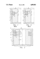
- FIGS. 1 and 2 a portion of a steam turbine steam control valve or bonnet valve 10 in accordance with the prior art is illustrated.
- This prior art configuration includes a valve plug 11, which is similar to a piston, riding in a bonnet cylinder bore 12 of a bonnet cylinder 13.
- Pressure ring 14 rides in a groove 15 and slides against the contact surface 17 formed between the one side of the ring 14 and the bonnet cylinder bore wall 12.
- the pressure in the annular area P1 is the high pressure side and has a higher pressure than the other side P2 of the seal ring 14.
- the application of this pressure differential drives the seal ring 14 against the wall 18 of the groove 15.
- the groove 15 also has a bottom 20 and a wall 21.
- the pressure differential between P1 and P2 as the valve plug 11 moves back and forth keeps the pressure on the surface 18 of the groove 15.
- the ring 14 tends to bind between the side of the step 23 of the valve plug and the bonnet cylinder bore wall 12 anywhere along the outside diameter 24 of the ring 30.
- the resultant step 22 can result in the wedging of the pressure seal as shown and the inability of the valve to close as required for turbine overspeed protection.
- a portion of a valve has a valve plug 26 riding in a bonnet cylinder 27 in the bonnet cylinder bore 28 similar to the embodiment in FIG. 1 and having a valve seal ring 30 riding in a ring groove 31 having a bottom 32 and a wall 33.
- the groove 31 has a wall 34 where the resulting wear can be expected between the ring 30 and the wall 34.
- a relief groove 35 is located adjacent the bottom 32 of the groove 31 and has a bottom 36, a wall 37, and a second wall 38. The wall 38 tends to form a continuous extension from the bottom wall 32 of the groove 31.
- the groove 35 is also an annular relief groove adjacent the annular ring groove 31.
- the groove 31 is enlarged by the wearing away of the wall and no step 22, as shown in FIG. 2, is formed in the improvement of FIG. 3 since the relief groove allows the entire wall 34 to wear away enlarging the groove 31.
- Relief groove wear at least to the depth of the relief groove, can be tolerated without the associated possibility of wedging in accordance with FIG. 2.
Landscapes
- Engineering & Computer Science (AREA)
- General Engineering & Computer Science (AREA)
- Mechanical Engineering (AREA)
- Lift Valve (AREA)
- Control Of Turbines (AREA)
Priority Applications (6)
| Application Number | Priority Date | Filing Date | Title |
|---|---|---|---|
| US07/298,443 US4899983A (en) | 1989-01-18 | 1989-01-18 | Anti-wedging pressure seal ring apparatus |
| KR1019900000540A KR0153111B1 (ko) | 1989-01-18 | 1990-01-17 | 반-쐐기 박기 압축 밀폐 링 장치 |
| CN90100246A CN1035279C (zh) | 1989-01-18 | 1990-01-17 | 抗楔压力密封环装置 |
| ES9000121A ES2020095A6 (es) | 1989-01-18 | 1990-01-17 | Aparato anticunamiento de anillo estanco a la presion. |
| CA002007930A CA2007930C (fr) | 1989-01-18 | 1990-01-17 | Dispositif antiuicoincement pour bague d'etancheite |
| JP2009485A JPH02227501A (ja) | 1989-01-18 | 1990-01-18 | 圧力シールリング装置 |
Applications Claiming Priority (1)
| Application Number | Priority Date | Filing Date | Title |
|---|---|---|---|
| US07/298,443 US4899983A (en) | 1989-01-18 | 1989-01-18 | Anti-wedging pressure seal ring apparatus |
Publications (1)
| Publication Number | Publication Date |
|---|---|
| US4899983A true US4899983A (en) | 1990-02-13 |
Family
ID=23150540
Family Applications (1)
| Application Number | Title | Priority Date | Filing Date |
|---|---|---|---|
| US07/298,443 Expired - Lifetime US4899983A (en) | 1989-01-18 | 1989-01-18 | Anti-wedging pressure seal ring apparatus |
Country Status (6)
| Country | Link |
|---|---|
| US (1) | US4899983A (fr) |
| JP (1) | JPH02227501A (fr) |
| KR (1) | KR0153111B1 (fr) |
| CN (1) | CN1035279C (fr) |
| CA (1) | CA2007930C (fr) |
| ES (1) | ES2020095A6 (fr) |
Cited By (1)
| Publication number | Priority date | Publication date | Assignee | Title |
|---|---|---|---|---|
| EP0447695A1 (fr) * | 1990-03-08 | 1991-09-25 | METAL WORK S.p.A. | Soupape de réglage pression |
Citations (10)
| Publication number | Priority date | Publication date | Assignee | Title |
|---|---|---|---|---|
| DE287694C (fr) * | ||||
| US1963725A (en) * | 1933-09-08 | 1934-06-19 | Perfect Circle Co | Piston and piston ring |
| DE731496C (de) * | 1940-10-22 | 1943-02-10 | Felix Wankel | Stossstellenausbildung fuer Kolbenringe mit winkelfoermigem Querschnitt |
| US3554564A (en) * | 1968-06-12 | 1971-01-12 | Outboard Marine Corp | Pressure backed piston rings |
| US3602261A (en) * | 1969-03-27 | 1971-08-31 | Westinghouse Electric Corp | Stream turbine control valve structure |
| US3831952A (en) * | 1967-02-17 | 1974-08-27 | Sealfire | Piston and piston rings unit for an internal combustion engine |
| US3857542A (en) * | 1972-06-06 | 1974-12-31 | Westinghouse Electric Corp | Noise suppressing throttle valve |
| US4350352A (en) * | 1981-07-24 | 1982-09-21 | Mack Trucks, Inc. | Piston ring and groove assemblies |
| DE3207810A1 (de) * | 1981-03-07 | 1982-09-23 | Shoichi Tokyo Furuhama | Zusammengesetzter kolbenring |
| US4679769A (en) * | 1984-07-27 | 1987-07-14 | Westinghouse Electric Corp. | Steam turbine control valve for cyclic duty |
-
1989
- 1989-01-18 US US07/298,443 patent/US4899983A/en not_active Expired - Lifetime
-
1990
- 1990-01-17 CA CA002007930A patent/CA2007930C/fr not_active Expired - Lifetime
- 1990-01-17 KR KR1019900000540A patent/KR0153111B1/ko not_active Expired - Lifetime
- 1990-01-17 CN CN90100246A patent/CN1035279C/zh not_active Expired - Fee Related
- 1990-01-17 ES ES9000121A patent/ES2020095A6/es not_active Expired - Lifetime
- 1990-01-18 JP JP2009485A patent/JPH02227501A/ja active Pending
Patent Citations (10)
| Publication number | Priority date | Publication date | Assignee | Title |
|---|---|---|---|---|
| DE287694C (fr) * | ||||
| US1963725A (en) * | 1933-09-08 | 1934-06-19 | Perfect Circle Co | Piston and piston ring |
| DE731496C (de) * | 1940-10-22 | 1943-02-10 | Felix Wankel | Stossstellenausbildung fuer Kolbenringe mit winkelfoermigem Querschnitt |
| US3831952A (en) * | 1967-02-17 | 1974-08-27 | Sealfire | Piston and piston rings unit for an internal combustion engine |
| US3554564A (en) * | 1968-06-12 | 1971-01-12 | Outboard Marine Corp | Pressure backed piston rings |
| US3602261A (en) * | 1969-03-27 | 1971-08-31 | Westinghouse Electric Corp | Stream turbine control valve structure |
| US3857542A (en) * | 1972-06-06 | 1974-12-31 | Westinghouse Electric Corp | Noise suppressing throttle valve |
| DE3207810A1 (de) * | 1981-03-07 | 1982-09-23 | Shoichi Tokyo Furuhama | Zusammengesetzter kolbenring |
| US4350352A (en) * | 1981-07-24 | 1982-09-21 | Mack Trucks, Inc. | Piston ring and groove assemblies |
| US4679769A (en) * | 1984-07-27 | 1987-07-14 | Westinghouse Electric Corp. | Steam turbine control valve for cyclic duty |
Cited By (1)
| Publication number | Priority date | Publication date | Assignee | Title |
|---|---|---|---|---|
| EP0447695A1 (fr) * | 1990-03-08 | 1991-09-25 | METAL WORK S.p.A. | Soupape de réglage pression |
Also Published As
| Publication number | Publication date |
|---|---|
| JPH02227501A (ja) | 1990-09-10 |
| CN1035279C (zh) | 1997-06-25 |
| KR0153111B1 (ko) | 1998-11-16 |
| CN1045629A (zh) | 1990-09-26 |
| CA2007930A1 (fr) | 1990-07-18 |
| ES2020095A6 (es) | 1991-07-16 |
| CA2007930C (fr) | 2000-07-18 |
| KR900012026A (ko) | 1990-08-02 |
Similar Documents
| Publication | Publication Date | Title |
|---|---|---|
| EP0595437B1 (fr) | Garniture mécanique d'étanchéité | |
| US5133563A (en) | Two ring piston with lower tapered L-shaped ring | |
| JPH07504485A (ja) | パッキングセグメント重量荷重を消去する重力スプリングを有する流体タービン用の引込み式セグメントパッキングリング | |
| US1689735A (en) | Labyrinth gland construction | |
| US5083536A (en) | Compression piston ring groove for an internal combustion engine | |
| US4048975A (en) | Pistons | |
| US4978102A (en) | Aligning and seal ring retracting apparatus for plug type valve | |
| EP0371407A3 (fr) | Compresseur d'air équipé d'une soupape annulaire | |
| US2466389A (en) | Seal fob fluid pressure motor vanes | |
| US1862983A (en) | Piston ring | |
| US4899983A (en) | Anti-wedging pressure seal ring apparatus | |
| GB2134604A (en) | Rotatable shaft seals | |
| HK34093A (en) | Rotary compressors having backflow preventing valves | |
| US7134856B2 (en) | Compressed air motor | |
| US4202526A (en) | Valve | |
| GB2407626A (en) | Suspended seal arrangement | |
| JP4160398B2 (ja) | 往復機関 | |
| GB1493225A (en) | Seals for rotors of rotary fluid-machines | |
| WO1988000289A1 (fr) | Segment de piston | |
| US2844422A (en) | Piston ring | |
| US1741436A (en) | Hollow packing ring for pistons | |
| US4931001A (en) | Apex seal with filled aperture | |
| US2249255A (en) | Reinforced piston ring | |
| US953627A (en) | Piston packing-ring. | |
| KR200166943Y1 (ko) | 피스톤의 피스톤링 결합구조 |
Legal Events
| Date | Code | Title | Description |
|---|---|---|---|
| AS | Assignment |
Owner name: WESTINGHOUSE ELECTRIC CORPORATION, PENNSYLVANIA Free format text: ASSIGNMENT OF ASSIGNORS INTEREST.;ASSIGNORS:BERRONG, DAVID B.;SCHUCHART, THOMAS L.;REEL/FRAME:005028/0212 Effective date: 19890103 |
|
| STCF | Information on status: patent grant |
Free format text: PATENTED CASE |
|
| FPAY | Fee payment |
Year of fee payment: 4 |
|
| FPAY | Fee payment |
Year of fee payment: 8 |
|
| AS | Assignment |
Owner name: SIEMENS WESTINGHOUSE POWER CORPORATION, FLORIDA Free format text: ASSIGNMENT NUNC PRO TUNC EFFECTIVE AUGUST 19, 1998;ASSIGNOR:CBS CORPORATION, FORMERLY KNOWN AS WESTINGHOUSE ELECTRIC CORPORATION;REEL/FRAME:009605/0650 Effective date: 19980929 |
|
| FEPP | Fee payment procedure |
Free format text: PAYOR NUMBER ASSIGNED (ORIGINAL EVENT CODE: ASPN); ENTITY STATUS OF PATENT OWNER: LARGE ENTITY |
|
| FPAY | Fee payment |
Year of fee payment: 12 |
|
| AS | Assignment |
Owner name: SIEMENS POWER GENERATION, INC., FLORIDA Free format text: CHANGE OF NAME;ASSIGNOR:SIEMENS WESTINGHOUSE POWER CORPORATION;REEL/FRAME:016996/0491 Effective date: 20050801 |