US4900008A - Sheet clamping arrangement for rotatable drums - Google Patents
Sheet clamping arrangement for rotatable drums Download PDFInfo
- Publication number
- US4900008A US4900008A US07/034,665 US3466587A US4900008A US 4900008 A US4900008 A US 4900008A US 3466587 A US3466587 A US 3466587A US 4900008 A US4900008 A US 4900008A
- Authority
- US
- United States
- Prior art keywords
- drum
- shaft
- sheet
- clamping bar
- rotation
- Prior art date
- Legal status (The legal status is an assumption and is not a legal conclusion. Google has not performed a legal analysis and makes no representation as to the accuracy of the status listed.)
- Expired - Lifetime
Links
Images


Classifications
-
- B—PERFORMING OPERATIONS; TRANSPORTING
- B65—CONVEYING; PACKING; STORING; HANDLING THIN OR FILAMENTARY MATERIAL
- B65H—HANDLING THIN OR FILAMENTARY MATERIAL, e.g. SHEETS, WEBS, CABLES
- B65H5/00—Feeding articles separated from piles; Feeding articles to machines
- B65H5/08—Feeding articles separated from piles; Feeding articles to machines by grippers, e.g. suction grippers
- B65H5/12—Revolving grippers, e.g. mounted on arms, frames or cylinders
-
- B—PERFORMING OPERATIONS; TRANSPORTING
- B41—PRINTING; LINING MACHINES; TYPEWRITERS; STAMPS
- B41J—TYPEWRITERS; SELECTIVE PRINTING MECHANISMS, i.e. MECHANISMS PRINTING OTHERWISE THAN FROM A FORME; CORRECTION OF TYPOGRAPHICAL ERRORS
- B41J13/00—Devices or arrangements of selective printing mechanisms, e.g. ink-jet printers or thermal printers, specially adapted for supporting or handling copy material in short lengths, e.g. sheets
- B41J13/10—Sheet holders, retainers, movable guides, or stationary guides
- B41J13/22—Clamps or grippers
- B41J13/223—Clamps or grippers on rotatable drums
Definitions
- This invention relates to sheet handling drums and, more particularly, it concerns an unique sheet clamping arrangement by which the leading and trailing edges of a sheet fed from a supply tray or stack are clamped to a drum for the performance of a printing operation, for example, delivered from the drum to a delivery tray or stack, and the drum and clamping arrangement repositioned to receive another sheet.
- the prior art relating to rotatable sheet handling drums and clamp-like retention devices for holding a sheet on a drum is highly developed in machinery involving a transfer of some media to or from the drum retained sheet.
- the drum retained sheet may control transfer of ink to a succession of receiver sheets whereas in various recording machinery, the drum retained sheet receives ink or its equivalent from a stylus or other writing device.
- the support of the receiving sheet by the drum permits accurate angular registration of the sheet with respect to a writing device usually supported by a carriage for movement axially of the drum.
- U.S. Pat. Nos. 4,033,575 and 4,259,695 contain disclosures of clamping apparatus for retaining a sheet about the periphery of a rotatable drum and by which the leading and trailing edges of the sheet are successively clamped by independently movable clamping bars.
- the leading edge of a sheet fed tangentially to the drum is first seized by a leading edge clamping bar rotatable at all times with the drum. While the trailing edge clamp is held against movement, the drum and the leading edge clamp draw the sheet past the trailing edge clamp until the trailing edge of the sheet registers with the latter clamp. The trailing edge clamp is then closed on the sheet and rotates with the drum during a sheet processing cycle.
- drum sheet clamping arrangements shown in the aforementioned patents are desirable from the standpoint of providing a firm clamping action at opposite ends of a sheet, of enabling the clamping action to occur during drum rotation in one direction, and of avoiding any need for folding, creasing or otherwise mutilating the sheet.
- the mechanisms required for operation of the clamping apparatus disclosed in these patents are complicated and tend to restrict use of the apparatus to relatively slow-speed facsimile machines.
- the disclosed clamping apparatus does not operate by itself to discharge the sheet from the drum.
- drum sheet clamping apparatus heretofore disclosed in order to adapt rotatable drum sheet supports to machinery such as computer driven printers to and from which successive print receiving sheets are fed and discharged automatically.
- an improved sheet clamping system for rotatable drums by which the leading edge of each of a succession of sheets fed to the drum periphery is engaged and clamped in position by a leading edge clamp rotatable at all times with the drum, the sheet is drawn past a trailing edge clamp capable of retention in a fixed position during drum rotation, the trailing edge of the sheet is engaged by the trailing edge clamp for continued rotation of the drum for a printing operation, for example, the sheet is discharged from the drum by the trailing edge clamp, and the drum and both clamps indexed to receive another sheet.
- the system features a cam actuating mechanism for moving each of the clamps between sheet clamping a sheet releasing positions, which cam mechanism requires a minimal number of components and which may be operated by the same motor used to rotate the drum, or alternatively, by a motor dedicated to sheet loading and unloading operations where very high speed printing operation and close drum indexing tolerances require a separate motor for driving and indexing the drum during printing.
- the invention is embodied in a structural organization including a drum and a pair of end caps supported for rotation independently on a common central shaft journalled for rotation in spaced end supports and driven by a reversible electric stepping motor.
- a pair of clamping bars extend axially of the drum at the periphery thereof and are supported respectively by pairs of brackets, one such pair being rotatable at all time with the drum whereas the other such bracket pair is rotatable at all times with the end caps.
- the one of the two clamping bars functioning as the leading edge clamp is supported from the brackets connected for rotation with the drum.
- the trailing edge clamp is retained at its ends by brackets supported from the end caps.
- a cam set is mounted on the central supporting shaft.
- Each cam set cooperates with internal cam tracks on the respective brackets and circumscribing the axis of the central shaft.
- the cam sets and cooperating cam tracks or equivalent function to move the clamping bars from a clamping position against the drum periphery to a retracted position spaced from the drum periphery.
- the common central supporting shaft is driven by a single reversible electric stepping motor both during the sheet loading and unloading operation and during rotational movement of the drum with a mounted sheet during a printing operation, for example.
- the drum is coupled to the shaft by a one-way clutch so that the drum rotates directly with the shaft during one direction of shaft rotation but may be held stationary upon rotation of the shaft in the reverse direction.
- the drum is coupled directly to the shaft for rotation at all times therewith and the shaft driven during printing operations by one motor which is designed for use only during printing operations.
- a second relatively low speed reversible stepping motor is provided for driving the drum during sheet loading and unloading operations.
- the latter motor is coupled to the drum supporting shaft by gearing including a one-way clutch so that operation of the drum and end caps, as well as the cooperation between the clamp retaining brackets and the cam sets, remain substantially unchanged from the first mentioned embodiment.
- a principal object of the present invention is therefore the provision of a sheet handling drum and clamping system by which individual sheets may be fed to the drum from a supply stack, clamped to the drum and ultimately delivered by actuation of the clamping system to a receiving stack.
- Another object of the invention is to provide such a drum and sheet clamping system which requires a minimal number of parts for effective operation.
- Still another object of the present invention is the provision of an improved cam actuating system by which a pair of clamping bars may be operated with respect to the periphery of a drum to retain and eject a sheet therefrom.
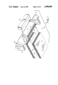
- FIG. 1 is a partially exploded perspective view illustrating in somewhat schematic form the principal components of a printer incorporating the present invention and as seen from the bottom right;
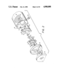
- FIG. 2 is an exploded perspective view illustrating the assembly of components at one end of a sheet retaining drum incorporating one embodiment of the clamping system of the present invention
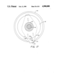
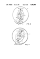
- FIG. 3 is an end elevation in partial cross section illustrating one end of a sheet supporting drum incorporating the invention
- FIG. 4 is an end elevation in partial cross section through an end cap of the invention and showing the superimposition of brackets, one of which is shown in FIG. 3;
- FIGS. 5-8 inclusively, are schematic illustrations representing respective phases of sheet handling and clamping operations using the clamping system of the present invention.
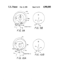
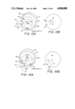
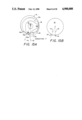
- FIGS. 9A-15A are schematic illustrations of the cam actuating system of the present invention in various operating conditions
- FIGS. 9B-15B are schematic illustrations corresponding to the illustrations of FIGS. 9A-15A but showing the position of clamping bars at the respective cam positions illustrated in FIGS. 9A-15A;
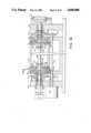
- FIG. 16 is a cross section illustrating the several components of another embodiment of the present invention.
- FIG. 17 is an enlarged cross section on line 11--11 of FIG. 10.
- the reference numeral 20 generally designates a printer including a print head assembly 22, a sheet retaining drum 24 supported by a central shaft 26 journalled by bearings 27 in axially spaced supports 28 and 30, and a drive motor 32 carried by the support 30.
- a supply stack 34 of sheets to be printed is shown positioned under a delivery stack 36 of the same sheets after printing. Obviously the stacks 34 and 36 will be supported in trays or the equivalent of trays which are not shown in the interest of clarity.
- the drum is shown to be positioned between a pair of end caps 38 and 40 supported by the shaft 26 to be coaxial with the drum 24 but rotatable independently of the drum 24 on the shaft 26.
- the drum 24 is provided with a pair of axial slots 42 and 44 in its cylindrical surface.
- a leading edge clamping bar 46 is positioned at the radial plane of the slot 42 whereas a trailing edge clamping bar 48 is similarly positioned at the radial plane of the slot 44.
- the bars 46 and 48 are parts of a sheet clamping system by which a sheet fed from the supply stack 34 may be clamped at its leading and trailing edges about the periphery of the drum 24.
- FIG. 2 of the drawings components positioned between one end face 50 of the drum 24 and the end cap 38 in one embodiment of the invention are illustrated in exploded perspective as spaced along the axis of the shaft 26.
- the components shown in FIG. 2 are substantially duplicated between the opposite end of the drum 24 and the end cap 40 but not illustrated in the drawing inasmuch as the structural conformation and operation of the unillustrated components are identical to those shown in FIG. 2.
- the leading edge clamping bar 46 is connected at opposite ends to a pair of brackets, one such bracket being designated by the reference numeral 52 in FIG. 2 as well as in FIGS. 3 and 4 of the drawings.
- the bracket 52 is mounted against the end face 50 of the drum 24 and supported in position thereon by compression springs 54 and 56 and by pins 58 and 60 projecting from the end face 50 through slots 62 and 64, respectively, in the bracket 52.
- the compression springs 54 and 56 are captured between tabs 66 on the bracket 52 and tabs 68 on the drum end face 50.
- the springs 54 and 56 will bias the bracket 52 to a position in which the pins 58 and 60 bear against one end of the slots 62 and 64, respectively unless otherwise restrained or moved against the spring bias.
- the clamping bar 46 is spaced away from the periphery of the drum 24 in an open or retracted position. It will be noted also in FIG.
- the slot 64 is at an angle to a radial plane through the axis of the supporting shaft 26 so that if the bracket 52 is moved from the illustrated position under the bias of the compression springs 54 and 56, the angular orientation of the slot 64 will cause the clamping bar 46 to move from the retracted position illustrated, through a correspondingly angular path toward the periphery of drum 24 to a closed or sheet clamping position against the drum periphery.
- This position of the clamping bar 46 is shown in phantom lines in FIG. 3.
- the bracket 52 is formed with a generally circular internal cam track 70 which cooperates with a twin-lobed cam 72 keyed or otherwise fixed for rotation at all times with the shaft 26 in an axial position to lie generally in the plane of the bracket 52. While the manner in which the cam 72 cooperates with the track 70 will be described in more detail below, it will be noted in FIG. 3 that the cam 72 has a pair of eccentric lobes 72a and 72b of equal throw and that the track 70, while generally circular, is shaped to establish a lobe recess 70a between a pair of track ledges or shoulders 70b and 70c.
- the trailing edge clamping bar 48 is similarly supported at opposite ends from a pair of brackets 74. While only one such bracket is illustrated in FIG. 2, it will be understood that the illustrated bracket is duplicated at the opposite end of the drum 24.
- the trailing edge clamping bar 48 is longer than the leading edge clamping bar 46 and correspondingly, the brackets 74 are positioned outwardly of the brackets 52 in an axial context.
- the brackets 74 are supported from the end caps 38 and 40, again by a pair of compression springs 76 and 78 contained between tabs 80 and tabs 82 struck out from the bracket 74 and the end cap 38, respectively.
- the radial wall of the end cap 38 carries a pair of pins 84 which extend through radially orientated slots 86 in the bracket 74.
- Support of the bracket 74 from the end cap 38 is thus similar to support of the bracket 52 from the end face 50 of the drum 24 with the exception that the slots 86 in the bracket 74 are both radially oriented so that movement of the trailing edge clamping bar 48 from a retracted position spaced from the drum periphery as shown in FIGS. 3 and 4, for example, to a sheet clamping position against the drum periphery as shown in phantom lines in FIG. 4, is through a purely radial path.
- the bracket 74 is formed with an internal cam track 90, the major portion of which is circular but having a singular inwardly directed V-shaped projection 90a.
- the cam track 90 cooperates with a substantially circular cam 92 secured for rotation with the shaft 26 and with the twin-lobed cam 72 but in the plane of bracket 74.
- the cam 92 has a V-shaped recess 92a which complements the configuration of the V-shaped projection 90a on the cam track 90 so that when the recess 92a registers with the projection 90a, the bracket 74 will be moved radially under the bias of the compression springs 76 and 78 to position the trailing edge clamping bar 48 in its sheet clamping position.
- the cam 92 will retain the bracket to position the clamping bar 48 in its retracted position against the bias of the compression springs 76 and 78.
- the end cap 38 is supported for relative rotation with respect to the shaft 26 by a central bearing sleeve 94.
- the bearing sleeve frictionally engages the shaft 26 in a manner such that while relative rotation between the shaft 26 and the sleeve 94 is permitted, the end cap will normally be carried in rotation with the shaft 26 under a friction drag between the shaft and the bearing sleeve 94. While this form of yielding coupling of the end cap to the shaft 26 is preferred due to its simplicity, it is contemplated that other forms of couplings, such as a releasable clutch, may be substituted.
- the support 28 adjacent the end cap 38 carries a solenoid 96 having a plunger 98 which is capable of engaging an aperture 100 in the end plate 38 to retain the latter against rotation with the shaft 26.
- a similar solenoid 102 is provided to hold the drum 24 against rotation with the shaft 26 under certain conditions of operation to be explained below.
- the drum 24 is supported from the shaft 26 through one-way clutches, one of which is shown in FIG. 2 and designated by the reference numeral 104.
- the one-way clutch 104 is of a well known commercially available type and operates so that the drum will be carried in rotation with the shaft 26 when the shaft is driven in one direction whereas the drum will not be carried in rotation with the shaft 26 during rotation thereof in the opposite direction.
- the solenoid 102 may be actuated to retain the drum 24 in predetermined angular positions.
- each of the clamping bars 46 and 48 is shaped to present a major web portion against the periphery of the drum 24 to serve the sheet clamping function.
- Each of the clamps additionally includes a radial flange 46f and 48f respectively. While these radial flanges serve to strengthen the clamping bars against bending over their length, they serve two additional functions which are important to the clamping system of the present invention. Firstly, the radial flanges 46f and 48f by entering the axial slots 42 and 44 respectively, assure that both clamping bars 46 and 48 will be carried in rotation with the drum 24 when the clamps are in their operative sheet clamping position against the drum periphery.
- the radial flange 46f serves as a stop for restricting movement of the leading edge of a sheet in its movement to the position in which it is clamped on the drum 24.
- the flange 48f also serves to engage the trailing edge of a sheet for discharging it from a drum in a manner to be described more fully below.
- FIGS. 5-8 of the drawings the sheet clamping system of the present invention is depicted schematically in four different operating conditions with respect to a sheet S fed from the supply stack 34, processed or printed while clamped to the drum 24 and then discharged to the delivery stack 36.
- the sheet S is fed from the top of the supply stack 34 by a single sheet feeding mechanism (not shown) in a direction generally tangentially to the drum 24 so that the leading edge of the sheet will pass between the trailing edge clamp 48 and the periphery of the drum 24 to the leading edge clamp 46 which, at the time of sheet feed, is in a retracted or open condition rather than closed as in FIG. 5.
- the clamping bar 46 When the sheet is stopped by the radial flange 46f, the clamping bar 46 is moved to its sheet clamping position to seize the leading edge of the sheet S against the drum periphery. Because of the angular path taken by the clamping bar 46 in so moving to its clamping position, as described above, the sheet S will be pushed rearward by the flange 46f through a slight distance to assure precise positioning of its leading edge by the drum carried clamping bar 46.
- trailing edge clamp 48 While the trailing edge clamp 48 is retained against rotation in the retracted position as shown in FIG. 5, the leading edge clamp 46 and the drum 24 are rotated to pull the sheet S through the trailing edge clamp until the trailing edge of the sheet S is in registry therewith. The trailing edge clamp is then moved to its clamping position over the trailing edge of the sheet S as shown in FIG. 6. With both clamps engaged, the sheet in printed by rotation of the drum relative to the print head 22.
- both clamps 46 and 48 are released from the sheet S to their retracted positions. Because of the path taken by the leading edge clamp 46 in moving from its sheet clamping position to its retracted position as determined by the angular orientation of the slot 64 in the brackets 52, the leading edge of the sheet S will spring free of the clamp 46 to the position shown in FIG. 7. The trailing edge of the sheet will move outwardly with the trailing edge clamp 48 but will remain engaged. Thereafter, and as shown in FIG. 8, the trailing edge clamp 48 is rotated with the drum 24 to discharge the sheet S to the delivery stack 36. The drum and the clamps 46 will then be returned to their initial position corresponding to that illustrated in FIG. 5 in accordance with a procedure to be detailed below.
- FIGS. 9A-15B of the drawings These drawing figure sets represent in largely schematic format seven operating conditions depicting the relative angular positions of the clamping bar support brackets 52 and 74; the radial positioning of the clamping bars 46 and 48 relative to the periphery of the drum 24; the relative position of the cam 72 to the cam track 70 on the bracket 52; and the relative position of the cam 92 to the cam track 90 on the bracket 74.
- FIGS. 9A-15B of the drawings represent in largely schematic format seven operating conditions depicting the relative angular positions of the clamping bar support brackets 52 and 74; the radial positioning of the clamping bars 46 and 48 relative to the periphery of the drum 24; the relative position of the cam 72 to the cam track 70 on the bracket 52; and the relative position of the cam 92 to the cam track 90 on the bracket 74.
- a first condition or “Condition 1” is represented in which the drum and clamping bars are positioned to receive a sheet in the manner described above with respect to FIG. 5.
- the drum 24 and both end caps 38 and 40 are retained against rotation or grounded by their respective solenoids 102 and 96.
- the leading edge clamping bar 46 is in its open retracted position as a result of the cam lobe 72b engaging the cam track ledge 70c.
- the trailing edge clamp 48 is similarly in its open condition as a result of non-registry of the cam track projection 90a and the cam recess 92a in the cam 92.
- the stepping motor 32 is operated to drive the shaft 26 and thus the cam 72 in a clockwise direction from the position shown in FIG. 9A to the position shown in FIG. 10A and thereby establish Condition 2.
- the lobe 72b of the cam 72 rests in the cam track lobe recess 70a to allow the springs 54 and 56 to bias the clamping bar 46 to its closed sheet clamping condition as shown in FIG. 10B.
- the stepping motor 32 is then operated to drive the shaft 26 in a counter-clockwise direction from the position represented in FIGS. 10A and 10B, carrying the drum 24 and the leading edge clamp 46 to the position shown in FIGS. 11A and 11B or Condition 3.
- Condition 6 the bracket 74 is again grounded to retain the open trailing edge clamping bar 48 in its "home” position. Thereafter, continued counter-clockwise rotation of the drum 24 and of the leading edge clamping bar 46 causes the latter to move through the trailing edge clamping bar 48 to its home position as illustrated in FIG. 15B.
- Condition 7 of FIGS. 15A and 15B With Condition 1 of FIGS. 9A and 9B, it will be seen that the initial Condition 1 is achieved by grounding the drum 24 and end caps 38 and 40 in the position of Condition 7 (FIG. 15B) and operating the stepping motor 32 to drive the shaft 26 in a clockwise direction so that the lobe 72b again comes to rest on the ledge 70c to move the leading edge clamp 46 to its open position as in Condition 1.
- FIGS. 16 and 17 of the drawings an alternative embodiment of the invention is illustrated in which parts corresponding to parts identified in the previously described embodiment are designated by reference numerals having the same tens and digits values to which one hundred has been added.
- the latter embodiment again includes a drum 124 having end faces 150 and supported for rotation on the axis of a shaft 126 journalled at opposite ends at spaced supports 128 and 130.
- Leading edge clamping bar brackets 152 are mounted against the drum end faces 150 to be rotatable about the axis of the shaft 126 at all times with the drum 124 and to be shiftable radially relative to the axis of the drum between sheet clamping and retracted positions in a manner similar to the previously described embodiment.
- end caps 138 and 140 are supported on the axis of the shaft 126 at opposite ends of the drum 124 and are rotatably coupled for cooperation with trailing edge clamp brackets 174 in the manner of the previous embodiment.
- the drum 124 is coupled for direct rotation at all times with the shaft 126 through a suitable connection such as dowel pins 127 extending through the shaft 126 and through slotted hubs 129 on the drum 124. Moreover, the shaft 126 and the drum 124 are driven in working rotation, such as during high speed printing operations, in one direction only by a d.c. motor 131.
- a separate stepping motor 132 is provided for operation of the drum 124, end caps 138,140 and movement of the respective leading and trailing edge clamp brackets 152 and 174, during the sheet loading and unloading operations described above with reference to FIGS. 5-8.
- the clamping bracket actuating cams 172 and 192 are again provided to move and retain the respective brackets 152 and 174 during sheet loading and unloading operations in substantially the same manner as the cams 72 and 92 of the embodiment described with reference to FIGS. 1-15.
- the cams 172 and 192 are provided on a common sleeve-like hub 133 which, though rotatable independently of the shaft 126 at low relative speeds, is frictionally fitted to the shaft 126 so that the hub 133 and cams 172 and 192 will rotate with the shaft 126 in the absence of relative torque causing rotation of the hub 133 and the shaft 126.
- the cam hub sleeves 133 at opposite ends of the drum 124 are identical in configuration and as such, each includes a stepped external bearing surface 135 for supporting the respective end caps 138 and 140 in a manner permitting relative rotation between the end caps and the stepped journals 135 through preferably with a measure of frictional drag.
- the sleeves 133 Inboard of the stepped journalled surfaces 135, the sleeves 133 each extend as the inner race 137 of a one-way clutch 139, the outer race of which is provided in a relatively large spur gear 141.
- the one-way clutches 139 are of a design, as will be understood by those skilled in the art, so that in a given direction of drum rotation, that is, the direction of working rotation in which it is driven by the motor 131 for printing operations, the clutches 139 will cause the spur gears 141 to drive the hubs 133 when the rotational velocity of the gear 141 in the aforementioned direction exceeds that of the shaft 126.
- the one-way clutches 139 will free wheel or allow the gears 141 to remain stationary without any substantial drag opposing rotation of the shaft 126.
- the gears 141 mesh with a pair of pinion gears 143 keyed or otherwise fixed for rotation with a counter shaft 145 driven by the stepping motor 132.
- rotational movement of the drum 124 as well as the end caps 38 and cam hubs 133 will be controlled by operation of the stepping motor 132 in cooperation with actuation of the drum and end cap retaining solenoids in a manner described above with reference to FIGS. 1-15.
- the configuration of the cam 172 and of the cam track (not shown) on the bracket 152 is the same as that described above with reference to the cam 72 and cam track 70.
- the organization of the cam 192 and the bracket 174 is modified in a manner first to enable a larger diameter of the cam 192 and secondly to provide a detent interconnection of the bracket 174 and of the cam 192 when the trailing edge clamp 148 is in a retracted sheet discharging position.
- the bracket 174 is modified so that instead of providing an internal cam track directly in the bracket to cooperate with the cam 192, the brackets 174 are provided with an axially projecting cam follower arm 190 having a configuration to establish a generally pointed cam follower surface 190a.
- the surface 190a engages in a relatively large V-shaped recess 192a in the periphery of the cam 192 to enable the bracket 174 and thus the trailing edge clamp to move to a clamping position against the outer periphery of the drum 124.
- the follower surface 190a is positioned as shown in FIG. 17, the trailing edge clamping bar 148 is moved to its fully retracted or non-clamping position.
- the cam 192 is provided with a detent recess 193 on its outer periphery and spaced from the recess 192a.
- the position of the detent recess 193 is such that in the retracted position of the trailing edge clamping bar 48 beginning with the position illustrated in FIG. 7 of the drawings for the description of the corresponding clamping bar 48 of the first-mentioned embodiment, and also as shown in FIGS. 12a and 12b or in the described "Condition 4", the surface 190a will engage in the detent recess 193 to provide a detent-like coupling of the brackets 174 to the cams 192.
- the brackets 174 together with the end caps 138 and 140 will be caused to rotate with the cam 192 principally in the performance of the sheet unloading operation described above with reference to FIGS. 7 and 8.
- a principal advantage of the embodiment described in FIGS. 16 and 17 is that because the drum 24 is connected directly to the shaft 126 indexing control of the drum can be made significantly more precise than in the embodiment of FIGS. 1-15 where the drum 24 is coupled to the shaft 26 solely by way of the one-way clutch 104.
- the embodiment of FIGS. 1-15 being less complicated and requiring only a single reversible stepping motor 32 for its operation, provides advantages in applications where relatively large drum indexing tolerances can be accommodated.
Landscapes
- Engineering & Computer Science (AREA)
- Mechanical Engineering (AREA)
- Handling Of Cut Paper (AREA)
- Discharge By Other Means (AREA)
- Delivering By Means Of Belts And Rollers (AREA)
Priority Applications (4)
| Application Number | Priority Date | Filing Date | Title |
|---|---|---|---|
| US07/034,665 US4900008A (en) | 1986-12-22 | 1987-04-06 | Sheet clamping arrangement for rotatable drums |
| DE87310295T DE3787086T2 (de) | 1986-12-22 | 1987-11-20 | Blattklemmvorrichtung für drehbare Walzen. |
| EP87310295A EP0272802B1 (fr) | 1986-12-22 | 1987-11-20 | Agencement de saisie des feuilles par griffes pour cylindre rotatif |
| CA000552438A CA1288110C (fr) | 1986-12-22 | 1987-11-23 | Mecanisme de saisie de feuilles sur tambour tournant |
Applications Claiming Priority (2)
| Application Number | Priority Date | Filing Date | Title |
|---|---|---|---|
| US94528786A | 1986-12-22 | 1986-12-22 | |
| US07/034,665 US4900008A (en) | 1986-12-22 | 1987-04-06 | Sheet clamping arrangement for rotatable drums |
Related Parent Applications (1)
| Application Number | Title | Priority Date | Filing Date |
|---|---|---|---|
| US94528786A Continuation-In-Part | 1986-12-22 | 1986-12-22 |
Publications (1)
| Publication Number | Publication Date |
|---|---|
| US4900008A true US4900008A (en) | 1990-02-13 |
Family
ID=26711234
Family Applications (1)
| Application Number | Title | Priority Date | Filing Date |
|---|---|---|---|
| US07/034,665 Expired - Lifetime US4900008A (en) | 1986-12-22 | 1987-04-06 | Sheet clamping arrangement for rotatable drums |
Country Status (4)
| Country | Link |
|---|---|
| US (1) | US4900008A (fr) |
| EP (1) | EP0272802B1 (fr) |
| CA (1) | CA1288110C (fr) |
| DE (1) | DE3787086T2 (fr) |
Cited By (13)
| Publication number | Priority date | Publication date | Assignee | Title |
|---|---|---|---|---|
| US5142305A (en) * | 1991-03-04 | 1992-08-25 | Eastman Kodak Company | Apparatus for clamping and ejecting a receiver in a printing operation |
| EP0582058A3 (fr) * | 1992-08-06 | 1994-03-30 | Samsung Electronics Co Ltd | |
| WO1994021988A1 (fr) * | 1993-03-18 | 1994-09-29 | Intergraph Corporation | Mecanisme de serrage utilise sur un tambour rotatif de traçage |
| US5421661A (en) * | 1989-05-08 | 1995-06-06 | Mitsubishi Denki Kabushiki Kaisha | Sheet discharge in multi-color thermal printer |
| US5570635A (en) * | 1994-08-12 | 1996-11-05 | Heidelberger Druckmaschinen Ag | Pregripper of sheet-fed printing press |
| US5680751A (en) * | 1995-03-21 | 1997-10-28 | Mesdan S.P.A. | Pneumatic thread or yarn joining apparatus for installation on textile machines, in particular on automatic bobbin winding machines |
| US5813338A (en) * | 1996-10-31 | 1998-09-29 | Akiyama Printer Manufacturing Co., Ltd. | Gripper opening/closing mechanism of sheet transfer cylinder in sheet-fed printing machine |
| EP0867302A2 (fr) * | 1997-03-28 | 1998-09-30 | Kabushiki Kaisha TEC | Imprimante par jet d'encre |
| US6131904A (en) * | 1998-09-01 | 2000-10-17 | Goss Graphic Systems, Inc. | Stripping mechanism for a delivery fly assembly |
| AU733539B2 (en) * | 1999-03-10 | 2001-05-17 | Kabushiki Kaisha Nippon Conlux | Bill processor and its controlling method |
| US6685185B2 (en) * | 2001-05-08 | 2004-02-03 | Koenig & Bauer Ag | Storage drum in turning devices of sheet-fed printing machines |
| US6729234B2 (en) | 2002-04-05 | 2004-05-04 | Agfa Corporation | Actuation system in an imaging system |
| US6772688B2 (en) | 2002-04-05 | 2004-08-10 | Agfa Corporation | Imaging system with automated plate locating mechanism and method for loading printing plate |
Families Citing this family (9)
| Publication number | Priority date | Publication date | Assignee | Title |
|---|---|---|---|---|
| KR920002844B1 (ko) * | 1989-06-22 | 1992-04-06 | 삼성전자주식회사 | 비디오 프린터의 용지홀더 |
| KR920003866B1 (ko) * | 1989-11-30 | 1992-05-16 | 삼성전자 주식회사 | 비디오 프린터의 자동급지 및 배지장치 |
| US5009509A (en) * | 1989-12-26 | 1991-04-23 | Eastman Kodak Company | Clamping apparatus for thermal transfer printer |
| US5195740A (en) * | 1990-11-22 | 1993-03-23 | Mita Industrial Co., Ltd. | Nipping device of a transfer unit |
| US5353049A (en) * | 1991-01-12 | 1994-10-04 | Samsung Electronics Co., Ltd. | Paper holder of video printer |
| EP0495411B1 (fr) * | 1991-01-12 | 1996-09-11 | Samsung Electronics Co., Ltd. | Dispositif de serrage du papier |
| KR920016254A (ko) * | 1991-02-12 | 1992-09-24 | 강진구 | 비디오 프린터 장치 |
| DE69305475T2 (de) * | 1992-04-13 | 1997-02-20 | Toyo Ink Mfg Co | Bildübertragungsgerät |
| EP1027220B1 (fr) * | 1997-10-14 | 2008-09-24 | Powis Parker Inc. | Imprimante sur bande de reliure et procede |
Citations (27)
| Publication number | Priority date | Publication date | Assignee | Title |
|---|---|---|---|---|
| US3348288A (en) * | 1965-10-01 | 1967-10-24 | Xerox Corp | Drum clamp |
| US3567213A (en) * | 1969-06-04 | 1971-03-02 | Xerox Corp | Control apparatus for register stops and gripper fingers |
| US3591169A (en) * | 1968-02-28 | 1971-07-06 | Roland Offsetmaschf | Sheet transfer device for a printing press |
| US3654624A (en) * | 1969-03-17 | 1972-04-04 | Precision Instr Co | Laser recording system using drum mounted record strips |
| US3744791A (en) * | 1971-07-08 | 1973-07-10 | Oce Van Der Grinten Nv | Apparatus for handling sheets on a rotary copying cylinder |
| US3843114A (en) * | 1972-03-11 | 1974-10-22 | Shibaura Electric Co Ltd | Apparatus for automatic takeup and release of sheets |
| US3854715A (en) * | 1973-03-19 | 1974-12-17 | Xerox Corp | Cam |
| US3865362A (en) * | 1973-02-23 | 1975-02-11 | Miller Printing Machinery Co | Sheet transfer cylinder |
| US3871645A (en) * | 1972-05-18 | 1975-03-18 | Heidelberger Druckmasch Ag | Driving device for intermittently revolving feeding cylinder in printing and paper processing machines |
| US3884461A (en) * | 1974-04-22 | 1975-05-20 | Telautograph Corp | Facsimile drum feed |
| US3903795A (en) * | 1972-06-17 | 1975-09-09 | Ricoh Kk | Device for clamping the trailing end portion of a sheet |
| US3918707A (en) * | 1972-09-14 | 1975-11-11 | Cit Alcatel | Drive device for holding paper on a rotating drum |
| US3924848A (en) * | 1973-06-26 | 1975-12-09 | Fuji Xerox Co Ltd | Paper feed apparatus for gripper-type paper transport device |
| US4024814A (en) * | 1974-11-02 | 1977-05-24 | Heidelberger Druckmaschinen Aktiengesellschaft | Transfer drum in sheet-fed rotary printing presses |
| US4033575A (en) * | 1975-10-09 | 1977-07-05 | Ricoh Co., Ltd. | Automatic sheet feed and delivery apparatus |
| US4072306A (en) * | 1975-10-16 | 1978-02-07 | Hoechst Aktiengesellschaft | Sheet feed apparatus |
| US4073489A (en) * | 1976-02-26 | 1978-02-14 | Hoechst Aktiengesellschaft | Document transport device |
| US4120263A (en) * | 1976-02-26 | 1978-10-17 | Grafosol S.P.A. | Matrix supporting devices in electrostatic development apparatus |
| US4135198A (en) * | 1976-06-28 | 1979-01-16 | Ricoh Co., Ltd. | Sheet clamp apparatus |
| US4138102A (en) * | 1977-03-30 | 1979-02-06 | Xerox Corporation | Automatic document processing device |
| US4179118A (en) * | 1977-09-08 | 1979-12-18 | Minnesota Mining And Manufacturing Company | Apparatus and method for releasably securing sheet material to the drum of a drum-type facsimile machine |
| US4202268A (en) * | 1973-11-22 | 1980-05-13 | Heidelberger Druckmaschinen Aktiengesellschaft | Transfer drum for printing presses with devices for gripping the leading and trailing edges of a sheet which is being imprinted |
| US4225872A (en) * | 1979-01-31 | 1980-09-30 | The Mead Corporation | Ink jet printer |
| US4250810A (en) * | 1979-09-25 | 1981-02-17 | International Business Machines Corporation | Centrifugal clamp on a high speed print drum |
| US4259695A (en) * | 1979-12-03 | 1981-03-31 | Matsushita Graphic Communication Systems, Inc. | Facsimile sheet clamping device |
| US4390176A (en) * | 1979-10-24 | 1983-06-28 | Ricoh Company, Ltd. | Sheet clamping device |
| US4517575A (en) * | 1981-04-20 | 1985-05-14 | Matsushita Electric Industrial Co., Ltd. | Recording paper clamping apparatus |
Family Cites Families (2)
| Publication number | Priority date | Publication date | Assignee | Title |
|---|---|---|---|---|
| US3225887A (en) * | 1963-06-17 | 1965-12-28 | Ibm | Document feeding device |
| US4627754A (en) * | 1985-08-13 | 1986-12-09 | Sanders Associates, Inc. | Drum clamping mechanism for a printer |
-
1987
- 1987-04-06 US US07/034,665 patent/US4900008A/en not_active Expired - Lifetime
- 1987-11-20 DE DE87310295T patent/DE3787086T2/de not_active Expired - Fee Related
- 1987-11-20 EP EP87310295A patent/EP0272802B1/fr not_active Expired - Lifetime
- 1987-11-23 CA CA000552438A patent/CA1288110C/fr not_active Expired - Fee Related
Patent Citations (27)
| Publication number | Priority date | Publication date | Assignee | Title |
|---|---|---|---|---|
| US3348288A (en) * | 1965-10-01 | 1967-10-24 | Xerox Corp | Drum clamp |
| US3591169A (en) * | 1968-02-28 | 1971-07-06 | Roland Offsetmaschf | Sheet transfer device for a printing press |
| US3654624A (en) * | 1969-03-17 | 1972-04-04 | Precision Instr Co | Laser recording system using drum mounted record strips |
| US3567213A (en) * | 1969-06-04 | 1971-03-02 | Xerox Corp | Control apparatus for register stops and gripper fingers |
| US3744791A (en) * | 1971-07-08 | 1973-07-10 | Oce Van Der Grinten Nv | Apparatus for handling sheets on a rotary copying cylinder |
| US3843114A (en) * | 1972-03-11 | 1974-10-22 | Shibaura Electric Co Ltd | Apparatus for automatic takeup and release of sheets |
| US3871645A (en) * | 1972-05-18 | 1975-03-18 | Heidelberger Druckmasch Ag | Driving device for intermittently revolving feeding cylinder in printing and paper processing machines |
| US3903795A (en) * | 1972-06-17 | 1975-09-09 | Ricoh Kk | Device for clamping the trailing end portion of a sheet |
| US3918707A (en) * | 1972-09-14 | 1975-11-11 | Cit Alcatel | Drive device for holding paper on a rotating drum |
| US3865362A (en) * | 1973-02-23 | 1975-02-11 | Miller Printing Machinery Co | Sheet transfer cylinder |
| US3854715A (en) * | 1973-03-19 | 1974-12-17 | Xerox Corp | Cam |
| US3924848A (en) * | 1973-06-26 | 1975-12-09 | Fuji Xerox Co Ltd | Paper feed apparatus for gripper-type paper transport device |
| US4202268A (en) * | 1973-11-22 | 1980-05-13 | Heidelberger Druckmaschinen Aktiengesellschaft | Transfer drum for printing presses with devices for gripping the leading and trailing edges of a sheet which is being imprinted |
| US3884461A (en) * | 1974-04-22 | 1975-05-20 | Telautograph Corp | Facsimile drum feed |
| US4024814A (en) * | 1974-11-02 | 1977-05-24 | Heidelberger Druckmaschinen Aktiengesellschaft | Transfer drum in sheet-fed rotary printing presses |
| US4033575A (en) * | 1975-10-09 | 1977-07-05 | Ricoh Co., Ltd. | Automatic sheet feed and delivery apparatus |
| US4072306A (en) * | 1975-10-16 | 1978-02-07 | Hoechst Aktiengesellschaft | Sheet feed apparatus |
| US4120263A (en) * | 1976-02-26 | 1978-10-17 | Grafosol S.P.A. | Matrix supporting devices in electrostatic development apparatus |
| US4073489A (en) * | 1976-02-26 | 1978-02-14 | Hoechst Aktiengesellschaft | Document transport device |
| US4135198A (en) * | 1976-06-28 | 1979-01-16 | Ricoh Co., Ltd. | Sheet clamp apparatus |
| US4138102A (en) * | 1977-03-30 | 1979-02-06 | Xerox Corporation | Automatic document processing device |
| US4179118A (en) * | 1977-09-08 | 1979-12-18 | Minnesota Mining And Manufacturing Company | Apparatus and method for releasably securing sheet material to the drum of a drum-type facsimile machine |
| US4225872A (en) * | 1979-01-31 | 1980-09-30 | The Mead Corporation | Ink jet printer |
| US4250810A (en) * | 1979-09-25 | 1981-02-17 | International Business Machines Corporation | Centrifugal clamp on a high speed print drum |
| US4390176A (en) * | 1979-10-24 | 1983-06-28 | Ricoh Company, Ltd. | Sheet clamping device |
| US4259695A (en) * | 1979-12-03 | 1981-03-31 | Matsushita Graphic Communication Systems, Inc. | Facsimile sheet clamping device |
| US4517575A (en) * | 1981-04-20 | 1985-05-14 | Matsushita Electric Industrial Co., Ltd. | Recording paper clamping apparatus |
Non-Patent Citations (2)
| Title |
|---|
| "Mechanism and Actuator for Clamping Sheets on a Drum", Barber et al., IBM Tech. Disclosure Bulletin, vol. 23, No. 7A, 12-1980, pp. 2679-2682. |
| Mechanism and Actuator for Clamping Sheets on a Drum , Barber et al., IBM Tech. Disclosure Bulletin, vol. 23, No. 7A, 12 1980, pp. 2679 2682. * |
Cited By (19)
| Publication number | Priority date | Publication date | Assignee | Title |
|---|---|---|---|---|
| US5873665A (en) * | 1989-05-08 | 1999-02-23 | Mitsubishi Denki Kabushiki Kaisha | Printer having a clamping mechanism on the platen roller |
| US5421661A (en) * | 1989-05-08 | 1995-06-06 | Mitsubishi Denki Kabushiki Kaisha | Sheet discharge in multi-color thermal printer |
| US5433544A (en) * | 1989-05-08 | 1995-07-18 | Mitsubishi Denki Kabushiki Kaisha | Apparatus for releasing paper clamp on platen roller |
| US5547297A (en) * | 1989-05-08 | 1996-08-20 | Mitsubishi Denki Kabushiki Kaisha | Printer having a speed reduction mechanism with integral and non-integral gear ratios |
| US5562354A (en) * | 1989-05-08 | 1996-10-08 | Mitsubishi Denki Kabushiki Kaisha | Printer discharge apparatus |
| US5645362A (en) * | 1989-05-08 | 1997-07-08 | Mitsubishi Denki Kabushiki Kaisha | Printer |
| US5142305A (en) * | 1991-03-04 | 1992-08-25 | Eastman Kodak Company | Apparatus for clamping and ejecting a receiver in a printing operation |
| EP0582058A3 (fr) * | 1992-08-06 | 1994-03-30 | Samsung Electronics Co Ltd | |
| US5325777A (en) * | 1992-08-06 | 1994-07-05 | Samsung Electronics Co., Ltd. | Image forming apparatus and method |
| WO1994021988A1 (fr) * | 1993-03-18 | 1994-09-29 | Intergraph Corporation | Mecanisme de serrage utilise sur un tambour rotatif de traçage |
| US5570635A (en) * | 1994-08-12 | 1996-11-05 | Heidelberger Druckmaschinen Ag | Pregripper of sheet-fed printing press |
| US5680751A (en) * | 1995-03-21 | 1997-10-28 | Mesdan S.P.A. | Pneumatic thread or yarn joining apparatus for installation on textile machines, in particular on automatic bobbin winding machines |
| US5813338A (en) * | 1996-10-31 | 1998-09-29 | Akiyama Printer Manufacturing Co., Ltd. | Gripper opening/closing mechanism of sheet transfer cylinder in sheet-fed printing machine |
| EP0867302A2 (fr) * | 1997-03-28 | 1998-09-30 | Kabushiki Kaisha TEC | Imprimante par jet d'encre |
| US6131904A (en) * | 1998-09-01 | 2000-10-17 | Goss Graphic Systems, Inc. | Stripping mechanism for a delivery fly assembly |
| AU733539B2 (en) * | 1999-03-10 | 2001-05-17 | Kabushiki Kaisha Nippon Conlux | Bill processor and its controlling method |
| US6685185B2 (en) * | 2001-05-08 | 2004-02-03 | Koenig & Bauer Ag | Storage drum in turning devices of sheet-fed printing machines |
| US6729234B2 (en) | 2002-04-05 | 2004-05-04 | Agfa Corporation | Actuation system in an imaging system |
| US6772688B2 (en) | 2002-04-05 | 2004-08-10 | Agfa Corporation | Imaging system with automated plate locating mechanism and method for loading printing plate |
Also Published As
| Publication number | Publication date |
|---|---|
| CA1288110C (fr) | 1991-08-27 |
| DE3787086D1 (de) | 1993-09-23 |
| EP0272802A2 (fr) | 1988-06-29 |
| DE3787086T2 (de) | 1993-12-09 |
| EP0272802B1 (fr) | 1993-08-18 |
| EP0272802A3 (en) | 1989-10-25 |
Similar Documents
| Publication | Publication Date | Title |
|---|---|---|
| US4900008A (en) | Sheet clamping arrangement for rotatable drums | |
| US3537391A (en) | Sheet handling apparatus and method for multicolor perfector press | |
| US4544294A (en) | Sheet supply apparatus for typewriters, having slewing rollers engaging a platen roll, and method | |
| US4448125A (en) | Sheet-fed rotary printing machine with a turn-over mechanism | |
| US4821643A (en) | Switchable sheet fed rotary printing press | |
| US2758539A (en) | Sheet strippers for rotary duplicators | |
| EP0111668B1 (fr) | Système de manipulation du papier en duplex | |
| US4717136A (en) | Process and apparatus for feeding in of recording carriers to the writing roller of an office machine | |
| US3599970A (en) | Apparatus for feeding blanks from the bottom of a stack | |
| US4403878A (en) | Paper-feeding mechanism of a small-sized printer | |
| US20010025573A1 (en) | Machine for printing or otherwise decorating hollow bodies | |
| JP2895102B2 (ja) | 両面印刷のための枚葉紙‐輪転印刷機 | |
| US5181466A (en) | Offset printing machine having automatically releasably clamped blanket sheet | |
| KR920002335A (ko) | 회전식 인쇄장치의 인쇄용지 이송장치 | |
| JPS63171741A (ja) | シートクランプ装置 | |
| US4863153A (en) | Control system for sheet-feeding device for printing apparatus | |
| US2599252A (en) | Master clip opening means for rotary duplicating machines | |
| US3699886A (en) | Disconnect arrangement for multi-unit printing press | |
| JPS6212622Y2 (fr) | ||
| JPS6212602Y2 (fr) | ||
| DE69222034T2 (de) | Papierhalter für einen Videodrucker | |
| US3353649A (en) | Accounting machine record handling apparatus | |
| JPS6337973A (ja) | プリンタにおけるプラテン変形防止装置 | |
| JPS61144373A (ja) | 自動給紙装置 | |
| JPS5969341A (ja) | 用紙反転装置 |
Legal Events
| Date | Code | Title | Description |
|---|---|---|---|
| AS | Assignment |
Owner name: POLAROID CORPORATION, 549 TECHNOLOGY SQUARE, CAMBR Free format text: ASSIGNMENT OF ASSIGNORS INTEREST.;ASSIGNORS:FICHTER, JUNE C;MC AULEY, KENNETH A.;REEL/FRAME:004690/0762 Effective date: 19870402 |
|
| STCF | Information on status: patent grant |
Free format text: PATENTED CASE |
|
| FPAY | Fee payment |
Year of fee payment: 4 |
|
| AS | Assignment |
Owner name: STERLING DRY IMAGING SYSTEMS, INC., DELAWARE Free format text: ASSIGNMENT OF ASSIGNORS INTEREST;ASSIGNOR:POLAROID CORPORATION;REEL/FRAME:008321/0487 Effective date: 19961125 |
|
| FPAY | Fee payment |
Year of fee payment: 8 |
|
| AS | Assignment |
Owner name: POLAROID CORPORATION, MASSACHUSETTS Free format text: ASSIGNMENT OF ASSIGNORS INTEREST;ASSIGNOR:STERLING DRY IMAGING SYSTEMS, INC.;REEL/FRAME:010299/0482 Effective date: 19991005 |
|
| AS | Assignment |
Owner name: MORGAN GUARANTY TRUST COMPANY OF NEW YORK, NEW YOR Free format text: SECURITY AGREEMENT;ASSIGNOR:POLAROID CORPORATION;REEL/FRAME:011658/0699 Effective date: 20010321 |
|
| FPAY | Fee payment |
Year of fee payment: 12 |
|
| AS | Assignment |
Owner name: OEP IMAGINIG OPERATING CORPORATION, NEW YORK Free format text: ASSIGNMENT OF ASSIGNORS INTEREST;ASSIGNOR:POLAROID CORPORATION;REEL/FRAME:016427/0144 Effective date: 20020731 Owner name: POLAROID CORPORATION, NEW YORK Free format text: CHANGE OF NAME;ASSIGNOR:OEP IMAGING OPERATING CORPORATION;REEL/FRAME:016470/0006 Effective date: 20020801 Owner name: OEP IMAGINIG OPERATING CORPORATION,NEW YORK Free format text: ASSIGNMENT OF ASSIGNORS INTEREST;ASSIGNOR:POLAROID CORPORATION;REEL/FRAME:016427/0144 Effective date: 20020731 Owner name: POLAROID CORPORATION,NEW YORK Free format text: CHANGE OF NAME;ASSIGNOR:OEP IMAGING OPERATING CORPORATION;REEL/FRAME:016470/0006 Effective date: 20020801 |
|
| AS | Assignment |
Owner name: WILMINGTON TRUST COMPANY, AS COLLATERAL AGENT, DEL Free format text: ASSIGNMENT OF ASSIGNORS INTEREST;ASSIGNORS:POLAROLD HOLDING COMPANY;POLAROID CORPORATION;POLAROID ASIA PACIFIC LLC;AND OTHERS;REEL/FRAME:016602/0332 Effective date: 20050428 Owner name: JPMORGAN CHASE BANK,N.A,AS ADMINISTRATIVE AGENT, W Free format text: SECURITY INTEREST;ASSIGNORS:POLAROID HOLDING COMPANY;POLAROID CORPORATION;POLAROID ASIA PACIFIC LLC;AND OTHERS;REEL/FRAME:016602/0603 Effective date: 20050428 Owner name: WILMINGTON TRUST COMPANY, AS COLLATERAL AGENT,DELA Free format text: SECURITY AGREEMENT;ASSIGNORS:POLAROLD HOLDING COMPANY;POLAROID CORPORATION;POLAROID ASIA PACIFIC LLC;AND OTHERS;REEL/FRAME:016602/0332 Effective date: 20050428 Owner name: JPMORGAN CHASE BANK,N.A,AS ADMINISTRATIVE AGENT,WI Free format text: SECURITY INTEREST;ASSIGNORS:POLAROID HOLDING COMPANY;POLAROID CORPORATION;POLAROID ASIA PACIFIC LLC;AND OTHERS;REEL/FRAME:016602/0603 Effective date: 20050428 Owner name: WILMINGTON TRUST COMPANY, AS COLLATERAL AGENT, DEL Free format text: SECURITY AGREEMENT;ASSIGNORS:POLAROLD HOLDING COMPANY;POLAROID CORPORATION;POLAROID ASIA PACIFIC LLC;AND OTHERS;REEL/FRAME:016602/0332 Effective date: 20050428 |
|
| AS | Assignment |
Owner name: POLAROID CORPORATION (F/K/A OEP IMAGING OPERATING Free format text: U.S. BANKRUPTCY COURT DISTRICT OF DELAWARE ORDER AUTHORIZING RELEASE OF ALL LIENS;ASSIGNOR:JPMORGAN CHASE BANK, N.A. (F/K/A MORGAN GUARANTY TRUST COMPANY OF NEW YORK);REEL/FRAME:016621/0377 Effective date: 20020418 Owner name: POLAROID CORPORATION (F/K/A OEP IMAGING OPERATING COMPANY), MASSACHUSETTS Free format text: U.S. BANKRUPTCY COURT DISTRICT OF DELAWARE ORDER AUTHORIZING RELEASE OF ALL LIENS;ASSIGNOR:JPMORGAN CHASE BANK, N.A. (F/K/A MORGAN GUARANTY TRUST COMPANY OF NEW YORK);REEL/FRAME:016621/0377 Effective date: 20020418 |
|
| AS | Assignment |
Owner name: OEP IMAGING OPERATING CORPORATION,NEW YORK Free format text: ASSIGNMENT OF ASSIGNORS INTEREST;ASSIGNOR:POLAROID CORPORATION;REEL/FRAME:018584/0600 Effective date: 20020731 Owner name: OEP IMAGING OPERATING CORPORATION, NEW YORK Free format text: ASSIGNMENT OF ASSIGNORS INTEREST;ASSIGNOR:POLAROID CORPORATION;REEL/FRAME:018584/0600 Effective date: 20020731 |
|
| AS | Assignment |
Owner name: POLAROID CORPORATION (FMR OEP IMAGING OPERATING CO Free format text: SUPPLEMENTAL ASSIGNMENT OF PATENTS;ASSIGNOR:PRIMARY PDC, INC. (FMR POLAROID CORPORATION);REEL/FRAME:019077/0001 Effective date: 20070122 Owner name: POLAROID CORPORATION (FMR OEP IMAGING OPERATING CORP.), MASSACHUSETTS Free format text: SUPPLEMENTAL ASSIGNMENT OF PATENTS;ASSIGNOR:PRIMARY PDC, INC. (FMR POLAROID CORPORATION);REEL/FRAME:019077/0001 Effective date: 20070122 |
|
| AS | Assignment |
Owner name: POLAROID HOLDING COMPANY, MASSACHUSETTS Free format text: RELEASE OF SECURITY INTEREST IN PATENTS;ASSIGNOR:WILMINGTON TRUST COMPANY;REEL/FRAME:019699/0512 Effective date: 20070425 Owner name: POLAROID CORPORATION, MASSACHUSETTS Free format text: RELEASE OF SECURITY INTEREST IN PATENTS;ASSIGNOR:WILMINGTON TRUST COMPANY;REEL/FRAME:019699/0512 Effective date: 20070425 Owner name: POLAROID CAPITAL LLC, MASSACHUSETTS Free format text: RELEASE OF SECURITY INTEREST IN PATENTS;ASSIGNOR:WILMINGTON TRUST COMPANY;REEL/FRAME:019699/0512 Effective date: 20070425 Owner name: POLAROID ASIA PACIFIC LLC, MASSACHUSETTS Free format text: RELEASE OF SECURITY INTEREST IN PATENTS;ASSIGNOR:WILMINGTON TRUST COMPANY;REEL/FRAME:019699/0512 Effective date: 20070425 Owner name: POLAROID EYEWEAR LLC, MASSACHUSETTS Free format text: RELEASE OF SECURITY INTEREST IN PATENTS;ASSIGNOR:WILMINGTON TRUST COMPANY;REEL/FRAME:019699/0512 Effective date: 20070425 Owner name: POLOROID INTERNATIONAL HOLDING LLC, MASSACHUSETTS Free format text: RELEASE OF SECURITY INTEREST IN PATENTS;ASSIGNOR:WILMINGTON TRUST COMPANY;REEL/FRAME:019699/0512 Effective date: 20070425 Owner name: POLAROID INVESTMENT LLC, MASSACHUSETTS Free format text: RELEASE OF SECURITY INTEREST IN PATENTS;ASSIGNOR:WILMINGTON TRUST COMPANY;REEL/FRAME:019699/0512 Effective date: 20070425 Owner name: POLAROID LATIN AMERICA I CORPORATION, MASSACHUSETT Free format text: RELEASE OF SECURITY INTEREST IN PATENTS;ASSIGNOR:WILMINGTON TRUST COMPANY;REEL/FRAME:019699/0512 Effective date: 20070425 Owner name: POLAROID NEW BEDFORD REAL ESTATE LLC, MASSACHUSETT Free format text: RELEASE OF SECURITY INTEREST IN PATENTS;ASSIGNOR:WILMINGTON TRUST COMPANY;REEL/FRAME:019699/0512 Effective date: 20070425 Owner name: POLAROID NORWOOD REAL ESTATE LLC, MASSACHUSETTS Free format text: RELEASE OF SECURITY INTEREST IN PATENTS;ASSIGNOR:WILMINGTON TRUST COMPANY;REEL/FRAME:019699/0512 Effective date: 20070425 Owner name: POLAROID WALTHAM REAL ESTATE LLC, MASSACHUSETTS Free format text: RELEASE OF SECURITY INTEREST IN PATENTS;ASSIGNOR:WILMINGTON TRUST COMPANY;REEL/FRAME:019699/0512 Effective date: 20070425 Owner name: PETTERS CONSUMER BRANDS, LLC, MASSACHUSETTS Free format text: RELEASE OF SECURITY INTEREST IN PATENTS;ASSIGNOR:WILMINGTON TRUST COMPANY;REEL/FRAME:019699/0512 Effective date: 20070425 Owner name: PETTERS CONSUMER BRANDS INTERNATIONAL, LLC, MASSAC Free format text: RELEASE OF SECURITY INTEREST IN PATENTS;ASSIGNOR:WILMINGTON TRUST COMPANY;REEL/FRAME:019699/0512 Effective date: 20070425 Owner name: ZINK INCORPORATED, MASSACHUSETTS Free format text: RELEASE OF SECURITY INTEREST IN PATENTS;ASSIGNOR:WILMINGTON TRUST COMPANY;REEL/FRAME:019699/0512 Effective date: 20070425 Owner name: POLAROID HOLDING COMPANY,MASSACHUSETTS Free format text: RELEASE OF SECURITY INTEREST IN PATENTS;ASSIGNOR:WILMINGTON TRUST COMPANY;REEL/FRAME:019699/0512 Effective date: 20070425 Owner name: POLAROID CORPORATION,MASSACHUSETTS Free format text: RELEASE OF SECURITY INTEREST IN PATENTS;ASSIGNOR:WILMINGTON TRUST COMPANY;REEL/FRAME:019699/0512 Effective date: 20070425 Owner name: POLAROID CAPITAL LLC,MASSACHUSETTS Free format text: RELEASE OF SECURITY INTEREST IN PATENTS;ASSIGNOR:WILMINGTON TRUST COMPANY;REEL/FRAME:019699/0512 Effective date: 20070425 Owner name: POLAROID ASIA PACIFIC LLC,MASSACHUSETTS Free format text: RELEASE OF SECURITY INTEREST IN PATENTS;ASSIGNOR:WILMINGTON TRUST COMPANY;REEL/FRAME:019699/0512 Effective date: 20070425 Owner name: POLAROID EYEWEAR LLC,MASSACHUSETTS Free format text: RELEASE OF SECURITY INTEREST IN PATENTS;ASSIGNOR:WILMINGTON TRUST COMPANY;REEL/FRAME:019699/0512 Effective date: 20070425 Owner name: POLOROID INTERNATIONAL HOLDING LLC,MASSACHUSETTS Free format text: RELEASE OF SECURITY INTEREST IN PATENTS;ASSIGNOR:WILMINGTON TRUST COMPANY;REEL/FRAME:019699/0512 Effective date: 20070425 Owner name: POLAROID INVESTMENT LLC,MASSACHUSETTS Free format text: RELEASE OF SECURITY INTEREST IN PATENTS;ASSIGNOR:WILMINGTON TRUST COMPANY;REEL/FRAME:019699/0512 Effective date: 20070425 Owner name: POLAROID LATIN AMERICA I CORPORATION,MASSACHUSETTS Free format text: RELEASE OF SECURITY INTEREST IN PATENTS;ASSIGNOR:WILMINGTON TRUST COMPANY;REEL/FRAME:019699/0512 Effective date: 20070425 Owner name: POLAROID NEW BEDFORD REAL ESTATE LLC,MASSACHUSETTS Free format text: RELEASE OF SECURITY INTEREST IN PATENTS;ASSIGNOR:WILMINGTON TRUST COMPANY;REEL/FRAME:019699/0512 Effective date: 20070425 Owner name: POLAROID NORWOOD REAL ESTATE LLC,MASSACHUSETTS Free format text: RELEASE OF SECURITY INTEREST IN PATENTS;ASSIGNOR:WILMINGTON TRUST COMPANY;REEL/FRAME:019699/0512 Effective date: 20070425 Owner name: POLAROID WALTHAM REAL ESTATE LLC,MASSACHUSETTS Free format text: RELEASE OF SECURITY INTEREST IN PATENTS;ASSIGNOR:WILMINGTON TRUST COMPANY;REEL/FRAME:019699/0512 Effective date: 20070425 Owner name: PETTERS CONSUMER BRANDS, LLC,MASSACHUSETTS Free format text: RELEASE OF SECURITY INTEREST IN PATENTS;ASSIGNOR:WILMINGTON TRUST COMPANY;REEL/FRAME:019699/0512 Effective date: 20070425 Owner name: PETTERS CONSUMER BRANDS INTERNATIONAL, LLC,MASSACH Free format text: RELEASE OF SECURITY INTEREST IN PATENTS;ASSIGNOR:WILMINGTON TRUST COMPANY;REEL/FRAME:019699/0512 Effective date: 20070425 Owner name: ZINK INCORPORATED,MASSACHUSETTS Free format text: RELEASE OF SECURITY INTEREST IN PATENTS;ASSIGNOR:WILMINGTON TRUST COMPANY;REEL/FRAME:019699/0512 Effective date: 20070425 |
|
| AS | Assignment |
Owner name: POLAROID HOLDING COMPANY, MASSACHUSETTS Free format text: RELEASE OF SECURITY INTEREST IN PATENTS;ASSIGNOR:JPMORGAN CHASE BANK, N.A.;REEL/FRAME:020733/0001 Effective date: 20080225 Owner name: POLAROID INTERNATIONAL HOLDING LLC, MASSACHUSETTS Free format text: RELEASE OF SECURITY INTEREST IN PATENTS;ASSIGNOR:JPMORGAN CHASE BANK, N.A.;REEL/FRAME:020733/0001 Effective date: 20080225 Owner name: POLAROID INVESTMENT LLC, MASSACHUSETTS Free format text: RELEASE OF SECURITY INTEREST IN PATENTS;ASSIGNOR:JPMORGAN CHASE BANK, N.A.;REEL/FRAME:020733/0001 Effective date: 20080225 Owner name: POLAROID LATIN AMERICA I CORPORATION, MASSACHUSETT Free format text: RELEASE OF SECURITY INTEREST IN PATENTS;ASSIGNOR:JPMORGAN CHASE BANK, N.A.;REEL/FRAME:020733/0001 Effective date: 20080225 Owner name: POLAROID NEW BEDFORD REAL ESTATE LLC, MASSACHUSETT Free format text: RELEASE OF SECURITY INTEREST IN PATENTS;ASSIGNOR:JPMORGAN CHASE BANK, N.A.;REEL/FRAME:020733/0001 Effective date: 20080225 Owner name: POLAROID NORWOOD REAL ESTATE LLC, MASSACHUSETTS Free format text: RELEASE OF SECURITY INTEREST IN PATENTS;ASSIGNOR:JPMORGAN CHASE BANK, N.A.;REEL/FRAME:020733/0001 Effective date: 20080225 Owner name: POLAROID WALTHAM REAL ESTATE LLC, MASSACHUSETTS Free format text: RELEASE OF SECURITY INTEREST IN PATENTS;ASSIGNOR:JPMORGAN CHASE BANK, N.A.;REEL/FRAME:020733/0001 Effective date: 20080225 Owner name: POLAROID CONSUMER ELECTRONICS, LLC, (FORMERLY KNOW Free format text: RELEASE OF SECURITY INTEREST IN PATENTS;ASSIGNOR:JPMORGAN CHASE BANK, N.A.;REEL/FRAME:020733/0001 Effective date: 20080225 Owner name: POLAROID CONSUMER ELECTRONICS INTERNATIONAL, LLC, Free format text: RELEASE OF SECURITY INTEREST IN PATENTS;ASSIGNOR:JPMORGAN CHASE BANK, N.A.;REEL/FRAME:020733/0001 Effective date: 20080225 Owner name: ZINK INCORPORATED, MASSACHUSETTS Free format text: RELEASE OF SECURITY INTEREST IN PATENTS;ASSIGNOR:JPMORGAN CHASE BANK, N.A.;REEL/FRAME:020733/0001 Effective date: 20080225 Owner name: POLAROID CORPORATION, MASSACHUSETTS Free format text: RELEASE OF SECURITY INTEREST IN PATENTS;ASSIGNOR:JPMORGAN CHASE BANK, N.A.;REEL/FRAME:020733/0001 Effective date: 20080225 Owner name: POLAROID ASIA PACIFIC LLC, MASSACHUSETTS Free format text: RELEASE OF SECURITY INTEREST IN PATENTS;ASSIGNOR:JPMORGAN CHASE BANK, N.A.;REEL/FRAME:020733/0001 Effective date: 20080225 Owner name: POLAROID CAPITAL LLC, MASSACHUSETTS Free format text: RELEASE OF SECURITY INTEREST IN PATENTS;ASSIGNOR:JPMORGAN CHASE BANK, N.A.;REEL/FRAME:020733/0001 Effective date: 20080225 Owner name: PLLAROID EYEWEAR I LLC, MASSACHUSETTS Free format text: RELEASE OF SECURITY INTEREST IN PATENTS;ASSIGNOR:JPMORGAN CHASE BANK, N.A.;REEL/FRAME:020733/0001 Effective date: 20080225 Owner name: POLAROID HOLDING COMPANY,MASSACHUSETTS Free format text: RELEASE OF SECURITY INTEREST IN PATENTS;ASSIGNOR:JPMORGAN CHASE BANK, N.A.;REEL/FRAME:020733/0001 Effective date: 20080225 Owner name: POLAROID INTERNATIONAL HOLDING LLC,MASSACHUSETTS Free format text: RELEASE OF SECURITY INTEREST IN PATENTS;ASSIGNOR:JPMORGAN CHASE BANK, N.A.;REEL/FRAME:020733/0001 Effective date: 20080225 Owner name: POLAROID INVESTMENT LLC,MASSACHUSETTS Free format text: RELEASE OF SECURITY INTEREST IN PATENTS;ASSIGNOR:JPMORGAN CHASE BANK, N.A.;REEL/FRAME:020733/0001 Effective date: 20080225 Owner name: POLAROID LATIN AMERICA I CORPORATION,MASSACHUSETTS Free format text: RELEASE OF SECURITY INTEREST IN PATENTS;ASSIGNOR:JPMORGAN CHASE BANK, N.A.;REEL/FRAME:020733/0001 Effective date: 20080225 Owner name: POLAROID NEW BEDFORD REAL ESTATE LLC,MASSACHUSETTS Free format text: RELEASE OF SECURITY INTEREST IN PATENTS;ASSIGNOR:JPMORGAN CHASE BANK, N.A.;REEL/FRAME:020733/0001 Effective date: 20080225 Owner name: POLAROID NORWOOD REAL ESTATE LLC,MASSACHUSETTS Free format text: RELEASE OF SECURITY INTEREST IN PATENTS;ASSIGNOR:JPMORGAN CHASE BANK, N.A.;REEL/FRAME:020733/0001 Effective date: 20080225 Owner name: POLAROID WALTHAM REAL ESTATE LLC,MASSACHUSETTS Free format text: RELEASE OF SECURITY INTEREST IN PATENTS;ASSIGNOR:JPMORGAN CHASE BANK, N.A.;REEL/FRAME:020733/0001 Effective date: 20080225 Owner name: ZINK INCORPORATED,MASSACHUSETTS Free format text: RELEASE OF SECURITY INTEREST IN PATENTS;ASSIGNOR:JPMORGAN CHASE BANK, N.A.;REEL/FRAME:020733/0001 Effective date: 20080225 Owner name: POLAROID CORPORATION,MASSACHUSETTS Free format text: RELEASE OF SECURITY INTEREST IN PATENTS;ASSIGNOR:JPMORGAN CHASE BANK, N.A.;REEL/FRAME:020733/0001 Effective date: 20080225 Owner name: POLAROID ASIA PACIFIC LLC,MASSACHUSETTS Free format text: RELEASE OF SECURITY INTEREST IN PATENTS;ASSIGNOR:JPMORGAN CHASE BANK, N.A.;REEL/FRAME:020733/0001 Effective date: 20080225 Owner name: POLAROID CAPITAL LLC,MASSACHUSETTS Free format text: RELEASE OF SECURITY INTEREST IN PATENTS;ASSIGNOR:JPMORGAN CHASE BANK, N.A.;REEL/FRAME:020733/0001 Effective date: 20080225 Owner name: PLLAROID EYEWEAR I LLC,MASSACHUSETTS Free format text: RELEASE OF SECURITY INTEREST IN PATENTS;ASSIGNOR:JPMORGAN CHASE BANK, N.A.;REEL/FRAME:020733/0001 Effective date: 20080225 |
|
| AS | Assignment |
Owner name: SENSHIN CAPITAL, LLC, DELAWARE Free format text: ASSIGNMENT OF ASSIGNORS INTEREST;ASSIGNOR:POLAROID CORPORATION;REEL/FRAME:021040/0001 Effective date: 20080415 Owner name: SENSHIN CAPITAL, LLC,DELAWARE Free format text: ASSIGNMENT OF ASSIGNORS INTEREST;ASSIGNOR:POLAROID CORPORATION;REEL/FRAME:021040/0001 Effective date: 20080415 |