US4900100A - Anti-skid brake control system with capability of eliminating influence of noise in derivation of wheel acceleration data - Google Patents
Anti-skid brake control system with capability of eliminating influence of noise in derivation of wheel acceleration data Download PDFInfo
- Publication number
- US4900100A US4900100A US07/316,742 US31674289A US4900100A US 4900100 A US4900100 A US 4900100A US 31674289 A US31674289 A US 31674289A US 4900100 A US4900100 A US 4900100A
- Authority
- US
- United States
- Prior art keywords
- wheel
- indicative
- acceleration
- mode
- threshold
- Prior art date
- Legal status (The legal status is an assumption and is not a legal conclusion. Google has not performed a legal analysis and makes no representation as to the accuracy of the status listed.)
- Expired - Lifetime
Links
- 230000001133 acceleration Effects 0.000 title claims abstract description 273
- 238000009795 derivation Methods 0.000 title description 5
- 230000004044 response Effects 0.000 claims abstract description 33
- 238000012544 monitoring process Methods 0.000 claims abstract description 25
- 239000012530 fluid Substances 0.000 claims description 35
- 230000003247 decreasing effect Effects 0.000 claims description 23
- 230000007423 decrease Effects 0.000 claims description 17
- 230000035945 sensitivity Effects 0.000 claims description 14
- 238000012545 processing Methods 0.000 claims description 8
- 238000012935 Averaging Methods 0.000 claims description 6
- 230000008030 elimination Effects 0.000 abstract description 3
- 238000003379 elimination reaction Methods 0.000 abstract description 3
- 238000000034 method Methods 0.000 description 19
- 230000008569 process Effects 0.000 description 19
- 230000010354 integration Effects 0.000 description 9
- 238000004891 communication Methods 0.000 description 4
- 230000004069 differentiation Effects 0.000 description 4
- 238000005070 sampling Methods 0.000 description 4
- 238000010586 diagram Methods 0.000 description 3
- 230000006698 induction Effects 0.000 description 3
- 230000000903 blocking effect Effects 0.000 description 2
- 238000006243 chemical reaction Methods 0.000 description 2
- 238000010276 construction Methods 0.000 description 2
- 230000000977 initiatory effect Effects 0.000 description 2
- 230000001960 triggered effect Effects 0.000 description 2
- 238000013459 approach Methods 0.000 description 1
- 230000015556 catabolic process Effects 0.000 description 1
- 230000008859 change Effects 0.000 description 1
- 238000006731 degradation reaction Methods 0.000 description 1
- 238000001514 detection method Methods 0.000 description 1
- 238000012986 modification Methods 0.000 description 1
- 230000004048 modification Effects 0.000 description 1
- 230000009467 reduction Effects 0.000 description 1
Images


Classifications
-
- B—PERFORMING OPERATIONS; TRANSPORTING
- B60—VEHICLES IN GENERAL
- B60T—VEHICLE BRAKE CONTROL SYSTEMS OR PARTS THEREOF; BRAKE CONTROL SYSTEMS OR PARTS THEREOF, IN GENERAL; ARRANGEMENT OF BRAKING ELEMENTS ON VEHICLES IN GENERAL; PORTABLE DEVICES FOR PREVENTING UNWANTED MOVEMENT OF VEHICLES; VEHICLE MODIFICATIONS TO FACILITATE COOLING OF BRAKES
- B60T8/00—Arrangements for adjusting wheel-braking force to meet varying vehicular or ground-surface conditions, e.g. limiting or varying distribution of braking force
- B60T8/17—Using electrical or electronic regulation means to control braking
- B60T8/173—Eliminating or reducing the effect of unwanted signals, e.g. due to vibrations or electrical noise
-
- B—PERFORMING OPERATIONS; TRANSPORTING
- B60—VEHICLES IN GENERAL
- B60T—VEHICLE BRAKE CONTROL SYSTEMS OR PARTS THEREOF; BRAKE CONTROL SYSTEMS OR PARTS THEREOF, IN GENERAL; ARRANGEMENT OF BRAKING ELEMENTS ON VEHICLES IN GENERAL; PORTABLE DEVICES FOR PREVENTING UNWANTED MOVEMENT OF VEHICLES; VEHICLE MODIFICATIONS TO FACILITATE COOLING OF BRAKES
- B60T8/00—Arrangements for adjusting wheel-braking force to meet varying vehicular or ground-surface conditions, e.g. limiting or varying distribution of braking force
- B60T8/17—Using electrical or electronic regulation means to control braking
- B60T8/172—Determining control parameters used in the regulation, e.g. by calculations involving measured or detected parameters
Definitions
- the present invention relates generally to an anti-skid brake control system for an automotive vehicle which can precisely control a skid control cycle for optimizing vehicular braking performance. More specifically, the invention relates to noise elimination in derivation of wheel acceleration as an important parameter for precisely controlling a skid cycle in an anti-skid brake control system.
- anti-skid control is generally initiated in response to a negative wheel acceleration which is a wheel deceleration hereafter simply referred to as wheel acceleration including positive values and negative values, for avoiding confusion by reference to both acceleration and deceleration, decreasing across a predetermined wheel deceleration threshold.
- the anti-skid control is performed over one or more skid control cycles in which braking pressure in a wheel cylinder is controlled according to a predetermined schedule for maintaining the braking pressure close to lock pressure so as to optimize braking performance.
- the wheel deceleration threshold is set in view of desired maximum wheel deceleration on a high friction road. This causes overshooting in braking pressure control because of the presence of lag time in detection of wheel acceleration. Such overshooting tends to cause degradation of braking performance by leading the wheel into locking due to excessive braking pressure.
- Japanese Patent Second (examined) Publication (Tokko) Showa 53-14708 discloses an anti-skid brake control system which is provided mutually different wheel deceleration thresholds to be selectively used according to the friction level of the road surface. Though such an approach may reduce the magnitude of overshooting and thus reduce the possibility or the magnitude of wheel locking for improving vehicular braking performance, it still leaves various problems unsolved. For instance the aforementioned prior proposed system does not account for the influence of noise superimposed on wheel speed data as base data for deriving the wheel acceleration. Therefore, avoidance of the influence of noise in the derivation of wheel acceleration for improving the level of precision in anti-skid control is necessary.
- an object of the present invention to provide an anti-skid brake control system which can achieve both satisfactory high response and the avoidance of influence of noise which can be superimposed on wheel speed monitoring data.
- an anti-skid brake control system includes means for detecting the friction level of a road surface.
- the system performs mutually different modes of arithmetic operation for deriving wheel acceleration data on the basis of wheel speed monitoring data. Respective modes of arithmetic operations are provided for different levels of response characteristics and noise elimination levels adapted for road friction levels.
- the systems selects on the arithmetic operation modes for deriving the wheel acceleration data depending upon the friction level on the road surface.
- an anti-skid brake control system for an automotive vehicle comprises:
- a fluid circuit including a fluid pressure source and a wheel cylinder for generating a braking force for decelerating a wheel;
- pressure control valve means disposed in the fluid circuit for controlling braking pressure generated in the wheel cylinder, the pressure control valve means operating to increase the braking pressure in the wheel cylinder in a first mode position and to decrease the braking pressure in the wheel cylinder in a second mode position;
- first sensor means for monitoring a rotation speed of the wheel for producing a wheel speed indicative signal
- first arithmetic means for deriving first wheel acceleration indicative data, the first arithmetic means being provided with a first higher sensitivity with respect to variation of the wheel speed indicative signal value;
- the second arithmetic means for deriving a second wheel acceleration indicative data, the first arithmetic means being provided with a second lower sensitivity with respect to variation of the wheel speed indicative signal value;
- third arithmetic means detecting friction conditions on the road surface to select one of the first and second wheel acceleration indicative data for outputting selected wheel acceleration indicative data
- fourth arithmetic means receiving the wheel speed indicative data and the selected wheel acceleration, for processing the input data for selecting one of a first mode in which the pressure control valve means is operated in the first mode position and a second mode in which the pressure control valve means is operated in the second mode position.
- an anti-skid brake control system for an automotive vehicle comprises:
- a fluid circuit including a fluid pressure source and a wheel cylinder for generating a braking force for decelerating a wheel;
- pressure control valve means disposed in the fluid circuit for controlling braking pressure generated in the wheel cylinder, the pressure control valve means operating to increase the braking pressure in the wheel cylinder in a first mode position, to decrease the braking pressure in the wheel cylinder in a second mode position, and to hold the braking pressure in the wheel cylinder constant in a third mode;
- first sensor means for monitoring a rotation speed of the wheel for producing a wheel speed indicative signal
- a second sensor means for monitoring a road friction indicative parameter for producing a friction indicative signal
- first arithmetic means for deriving first wheel acceleration indicative data, the first arithmetic means being provided with a first high sensitivity with respect to variation of the wheel speed indicative signal value;
- the first arithmetic means being provided with a second lower sensitivity with respect to variation of the wheel speed indicative signal value
- third arithmetic means detecting friction conditions on the road surface to select one of the first and second wheel acceleration indicative data for outputting selected wheel acceleration indicative data
- fourth arithmetic means receiving the wheel speed indicative data, the selected wheel acceleration indicative data and vehicle body speed representative data for processing the input data for selecting one of a first mode in which the pressure control valve means is operated in the first mode position and a second mode in which the pressure control valve means is operated to the second mode position and a third mode in which the pressure control valve is operated to the third mode.
- an anti-skid brake control system for an automotive vehicle comprises:
- a fluid circuit including a fluid pressure source and a wheel cylinder for generating a braking force for decelerating a wheel;
- At least first, second and third pressure control valve means disposed in the hydraulic circuit for controlling braking pressures generated in a respectively associated one of first, second and third wheel cylinders, each of the first, second and third pressure control valve means operating to increase the braking pressure in the associated one of the first, second and third wheel cylinders in a first mode, to decrease the braking pressure in the wheel cylinder in a second mode and to hold the braking pressure in the wheel cylinder at a constant value in a third mode;
- a first sensor means for monitoring rotation speed of the first vehicular wheel to which the first wheel cylinder is associated to produce a first wheel speed indicative signal
- a second sensor means for monitoring rotation speed of the second vehicular wheel to which the second wheel cylinder is associated to produce a second wheel speed indicative signal
- a third sensor means for monitoring rotation speed of the third vehicular wheel to which the third wheel cylinder is associated to produce a third wheel speed indicative signal
- a fourth sensor means for monitoring a longitudinal acceleration exerted on a vehicle body for producing a longitudinal acceleration indicative signal
- first arithmetic means for deriving first wheel acceleration indicative data with respect to a respective one of the first, second and third wheels on the basis of a respectively corresponding one of the first, second and third wheel speed indicative signals, the first arithmetic means being provided with a first higher sensitivity with respect to variation of the wheel speed indicative signal value;
- second arithmetic means for deriving a second wheel acceleration indicative data with respect to a respective one of the first, second and third wheels on the basis of a respectively corresponding one of the first, second and third wheel speed indicative signals, the first arithmetic means being provided with second lower sensitivity with respect to variation of the wheel speed indicative signal value;
- third arithmetic means for selecting one of the first, second and third wheel speed indicative signals having the greatest value, integrating the longitudinal acceleration indicative signal values and deriving vehicle body speed representative data on the basis of the selected wheel speed indicative signal value and the integrated value;
- fourth arithmetic means processing the longitudinal acceleration indicative signal for detecting friction conditions on the road surface so as to select one of the first and second wheel acceleration indicative data for outputting a selected wheel acceleration indicative data
- fifth arithmetic means receiving the wheel speed indicative data, the selected wheel acceleration indicative data and the vehicle body speed representative data for processing the input data for selecting one of a first mode in which the pressure control valve means is operated in the first mode position, a second mode in which the pressure control valve means is operated to the second mode position and a third mode in which the pressure control valve is operated to the third mode.
- the fifth arithmetic means may derive an anti-skid control signal selecting one of each of the first, second and third mode for operating the pressure control valve to a corresponding one of the first, second and third positions according to the following sequence, the fifth arithmetic means deriving the anti-skid brake control signal to order the third mode in response to decreasing of the wheel acceleration across a predetermined deceleration threshold, to order the second mode in response increasing of the wheel slippage across a predetermined wheel slippage threshold, to order the third mode in response to increasing of the wheel acceleration across a predetermined acceleration threshold, and to order the first mode in response to decreasing of the wheel slippage across the vehicle body speed representative data.
- the fourth sensor means produces the longitudinal acceleration indicative signal serving as a friction indicative signal which has a value varying between a high level representing high friction condition and low level representing low friction condition, and the third arithmetic means selects the first wheel acceleration indicative data in response to a high level friction indicating signal and selects the second wheel acceleration indicative data in response to a low friction indicating signal.
- the fourth arithmetic means compares the longitudinal acceleration indicative signal with a predetermined longitudinal acceleration threshold to produce the high level friction indicative signal when the longitudinal acceleration indicative signal is greater than or equal to the longitudinal acceleration threshold and to produce the low level friction indicative signal otherwise.
- the fourth arithmetic means includes an averaging means receiving the longitudinal acceleration indicative signal to derive a running average of the longitudinal acceleration indicative signal values and comparing the running average with a predetermined threshold for producing the high level friction indicative signal when the running average is greater than or equal to the threshold and for producing the low level friction indicative signal when the running average is smaller than the threshold.
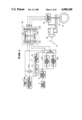
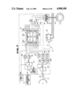
- FIG. 1 is a schematic block diagram of the first embodiment of an anti-skid brake control system according to the present invention
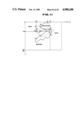
- FIG. 2 is a diagram of the preferred construction of a pressure control valve unit employed in the first embodiment of an anti-skid brake control system of FIG. 1;
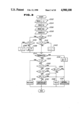
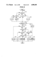
- FIG. 3 is a flowchart of a skid cycle control routine to be executed by a control unit in the first embodiment of the anti-skid brake control system of FIG. 1;
- FIG. 4 is a chart showing the schedule of selection of an operation mode of the first embodiment of the anti-skid brake control system over a skid control cycle;
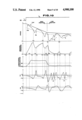
- FIG. 5 is a timing chart showing an example of anti-skid brake control operation performed by the first embodiment of the anti-skid brake control system of FIG. 1;
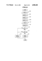
- FIG. 6 is a flowchart of a routine for selecting one of the arithmetic operation modes in a modified process of anti-skid brake control
- FIG. 7 is a schematic block diagram of the second embodiment of an anti-skid brake control system according to the present invention.
- FIG. 8 is a flowchart of a routine for deriving wheel slippage to be used in anti-skid brake control
- FIG. 9 is a flowchart of a skid cycle control routine to be executed by a control unit in the second embodiment of the anti-skid brake control system of FIG. 7;
- FIG. 10 is a timing chart showing an example of an anti-skid brake control operation performed by the second embodiment of the anti-skid brake control system of FIG. 7;
- FIG. 11 is a chart showing the schedule of selection of an operation mode of the second embodiment of the anti-skid brake control system over a skid control cycle.
- an anti-skid brake control system is associated with a hydraulic brake system.
- the brake system includes a brake pedal 17, a master cylinder 18 mechanically associated with the brake pedal 17 for building up braking pressure in response to manual input of braking force through the brake pedal, and wheel cylinders 10 of the vehicular brakes for applying braking pressure for respective front-left, front-right, rear-left and rear-right wheels 15.
- the anti-skid brake control system includes wheel speed sensors 3 respectively monitoring rotation speed of front-left, front-right, rear-left and rear-right wheels 15 to produce wheel speed indicative signals v w .
- the wheel speed sensor 3 generally comprises a rotor with a plurality of notches arranged on the outer circumference with regular intervals and a proximity switch for detecting respective notches.
- the wheel speed sensor 3 produces an alternating current signal as the wheel speed indicative signal v w having a frequency representative of the rotation speed of the wheel.
- a longitudinal acceleration sensor 22 is also provided for monitoring longitudinal acceleration exerted on a vehicular body and produce a longitudinal acceleration indicative signal Gx.
- the wheel speed sensors 3 and the longitudinal acceleration sensor 22 are connected to a control circuit including a control unit 12.
- a brake switch 1 is also connected to the control circuit. The brake switch 1 detects depression of the brake pedal 17 to produce a HIGH level braking state indicative signal BS and maintains the braking state indicative signal LOW level.
- the control circuit includes wheel speed indicative data deriving circuits 4 connected to respective wheel speed sensors 3. Each wheel speed indicative data deriving circuit 4 performs frequency-to-voltage (F/V) conversion for the wheel speed indicative signal v w to form wheel speed indicative analog data having a voltage level representative of the wheel speed as indicated by the frequency of the wheel speed indicative signal v w of the wheel speed sensor.
- the wheel speed deriving circuit 4 is connected to the control unit 12 to input the wheel speed indicative analog data V w thereto. Also, the wheel speed deriving circuit 4 is connected to first and second wheel acceleration deriving circuits 6A and 6B to feed the wheel speed indicative analog data Vw.
- Respective ones of the first and second wheel acceleration deriving circuits 6A and 6B are designed for sampling wheel speed indicative analog data Vw at given intervals which define sample periods.
- the first and second wheel acceleration deriving circuits 6A and 6B set the sampling periods in 5 msec for sampling the wheel speed indicative analog data Vw from the wheel speed derivation circuit 4 for deriving the wheel acceleration indicative analog data on the basis of the sampled wheel speed indicative analog data Vw.
- the first wheel acceleration deriving circuit 6A derives average wheel acceleration data within a predetermined first wheel acceleration deriving period including a given number of sample periods, e.g. 6 sample periods.
- the average wheel acceleration indicative data derived by the first wheel acceleration deriving circuit 6A will be hereafter represented by " ⁇ a ".
- the second wheel acceleration deriving circuit 6B derives second average wheel acceleration indicative data within a second wheel acceleration deriving period including a given number of sample periods, e.g. 12 sample periods.
- the average wheel acceleration indicative data derived by the second wheel acceleration deriving circuit 6B will be hereafter represented by " ⁇ b ".
- the first and second wheel acceleration deriving circuits 6A and 6B are connected to a selectively establishing connection between the wheel acceleration deriving circuits 6A and 6B and the control unit 12 for feeding a selected one of the first and second average wheel acceleration indicative data ⁇ a and ⁇ b to the latter.
- the selected on the first and second average wheel acceleration indicative data ⁇ a and ⁇ b will be hereafter referred to as "selected average wheel acceleration indicative data ⁇ ".
- the selector circuit 8 is also set for first and second wheel deceleration thresholds - ⁇ a 2 and - ⁇ b 2 which are selected, respectively, or a high friction road and a low friction road.
- the selector circuit 8 selects one of the first and second wheel deceleration thresholds - ⁇ a 2 and - ⁇ b 2 to be fed to the control unit 12.
- the selected one of the first and second wheel deceleration thresholds - ⁇ a 2 and - ⁇ b 2 will be hereafter referred to as "selected wheel deceleration threshold - ⁇ 2 ".
- the longitudinal acceleration sensor 2 is connected to a friction detector 7 and an integration circuit 10.
- the friction detector 7 comprises an averaging circuit 7a and a friction detecting circuit 7b.
- the averaging circuit 7a samples the longitudinal acceleration indicative signal over a predetermined sampling period and derives the average value of the sampled longitudinal acceleration indicative values Gx to derive average longitudinal acceleration data Gx.
- the friction detecting circuit 7b compares the absolute value of the average longitudinal acceleration data Gx with a predetermined longitudinal acceleration threshold Gs for discriminating between high friction road surface conditions and low friction road surface conditions.
- M is road/tire friction coefficient
- N vertical reaction force
- the longitudinal acceleration exerted on the vehicle body can be described by :
- the longitudinal acceleration Gx is proportional to the friction coefficient M. Therefore, by checking the longitudinal acceleration, the friction level on the road surface can be assumed.
- the friction detecting circuit 7b then produces a friction level indicative signal ⁇ which is variable between a HIGH level indicative of a high friction road surface condition and a LOW level indicative of a LOW friction road surface condition.
- the friction level indicative signal ⁇ is fed to the selector circuit 8.
- the selector circuit 8 is responsive to the HIGH friction indicative signal ⁇ to select the first average wheel acceleration indicative data ⁇ a as the average wheel acceleration indicative data ⁇ , and the first wheel deceleration threshold - ⁇ a 2 l as the selected wheel deceleration threshold - ⁇ 2 .
- the integration circuit 10 is also connected to the wheel speed deriving circuit 4 to receive therefrom the wheel speed indicative analog data Vw.
- the integration circuit 10 is responsive to the HIGH level braking state indicative signal BS from the brake switch 1 to latch the instantaneous value of the wheel speed indicative data Vw and starts integration of the longitudinal acceleration indicative data Gx.
- the integration circuit 10 sums the integrated value of the longitudinal acceleration indicative signal values Gx and the latched wheel speed indicative signal value V w to derive a sum value which serves as vehicle body speed representative data V ref (Vs+ ⁇
- the integration circuit 10 inputs the vehicle speed representative data V ref to the control unit 12.
- the control unit 12 comprises a microprocessor including an input interface 12a, an arithmetic circuit 12c, a memory 12d and an output interface 12b.
- the control unit 12 has an analog-to-digital (A/D) converter in the input interface 12a for converting analog form inputs into digital data so that the microprocessor may process the input data for deriving anti-skid control signal.
- the output interface 12b may include a digital-to-analog (D/A) converter for converting the digital from anti-skid brake control signal into an analog form signal for operating the pressure control valve unit 16.
- the anti-skid brake control signal comprises an induction control signal EV.
- the sample period of the first wheel acceleration deriving circuit 6A is set in 6 msec and the sample period of the second wheel acceleration deriving circuit 6B is set in an induction control signal EV (hereafter referred to as “EV signal”), a drain control signal AV (hereafter referred to as “AV signal”) and a drain pump control signal MR (hereafter referred to as "MR signal).
- EV signal induction control signal
- AV drain control signal
- MR drain pump control signal
- the pressure control valve unit 16 comprises an induction control valve 22 which will be hereafter referred to as "EV valve”, a drain control valve 25, which will be hereafter referred to as “AV valve”, a drain pump 24 and a pressure accumulator 26.
- the pressure control valve 16 has an inlet port 21 connected to the master cylinder 8 to receive the working fluid pressure built up in the latter and an outlet port 27 connected the wheel cylinder 10.
- the EV valve 22 is interposed between the inlet port 43 and the outlet port 27 for controlling introduction of the pressurized working fluid to the wheel cylinder 10.
- the AV valve 25 is connected to the outlet of the EV valve 22, the outlet port 27 at the inlet side and to the pressure accumulator 26 and the drain pump 24.
- the discharge outlet drain pump 24 is connected to the inlet port 21 via a one-way check valve 23 for returning part of working fluid in the pressure control valve unit 1 to the fluid reservoir (not shown) and designed for supplying pressurized working fluid.
- the pressure control valve unit 16 essentially operates in three mutually different operational modes. Namely, the pressure control valve unit 16 operates in an APPLICATION mode for increasing braking pressure in the wheel cylinder 10, a RELEASE mode for decreasing braking pressure in the wheel cylinder, and a HOLD mode to maintain the braking pressure constant. In the APPLICATION mode position, the EV valve 22 is maintained in open position to establish fluid communication between the master cylinder 8 and the wheel cylinder 10 and the AV valve 25 is maintained closed position for blocking fluid communication between the wheel cylinder 10 and the pressure accumulator 26. At the same time, the drain pump 24 may be held inoperative state.
- the EV valve 22 In the RELEASE mode position of the pressure control valve unit 16, the EV valve 22 is held closed to block fluid communication between the inlet port to the outlet port thereby blocking pressure supply from the master cylinder 8 to the wheel cylinder 10.
- the AV valve 25 is maintained at open position to establish fluid communication between the outlet port 27, and the pressure accumulator 26 and the drain pump 24 so that the pressurized fluid in the wheel cylinder 10 can be drained to the pressure accumulator 26 or to the fluid reservoir via the drain pump 24 and the one-way check valve 23.
- the drain pump 24 In order to drain part of the working fluid from the wheel cylinder to the fluid reservoir, the drain pump 24 is driven in this RELEASE mode.
- both the EV valve 22 and the AV valve 25 are held closed for completely disconnecting the wheel cylinder 10 from the inlet port 21 and the pressure accumulator 26.
- the EV valve 22 is held in the open position in response to the LOW level EV signal and shifted to close position in response to the HIGH level EV signal.
- the AV valve 25 is maintained at closed position as long as the AV signal is held LOW level and is opened by the HIGH level AV signal.
- the drain pump 24 is driven by the HIGH level MR signal.
- skid control cycle is scheduled as follows:
- the control unit 12 is responsive to the wheel deceleration increased across the deceleration threshold to initiate skid control cycle, upon which the skid control cycle enters into HOLD mode cycle period to place the pressure control valve unit 16 at the HOLD mode position to maintain the increased level of braking pressure constant;
- the embodiment of the anti-skid brake control system shown is triggered in response to turning ON the ignition switch to initiate power supply. Then, wheel speed sensors 3 start monitoring rotation speed of respectively corresponding wheels 15. The wheel speed sensors 3 thus continuously produce the wheel speed indicative signals v w .
- the alternating current form of wheel speed indicative signals v w is cyclically or periodically converted into digital wheel speed indicative data Vw by the A/D converter in the input interface to be processed in the control unit 12.
- the selected average wheel acceleration indicative data ⁇ and the selected wheel deceleration threshold - ⁇ 2 are read out at a step 1002.
- the wheel speed indicative data Vw is read out.
- the vehicle body speed representative data V ref is read out.
- the wheel slippage Si is derived according to the following equation:
- the wheel slippage Si is compared with a predetermined wheel slippage threshold S 0 at a step 1010.
- the wheel slippage threshold S 0 may be set at about the optimum wheel slippage range where an optimum vehicle braking efficiency can be obtained. In the embodiment, shown, the wheel slippage threshold S 0 is set at 15%.
- the CONTROLLED APPLICATION mode is introduced in order to lower the increasing speed of the braking pressure in the wheel cylinder so that the braking pressure is held at a level close to a pressure where the optimum wheel slippage is obtained and hereafter referred to as "lock pressure", for an expanded period.
- the RELEASE mode timer value L is again checked at a step 1020.
- the wheel acceleration ⁇ is compared with a predetermined acceleration threshold + ⁇ 1 at a step 1022. If the acceleration as checked at the step 1022 is greater than or equal to the wheel acceleration threshold + ⁇ 1 , it means that the wheel is not yet decelerated after initiation of increasing of the braking pressure or the wheel is accelerated during the RELEASE mode cycle period. Therefore, in order to discriminate the instantaneous status of the braking condition, a check is performed whether the skid control state indicative flag AS is set at a step 1024. When the skid control state indicative flag AS is not as checked at a step 1024, then the process goes to step 1018 for setting the operation mode to the NORMAL APPLICATION mode.
- the skid control state indicative flag AS is set as checked at the step 1024, then a judgement is made that it is the time to switch the skid control cycle from the RELEASE mode cycle period to the HOLD mode cycle period because the wheel acceleration ⁇ is held greater than the wheel acceleration threshold + ⁇ 1 and the operational mode is held in the RELEASE mode. Then, the HOLD mode cycle period is commanded at a step 1026. After commanding the HOLD mode cycle period, the process goes END.
- the skid control state indicative flag AS is checked at a step 1030. If the skid control mode indicative flag AS is not set as checked at the step 1030, process goes to the step 1018. On the other hand, when the skid control state indicative flag AS is not set as checked at the step 1030, the CONTROLLED APPLICATION mode cycle period is commanded at a step 1032.
- the RELEASE mode timer value L is set at a predetermined initial timer value L 0 which represents a period to maintain the RELEASE mode skid control cycle period after the wheel slippage Si is decreased across the wheel slippage threshold S 0 .
- the skid control state indicative flag AS is set.
- the RELEASE mode timer value L as checked at the step 1012 is greater than zero (0), then, the RELEASE mode timer value L is decremented by one (1) at a step 1040 and thereafter the process moves to the step 1014.
- the answer at the step 1020 becomes positive since the RELEASE mode timer value is greater than zero. Then, the process goes to a step 1042 to command the RELEASE mode skid control cycle period.
- the braking pressure is gradually increased according to increasing of the fluid pressure in the master cylinder 18.
- wheel acceleration ⁇ negative value: - ⁇
- wheel slippage Si is smaller than the wheel slippage threshold S 0 . Therefore, the answer in the step 1010 is held negative.
- the RELEASE mode timer value L is maintained at zero (0). Therefore, the answer at the step 1012 also becomes negative. Since the brake is applied, the answer in the step 1014 is negative to indicate that the condition for satisfying termination of the anti-skid control is not established.
- the NORMAL APPLICATION mode is repeatedly commanded at the step 1018 for increasing the braking pressure in linear fashion as illustrated in the period t 1 to t 2 . Therefore, at the initial stage of braking operation, the NORMAL APPLICATION mode skid cycle is performed for a period between t 1 to t 2 , as indicated in FIG. 5. At a time t 2 , the wheel acceleration ⁇ (- ⁇ ) decreases across the wheel deceleration threshold - ⁇ 2 , therefore, the answer in the step 1028 turns into positive.
- wheel speed After starting decreasing of the braking pressure in the RELEASE mode, wheel speed still continues to be decelerated at a gradually decreasing rate. Immediately after starting reduction of the braking pressure, the braking pressure still is held high enough to cause deceleration of the wheel and thus the wheel acceleration ⁇ still continues to be decreased toward the point d. At the point d of FIG. 4, the rate of change of the wheel acceleration ⁇ in the decelerating direction becomes zero. Then, the wheel acceleration ⁇ is gradually increased and reaches zero (0) from point d of FIG. 4 to the point e.
- wheel speed Vw n continues to increase resulting in the wheel speed indicative data becoming greater than or equal to the vehicle body speed representative V ref at a time t 5 .
- the wheel acceleration ⁇ is decreased across the wheel acceleration threshold + ⁇ 1 . Then, the CONTROLLED APPLICATION mode skid control cycle period is commanded at the step 1032 since the skid control state indicative flag AS is held in set position.
- the braking pressure in the wheel cylinder is gradually increased to decrease the wheel acceleration ⁇ across the wheel deceleration threshold - ⁇ 2 at a time t 7 .
- the HOLD mode skid control cycle period starts to maintain the braking pressure control unit a time t 8 at which the wheel slippage Si increases across the wheel slippage threshold S 0 .
- Subsequent skid cycle operations will be performed over one or more skid cycles until the skid control terminating condition set forth above is satisfied.
- the road surface friction is cyclically or continuously monitored for selecting the first and second wheel acceleration indicative data ⁇ a and ⁇ b and the first and second wheel deceleration threshold - ⁇ a 2 and - ⁇ b 2 . Therefore, even when the road surface friction level is changed during braking operation, the shown embodiment of the anti-skid control system can respond to changing of the friction on the surface condition to adapt the response characteristics to the road surface condition.
- the foregoing first embodiment employs the selector circuit 8 and the friction detector 7 as hardware for selecting the wheel acceleration indicative data and the wheel deceleration threshold, it is not essential to implement the present invention. Selection of the wheel acceleration and the wheel deceleration can be done through software process to be performed by the control unit 12. FIG. 6 shows one example of the routine to be executed by the control unit 12 for selecting the wheel acceleration indicative data and wheel deceleration threshold.
- the process shown in FIG. 6 is executed with a given interval, e.g. 5 msec.
- the instantaneous wheel speed indicative data Vw is read out at a step 1102.
- a difference of the instantaneous wheel speed indicative data Vw as read out at the step 1102 and the wheel speed indicative data read in the immediately preceding execution cycle is derived at a step 1104.
- an instantaneous wheel acceleration indicative data ⁇ n is derived at a step 1104.
- a running average ⁇ a of the wheel acceleration indicative data over a first given number of wheel acceleration indicative data ⁇ n over a first predetermined number of succeeding execution cycles is derived over six execution cycles including the current execution cycle.
- a running average ⁇ b of the wheel acceleration indicative data over a first given number of wheel acceleration indicative data ⁇ n over a first predetermined number of succeeding execution cycles is derived over twelve execution cycles including the current execution cycle.
- the longitudinal acceleration indicative data Gx is read out.
- a running average Gx is derived on the basis of the longitudinal acceleration indicative data Gx read in the step 1110, at a step 1112. Then, a check is performed whether the braking state indicative signal BS input from the brake switch 1 is HIGH or not, at a step 1114. If the braking state indicative signal BS is a HIGH level as checked as 1114, the absolute value of running average
- substantially same selection of the wheel acceleration indicative data and the wheel deceleration threshold can be done through the process illustrated in FIG. 6.
- FIG. 7 shows the second embodiment of the anti-skid brake control system according to the present invention.
- the common components to that of the foregoing embodiment set forth above may be represented by the same reference numerals and will be neglected the detailed discussion so as to simplify the disclosure.
- the longitudinal acceleration sensor 2 is connected to the control unit 12 via an A/D converter 30 for inputting the digital form longitudinal acceleration indicative data Gx.
- the integration circuit 10 inputs the vehicle body speed representative data V ref in a digital form as converted into the digital form, to the control circuit 12.
- FIG. 8 shows a routine for deriving the wheel slippage Si.
- the braking state indicative signal level BS is read out at a step 1202.
- the read braking state indicative signal level BS is checked whether it is a HIGH level or not, at a step 1204.
- the wheel acceleration indicative data ⁇ and the wheel slippage Si are cleared at a step 1206.
- the longitudinal acceleration indicative data Gx is read out at a step 1208.
- the longitudinal acceleration indicative data Gx is compared with a longitudinal acceleration threshold G 0 , at a step 1210. If the longitudinal acceleration indicative data Gx is greater than or equal to the longitudinal acceleration threshold G 0 , the first wheel acceleration indicative data ⁇ a derived by the first wheel acceleration deriving circuit 6A' is selected to read out, at a step 1212. Then, the first wheel acceleration indicative data ⁇ a is set as the wheel acceleration indicative data ⁇ at a step 1214.
- the second wheel acceleration indicative data ⁇ b derived by the second wheel acceleration deriving circuit 6B' is selected to be read out, at a step 1216. Then, at a step 1218, the second wheel acceleration indicative data ⁇ b is set as the wheel acceleration data indicative ⁇ .
- the vehicle body speed representative data V ref is read out, and subsequently at a step 1222, the maximum wheel speed indicative data Vw max are read out. Thereafter, the wheel slippage Si is derived on the basis of the vehicle speed representative data V ref and the maximum wheel speed indicative data Vw max , at a step 1224. Thereafter, the process goes to END.
- anti-skid brake control is performed through the process as shown in FIG. 9.
- the process of controlling skid control cycle is substantially the same as that of the foregoing first embodiment. Therefore, respective process steps of the routine of FIG. 9 will be represented by the same reference numerals in FIG. 3. Namely, in the shown process, the steps of the routine correspond to the steps between 1010 to 1042.
- skid control will be discussed in terms of an example of actual braking operation as illustrated in FIGS. 10 and 11.
- the braking pressure is gradually increased according to increasing of the fluid pressure in the master cylinder 18 in the NORMAL APPLICATION mode skid control cycle.
- the second wheel acceleration indicative data ⁇ b is selected as the wheel acceleration indicative data ⁇
- the second wheel deceleration threshold - ⁇ b 2 is selected as the wheel deceleration - ⁇ 2 .
- the longitudinal acceleration indicative data Gx increases across the longitudinal acceleration threshold G 0 at a time t 11 .
- the first wheel acceleration indicative data ⁇ a is selected as the wheel acceleration indicative data ⁇ and the first wheel deceleration threshold - ⁇ a 2 is selected at the time t 11 .
- wheel acceleration ⁇ negative value: - ⁇
- the wheel slippage Si is held smaller than the wheel slippage threshold S 0 . Therefore, the answer in the step 1010 is held negative.
- the RELEASE mode timer value L is maintained at zero (0). Therefore, the answer at the step 1012 also becomes negative. Since the brake is applied, the answer in the step 1014 is negative to indicate that the condition for satisfying termination of the anti-skid control is not established.
- the NORMAL APPLICATION mode is repeatedly commanded at the step 1018 for increasing the braking pressure in linear fashion as illustrated in the period t 10 to t 12 . Therefore, at the initial stage of braking operation, the NORMAL APPLICATION mode skid cycle is performed for a period between t 10 to t 12 , as indicated in FIG. 10, At a time t 12 , the wheel acceleration ⁇ (- ⁇ ) decrease across the wheel deceleration threshold - ⁇ 2 , therefore, the answer in the step 1028 turns into positive.
- the HOLD mode skid control cycle period is commanded at the step 1026. Therefore, the anti-skid control system becomes active for performing anti-skid brake control operation.
- the HOLD mode skid control cycle period is maintained with a period between t 12 and t 13 until the wheel slippage Si is increased across the wheel slippage threshold S 0 at the time t 13 .
- the answer in the step 1010 becomes positive.
- the wheel acceleration ⁇ is maintained smaller than the wheel acceleration threshold + ⁇ 2 . Therefore, the answer in the step 1034 becomes negative. This causes setting of the RELEASE mode timer value L to the initial value L 0 and setting of the skid control state indicative flag AS, at the step 1038.
- the answer in the step 1020 becomes positive to command RELEASE mode skid control cycle period at the step 1042.
- step 1010 After starting decreasing of the braking pressure in the RELEASE mode, wheel speed still continue to be decelerated at a gradually decreasing rate. The rate of changing of the wheel acceleration ⁇ in the decelerating direction becomes zero. Then, the wheel acceleration ⁇ is gradually increased and reaches zero (0). Though the RELEASE mode, the decreasing rate of the wheel speed becomes zero and subsequently increase toward the vehicle body speed to decrease wheel slippage Si across the wheel slippage threshold S 0 . This results in negative answer in the step 1010. As long as the RELEASE mode timer value L is held greater than zero (0), the answer in the step 1012 is held positive and is decreased by one (1) every occurrence of execution of the routine of FIG. 3.
- the RELEASE mode skid control cycle period is repeatedly commanded for maintaining the pressure control valve 16 at the RELEASE mode position, as illustrated by the period between t 13 and t 14 .
- the wheel acceleration indicative data ⁇ once increased decreases across the wheel acceleration threshold ⁇ 1 , at a time t 15 . Then, the CONTROLLED APPLICATION mode skid control cycle period is commanded at the step 1032 since the skid control state indicative flag AS is held in set position.
- the braking pressure in the wheel cylinder is gradually increased to decrease the wheel acceleration ⁇ across the wheel deceleration threshold - ⁇ 2 at a time t 16 .
- HOLD mode skid control cycle period starts to maintain the braking pressure control unit ⁇ time t 17 at which the wheel slippage Si increases across the wheel slippage threshold S 0 .
- Subsequent skid cycle operations will be performed over one or more skid cycles until the skid control terminating condition set forth above is satisfied through the times t 18 to t 28 .
- the longitudinal acceleration indicative data Gx decreases across the longitudinal acceleration threshold G 0 , then, the second wheel acceleration indicative data ⁇ b is selected as the wheel acceleration indicative data ⁇ and the second wheel acceleration threshold - ⁇ b 2 is selected as the wheel deceleration threshold - 2 .
- the first wheel acceleration indicative data ⁇ 1 which is provided higher sensitivity may fluctuate according to fluctuation of the wheel speed Vw.
- no fluctuation can be observed in the second wheel acceleration indicative data ⁇ b because of lower sensitivity. Since after the time t 20 , the second wheel acceleration indicative data ⁇ b and the second wheel deceleration threshold - ⁇ 2 are selected, no influence of the fluctuation of the wheel speed will be caused for controlling the skid control cycle in the anti-skid control.
Landscapes
- Engineering & Computer Science (AREA)
- Transportation (AREA)
- Mechanical Engineering (AREA)
- Regulating Braking Force (AREA)
Applications Claiming Priority (4)
| Application Number | Priority Date | Filing Date | Title |
|---|---|---|---|
| JP63-46696 | 1988-02-29 | ||
| JP63046696A JP2650305B2 (ja) | 1988-02-29 | 1988-02-29 | アンチスキッド制御装置 |
| JP63046695A JP2661106B2 (ja) | 1988-02-29 | 1988-02-29 | アンチスキッド制御装置 |
| JP63-46695 | 1988-02-29 |
Publications (1)
| Publication Number | Publication Date |
|---|---|
| US4900100A true US4900100A (en) | 1990-02-13 |
Family
ID=26386804
Family Applications (1)
| Application Number | Title | Priority Date | Filing Date |
|---|---|---|---|
| US07/316,742 Expired - Lifetime US4900100A (en) | 1988-02-29 | 1989-02-28 | Anti-skid brake control system with capability of eliminating influence of noise in derivation of wheel acceleration data |
Country Status (3)
| Country | Link |
|---|---|
| US (1) | US4900100A (fr) |
| EP (1) | EP0331133B1 (fr) |
| DE (1) | DE68926827T2 (fr) |
Cited By (15)
| Publication number | Priority date | Publication date | Assignee | Title |
|---|---|---|---|---|
| US5071200A (en) * | 1989-10-12 | 1991-12-10 | Eaton Corporation | Abs pressure reapply logic |
| US5125723A (en) * | 1989-11-10 | 1992-06-30 | Tokico Ltd. | Antilock brake control apparatus |
| US5132906A (en) * | 1990-06-11 | 1992-07-21 | Ford Motor Company | Road surface friction and hill slope estimator |
| US5200896A (en) * | 1989-09-07 | 1993-04-06 | Honda Giken Kogyo Kabushiki Kaisha | Method for estimating longitudinal acceleration or deceleration of a vehicle body |
| US5243526A (en) * | 1990-05-18 | 1993-09-07 | Mitsubishi Jidosha Kogyo Kabushiki Kaisha | Output control apparatus for vehicle |
| US5280432A (en) * | 1989-08-05 | 1994-01-18 | Aisin Seiki Kabushiki Kaisha | Anti-skid brake control system based on acceleration detection |
| US5307213A (en) * | 1990-11-30 | 1994-04-26 | Hitachi, Ltd. | Data reproducing apparatus for eliminating undershoots in the vicinity of the outer edges of a magnetic pole |
| US5608631A (en) * | 1993-03-16 | 1997-03-04 | Mitsubishi Denki Kabushiki Kaisha | Apparatus and method for detecting acceleration of motor vehicle with high accuracy and anti-skid control apparatus using the same |
| US5748503A (en) * | 1995-07-04 | 1998-05-05 | Toyota Jidosha Kabushiki Kaisha | Apparatus for estimating vehicle speed based on detected wheel speed, without influence of noise included in the detected wheel speed |
| US5938713A (en) * | 1988-10-13 | 1999-08-17 | Japan Electronics Industry, Limited | Vehicle antilock braking device |
| US6301540B1 (en) * | 1998-05-26 | 2001-10-09 | Aisin Seiki | System for detecting difference in road level |
| US6354675B1 (en) * | 1997-05-22 | 2002-03-12 | Japan Electronics Industry Ltd. | ABS apparatus |
| US6753047B1 (en) | 1999-06-10 | 2004-06-22 | Ppg Industries Ohio, Inc. | Electrodes for liquid crystal cells |
| US20060250023A1 (en) * | 1993-04-21 | 2006-11-09 | Japan Electronics Industry, Limited | Method of controlling anti-lock brake system for vehicles and method of finding control point in ABS |
| US20160328889A1 (en) * | 2015-05-05 | 2016-11-10 | Bendix Commercial Vehicle Systems Llc | Method and Apparatus for Determining a Wheel End Condition |
Families Citing this family (4)
| Publication number | Priority date | Publication date | Assignee | Title |
|---|---|---|---|---|
| JPH03246157A (ja) * | 1990-02-23 | 1991-11-01 | Toyota Motor Corp | アンチスキッド制御装置 |
| US5171069A (en) * | 1990-04-23 | 1992-12-15 | Rockwell International Corporation | Antilock brake system and method incorporating a pressure feedback |
| JP3662596B2 (ja) * | 1991-01-14 | 2005-06-22 | 住友電気工業株式会社 | 推定車体速度等の算出装置 |
| CN117901814B (zh) * | 2024-03-15 | 2024-05-24 | 山西承信新能源科技装备有限公司 | 一种基于噪声控制的无轨胶轮车 |
Citations (49)
| Publication number | Priority date | Publication date | Assignee | Title |
|---|---|---|---|---|
| US3235036A (en) * | 1962-10-31 | 1966-02-15 | Research Corp | Brake control system |
| US3401983A (en) * | 1967-01-24 | 1968-09-17 | Henriette L Williams | Vehicle brake control |
| US3508795A (en) * | 1967-03-28 | 1970-04-28 | Kelsey Hayes Co | Anti-skid braking system |
| US3547500A (en) * | 1969-03-06 | 1970-12-15 | Kelsey Hayes Co | Skid control system |
| US3656816A (en) * | 1969-07-09 | 1972-04-18 | Itt | Braking system with deceleration derivative control |
| US3744852A (en) * | 1971-08-23 | 1973-07-10 | Kelsey Hayes Co | Skid control system |
| US3790227A (en) * | 1972-06-30 | 1974-02-05 | North American Rockwell | Brake control system |
| US3863993A (en) * | 1971-09-18 | 1975-02-04 | Bosch Gmbh Robert | Wheel braking control system |
| US3871715A (en) * | 1971-05-04 | 1975-03-18 | Toyoda Chuo Kenkyusho Kk | Automatic brake controlling method and device |
| US3874741A (en) * | 1972-09-07 | 1975-04-01 | Bosch Gmbh Robert | Wheel brake antilock system with noise signal rejection circuit |
| US3904251A (en) * | 1972-05-15 | 1975-09-09 | Toyoda Chuo Kenkyusho Kk | Automatic skid reduction control method and device for a braking system |
| US3922022A (en) * | 1973-02-09 | 1975-11-25 | Toyota Motor Co Ltd | Skid control braking system |
| US3988042A (en) * | 1973-07-21 | 1976-10-26 | Akebono Brake Industry Co., Ltd. | Vehicle antiskid control system |
| US4037882A (en) * | 1975-11-20 | 1977-07-26 | General Motors Corporation | Anti-lock brake control circuit |
| US4039227A (en) * | 1976-04-16 | 1977-08-02 | Kelsey-Hayes Company | Skid control system having a switched low speed noise filter |
| US4043608A (en) * | 1971-08-13 | 1977-08-23 | Daimler-Benz Aktiengesellschaft | Brake force control device for back-control |
| US4076332A (en) * | 1977-01-24 | 1978-02-28 | General Motors Corporation | Wheel lock control circuit |
| US4275933A (en) * | 1976-09-06 | 1981-06-30 | Akebono Brake Industry Co. Ltd. | Antiskid device |
| US4408290A (en) * | 1980-01-14 | 1983-10-04 | Nissan Motor Company, Limited | Method and device for determining acceleration and/or deceleration of a moving object |
| US4570560A (en) * | 1984-04-06 | 1986-02-18 | Pfaff Industriemaschinen Gmbh | Stop motion device for sewing, embroidering or tufting machines |
| US4597052A (en) * | 1983-05-17 | 1986-06-24 | Nissan Motor Company, Limited | Digital control system with error monitor operative upon starting system operation |
| US4637663A (en) * | 1983-08-11 | 1987-01-20 | Nissan Motor Company, Limited | Anti-skid brake control system performing skid control with both open and close feedback techniques |
| US4651281A (en) * | 1983-08-09 | 1987-03-17 | Nippondenso Co., Ltd. | Antiskid control with wheel-speed difference compensation |
| US4656588A (en) * | 1984-04-17 | 1987-04-07 | Nissan Motor Company, Limited | Anti-skid brake control system with a plurality of independently operative digital controllers |
| US4660146A (en) * | 1983-04-23 | 1987-04-21 | Nissan Motor Company, Limited | Anti-lock brake control system including a procedure of sampling of input time data of wheel speed sensor signals and method therefor |
| US4663716A (en) * | 1983-04-23 | 1987-05-05 | Nissan Motor Company, Limited | Anti-skid control system for automotive brake system with sample control for sampling input timing of sensor signal pulses with required process identification and method for sampling |
| US4663715A (en) * | 1983-04-23 | 1987-05-05 | Nissan Motor Company, Limited | Automotive anti-skid control system with control of sampling of input time data of wheel speed sensor signals and method therefor |
| US4662686A (en) * | 1983-05-16 | 1987-05-05 | Nissan Motor Company, Limited | Anti-skid brake control system performing skid control with both open and close feedback techniques |
| US4664453A (en) * | 1985-10-21 | 1987-05-12 | General Motors Corporation | Anti-lock brake control system |
| US4665491A (en) * | 1983-04-23 | 1987-05-12 | Nissan Motor Company, Limited | Anti-skid brake control system with sample control of sensor signal input time data, and method therefor |
| US4667176A (en) * | 1983-05-17 | 1987-05-19 | Nissan Motor Company, Limited | Failure-monitor system for an automotive digital control system |
| US4669046A (en) * | 1983-05-16 | 1987-05-26 | Nissan Motor Company, Limited | Method and system for deriving wheel rotation speed data for automotive anti-skid control |
| US4669045A (en) * | 1983-05-16 | 1987-05-26 | Nissan Motor Company, Limited | Method and system for deriving wheel acceleration and deceleration in automotive anti-skid brake control systems |
| US4674050A (en) * | 1983-04-23 | 1987-06-16 | Nissan Motor Company, Limited | Anti-skid brake control system for automotive vehicle |
| US4674049A (en) * | 1983-04-23 | 1987-06-16 | Nissan Motor Company, Limited | Automotive anti-skid brake control system with sampling input time data of wheel speed sensor signals |
| US4680713A (en) * | 1983-05-16 | 1987-07-14 | Nissan Motor Company, Limited | Anti-skid brake control system with operation control for a pressure reduction fluid pump in hydraulic brake circuit |
| US4680714A (en) * | 1983-04-23 | 1987-07-14 | Nissan Motor Company, Limited | Anti-skid brake control system with reduced duration of wheel acceleration and deceleration calculation |
| US4682295A (en) * | 1983-05-16 | 1987-07-21 | Nissan Motor Company, Limited | Anti-skid brake control system with operational mode control and method therefor |
| US4683537A (en) * | 1983-11-09 | 1987-07-28 | Nissan Motor Company, Limited | Anti-skid brake control system for automotive brake system with quick take-up feature |
| US4693522A (en) * | 1985-01-11 | 1987-09-15 | Alfred Teves Gmbh | Process and circuit arrangement for adapting slip control to the momentary friction value |
| US4704684A (en) * | 1983-04-23 | 1987-11-03 | Nissan Motor Company, Limited | Method and system for sampling input time data for wheel speed sensor in an automotive anti-skid brake control system |
| US4715662A (en) * | 1983-12-16 | 1987-12-29 | Robert Bosch Gmbh | Method for determining an optimal slip value |
| US4718013A (en) * | 1983-05-16 | 1988-01-05 | Nissan Motor Company, Limited | Method and system for deriving wheel rotation speed data for automotive anti-skid control |
| US4763260A (en) * | 1985-11-20 | 1988-08-09 | Tokico Ltd. | Antiskid control device |
| US4776644A (en) * | 1986-09-05 | 1988-10-11 | Nippon A B S, Ltd. | Anti-skid control apparatus for a vehicle braking system |
| US4780818A (en) * | 1983-04-23 | 1988-10-25 | Nissan Motor Company, Limited | Anti-skid brake control system with control of sampling timing of input timing values of wheel speed sensor signal pulses |
| US4783127A (en) * | 1985-10-21 | 1988-11-08 | General Motors Corporation | Anti-lock brake control system |
| US4807133A (en) * | 1986-05-09 | 1989-02-21 | Akebono Brake Industry Co., Ltd. | Anti-skid control system for motor vehicles |
| US4836619A (en) * | 1987-01-26 | 1989-06-06 | Honda Giken Kogyo Kabushiki Kaisha | Anti-lock control method for vehicle |
Family Cites Families (4)
| Publication number | Priority date | Publication date | Assignee | Title |
|---|---|---|---|---|
| KR840001899A (ko) * | 1981-10-31 | 1984-06-07 | 에드먼드 죤 페이지 | 차륜 슬립 제어장치 |
| JPS6035647A (ja) * | 1983-08-09 | 1985-02-23 | Nippon Denso Co Ltd | アンチスキツド制御装置 |
| DE3717531C2 (de) * | 1986-05-30 | 1993-12-23 | Tokico Ltd | Schaltungsanordnung zum Bestimmen der Referenzgeschwindigkeit in einer blockiergeschützten Fahrzeug-Bremsanlage |
| DE3709483A1 (de) * | 1987-03-23 | 1988-10-06 | Bosch Gmbh Robert | Antiblockierregelsystem |
-
1989
- 1989-02-28 US US07/316,742 patent/US4900100A/en not_active Expired - Lifetime
- 1989-02-28 DE DE68926827T patent/DE68926827T2/de not_active Expired - Lifetime
- 1989-02-28 EP EP89103534A patent/EP0331133B1/fr not_active Expired - Lifetime
Patent Citations (49)
| Publication number | Priority date | Publication date | Assignee | Title |
|---|---|---|---|---|
| US3235036A (en) * | 1962-10-31 | 1966-02-15 | Research Corp | Brake control system |
| US3401983A (en) * | 1967-01-24 | 1968-09-17 | Henriette L Williams | Vehicle brake control |
| US3508795A (en) * | 1967-03-28 | 1970-04-28 | Kelsey Hayes Co | Anti-skid braking system |
| US3547500A (en) * | 1969-03-06 | 1970-12-15 | Kelsey Hayes Co | Skid control system |
| US3656816A (en) * | 1969-07-09 | 1972-04-18 | Itt | Braking system with deceleration derivative control |
| US3871715A (en) * | 1971-05-04 | 1975-03-18 | Toyoda Chuo Kenkyusho Kk | Automatic brake controlling method and device |
| US4043608A (en) * | 1971-08-13 | 1977-08-23 | Daimler-Benz Aktiengesellschaft | Brake force control device for back-control |
| US3744852A (en) * | 1971-08-23 | 1973-07-10 | Kelsey Hayes Co | Skid control system |
| US3863993A (en) * | 1971-09-18 | 1975-02-04 | Bosch Gmbh Robert | Wheel braking control system |
| US3904251A (en) * | 1972-05-15 | 1975-09-09 | Toyoda Chuo Kenkyusho Kk | Automatic skid reduction control method and device for a braking system |
| US3790227A (en) * | 1972-06-30 | 1974-02-05 | North American Rockwell | Brake control system |
| US3874741A (en) * | 1972-09-07 | 1975-04-01 | Bosch Gmbh Robert | Wheel brake antilock system with noise signal rejection circuit |
| US3922022A (en) * | 1973-02-09 | 1975-11-25 | Toyota Motor Co Ltd | Skid control braking system |
| US3988042A (en) * | 1973-07-21 | 1976-10-26 | Akebono Brake Industry Co., Ltd. | Vehicle antiskid control system |
| US4037882A (en) * | 1975-11-20 | 1977-07-26 | General Motors Corporation | Anti-lock brake control circuit |
| US4039227A (en) * | 1976-04-16 | 1977-08-02 | Kelsey-Hayes Company | Skid control system having a switched low speed noise filter |
| US4275933A (en) * | 1976-09-06 | 1981-06-30 | Akebono Brake Industry Co. Ltd. | Antiskid device |
| US4076332A (en) * | 1977-01-24 | 1978-02-28 | General Motors Corporation | Wheel lock control circuit |
| US4408290A (en) * | 1980-01-14 | 1983-10-04 | Nissan Motor Company, Limited | Method and device for determining acceleration and/or deceleration of a moving object |
| US4660146A (en) * | 1983-04-23 | 1987-04-21 | Nissan Motor Company, Limited | Anti-lock brake control system including a procedure of sampling of input time data of wheel speed sensor signals and method therefor |
| US4665491A (en) * | 1983-04-23 | 1987-05-12 | Nissan Motor Company, Limited | Anti-skid brake control system with sample control of sensor signal input time data, and method therefor |
| US4780818A (en) * | 1983-04-23 | 1988-10-25 | Nissan Motor Company, Limited | Anti-skid brake control system with control of sampling timing of input timing values of wheel speed sensor signal pulses |
| US4704684A (en) * | 1983-04-23 | 1987-11-03 | Nissan Motor Company, Limited | Method and system for sampling input time data for wheel speed sensor in an automotive anti-skid brake control system |
| US4680714A (en) * | 1983-04-23 | 1987-07-14 | Nissan Motor Company, Limited | Anti-skid brake control system with reduced duration of wheel acceleration and deceleration calculation |
| US4674049A (en) * | 1983-04-23 | 1987-06-16 | Nissan Motor Company, Limited | Automotive anti-skid brake control system with sampling input time data of wheel speed sensor signals |
| US4663716A (en) * | 1983-04-23 | 1987-05-05 | Nissan Motor Company, Limited | Anti-skid control system for automotive brake system with sample control for sampling input timing of sensor signal pulses with required process identification and method for sampling |
| US4663715A (en) * | 1983-04-23 | 1987-05-05 | Nissan Motor Company, Limited | Automotive anti-skid control system with control of sampling of input time data of wheel speed sensor signals and method therefor |
| US4674050A (en) * | 1983-04-23 | 1987-06-16 | Nissan Motor Company, Limited | Anti-skid brake control system for automotive vehicle |
| US4662686A (en) * | 1983-05-16 | 1987-05-05 | Nissan Motor Company, Limited | Anti-skid brake control system performing skid control with both open and close feedback techniques |
| US4680713A (en) * | 1983-05-16 | 1987-07-14 | Nissan Motor Company, Limited | Anti-skid brake control system with operation control for a pressure reduction fluid pump in hydraulic brake circuit |
| US4682295A (en) * | 1983-05-16 | 1987-07-21 | Nissan Motor Company, Limited | Anti-skid brake control system with operational mode control and method therefor |
| US4669046A (en) * | 1983-05-16 | 1987-05-26 | Nissan Motor Company, Limited | Method and system for deriving wheel rotation speed data for automotive anti-skid control |
| US4669045A (en) * | 1983-05-16 | 1987-05-26 | Nissan Motor Company, Limited | Method and system for deriving wheel acceleration and deceleration in automotive anti-skid brake control systems |
| US4718013A (en) * | 1983-05-16 | 1988-01-05 | Nissan Motor Company, Limited | Method and system for deriving wheel rotation speed data for automotive anti-skid control |
| US4597052A (en) * | 1983-05-17 | 1986-06-24 | Nissan Motor Company, Limited | Digital control system with error monitor operative upon starting system operation |
| US4667176A (en) * | 1983-05-17 | 1987-05-19 | Nissan Motor Company, Limited | Failure-monitor system for an automotive digital control system |
| US4651281A (en) * | 1983-08-09 | 1987-03-17 | Nippondenso Co., Ltd. | Antiskid control with wheel-speed difference compensation |
| US4637663A (en) * | 1983-08-11 | 1987-01-20 | Nissan Motor Company, Limited | Anti-skid brake control system performing skid control with both open and close feedback techniques |
| US4683537A (en) * | 1983-11-09 | 1987-07-28 | Nissan Motor Company, Limited | Anti-skid brake control system for automotive brake system with quick take-up feature |
| US4715662A (en) * | 1983-12-16 | 1987-12-29 | Robert Bosch Gmbh | Method for determining an optimal slip value |
| US4570560A (en) * | 1984-04-06 | 1986-02-18 | Pfaff Industriemaschinen Gmbh | Stop motion device for sewing, embroidering or tufting machines |
| US4656588A (en) * | 1984-04-17 | 1987-04-07 | Nissan Motor Company, Limited | Anti-skid brake control system with a plurality of independently operative digital controllers |
| US4693522A (en) * | 1985-01-11 | 1987-09-15 | Alfred Teves Gmbh | Process and circuit arrangement for adapting slip control to the momentary friction value |
| US4664453A (en) * | 1985-10-21 | 1987-05-12 | General Motors Corporation | Anti-lock brake control system |
| US4783127A (en) * | 1985-10-21 | 1988-11-08 | General Motors Corporation | Anti-lock brake control system |
| US4763260A (en) * | 1985-11-20 | 1988-08-09 | Tokico Ltd. | Antiskid control device |
| US4807133A (en) * | 1986-05-09 | 1989-02-21 | Akebono Brake Industry Co., Ltd. | Anti-skid control system for motor vehicles |
| US4776644A (en) * | 1986-09-05 | 1988-10-11 | Nippon A B S, Ltd. | Anti-skid control apparatus for a vehicle braking system |
| US4836619A (en) * | 1987-01-26 | 1989-06-06 | Honda Giken Kogyo Kabushiki Kaisha | Anti-lock control method for vehicle |
Cited By (18)
| Publication number | Priority date | Publication date | Assignee | Title |
|---|---|---|---|---|
| US6266600B1 (en) * | 1988-10-13 | 2001-07-24 | Japan Electronics Industry, Ltd. | Road surface friction sensor and road surface friction coefficient detector, and vehicle antilock braking device |
| US5938713A (en) * | 1988-10-13 | 1999-08-17 | Japan Electronics Industry, Limited | Vehicle antilock braking device |
| US5280432A (en) * | 1989-08-05 | 1994-01-18 | Aisin Seiki Kabushiki Kaisha | Anti-skid brake control system based on acceleration detection |
| US5200896A (en) * | 1989-09-07 | 1993-04-06 | Honda Giken Kogyo Kabushiki Kaisha | Method for estimating longitudinal acceleration or deceleration of a vehicle body |
| US5071200A (en) * | 1989-10-12 | 1991-12-10 | Eaton Corporation | Abs pressure reapply logic |
| USRE35547E (en) * | 1989-11-10 | 1997-07-01 | Tokico Ltd. | Antilock brake control apparatus |
| US5125723A (en) * | 1989-11-10 | 1992-06-30 | Tokico Ltd. | Antilock brake control apparatus |
| US5243526A (en) * | 1990-05-18 | 1993-09-07 | Mitsubishi Jidosha Kogyo Kabushiki Kaisha | Output control apparatus for vehicle |
| US5132906A (en) * | 1990-06-11 | 1992-07-21 | Ford Motor Company | Road surface friction and hill slope estimator |
| US5307213A (en) * | 1990-11-30 | 1994-04-26 | Hitachi, Ltd. | Data reproducing apparatus for eliminating undershoots in the vicinity of the outer edges of a magnetic pole |
| US5608631A (en) * | 1993-03-16 | 1997-03-04 | Mitsubishi Denki Kabushiki Kaisha | Apparatus and method for detecting acceleration of motor vehicle with high accuracy and anti-skid control apparatus using the same |
| US20060250023A1 (en) * | 1993-04-21 | 2006-11-09 | Japan Electronics Industry, Limited | Method of controlling anti-lock brake system for vehicles and method of finding control point in ABS |
| US5748503A (en) * | 1995-07-04 | 1998-05-05 | Toyota Jidosha Kabushiki Kaisha | Apparatus for estimating vehicle speed based on detected wheel speed, without influence of noise included in the detected wheel speed |
| US6354675B1 (en) * | 1997-05-22 | 2002-03-12 | Japan Electronics Industry Ltd. | ABS apparatus |
| US6301540B1 (en) * | 1998-05-26 | 2001-10-09 | Aisin Seiki | System for detecting difference in road level |
| US6753047B1 (en) | 1999-06-10 | 2004-06-22 | Ppg Industries Ohio, Inc. | Electrodes for liquid crystal cells |
| US20160328889A1 (en) * | 2015-05-05 | 2016-11-10 | Bendix Commercial Vehicle Systems Llc | Method and Apparatus for Determining a Wheel End Condition |
| US9652903B2 (en) * | 2015-05-05 | 2017-05-16 | Bendix Commercial Vehicle Systems Llc | Method and apparatus for determining a wheel end condition |
Also Published As
| Publication number | Publication date |
|---|---|
| EP0331133B1 (fr) | 1996-07-17 |
| EP0331133A2 (fr) | 1989-09-06 |
| DE68926827T2 (de) | 1996-11-21 |
| DE68926827D1 (de) | 1996-08-22 |
| EP0331133A3 (fr) | 1992-05-06 |
Similar Documents
| Publication | Publication Date | Title |
|---|---|---|
| US4900100A (en) | Anti-skid brake control system with capability of eliminating influence of noise in derivation of wheel acceleration data | |
| US4384330A (en) | Brake control system for an automotive vehicle | |
| JP2565865B2 (ja) | アンチスキツドブレ−キシステムのスリツプ制御方法及びその装置 | |
| US5072393A (en) | Antiskid control system | |
| EP0133812B1 (fr) | Commande antidéparage à compensation de frottement de surface | |
| US4974163A (en) | Anti-skid brake control system with derivation of precise projected vehicle body speed data utilizing longitudinal acceleration exerted on the vehicle body | |
| US4660146A (en) | Anti-lock brake control system including a procedure of sampling of input time data of wheel speed sensor signals and method therefor | |
| US4680714A (en) | Anti-skid brake control system with reduced duration of wheel acceleration and deceleration calculation | |
| US4674050A (en) | Anti-skid brake control system for automotive vehicle | |
| US4669045A (en) | Method and system for deriving wheel acceleration and deceleration in automotive anti-skid brake control systems | |
| US4657314A (en) | Apparatus and method of controlling braking of an automotive vehicle, operating in a curved path | |
| US4962455A (en) | Anti-skid brake control system with feature of projection of vehicle body speed representative data with high precision | |
| US4780818A (en) | Anti-skid brake control system with control of sampling timing of input timing values of wheel speed sensor signal pulses | |
| US4933858A (en) | Anti-skid brake control system for an automotive brake system having variable deceleration threshold | |
| US4663716A (en) | Anti-skid control system for automotive brake system with sample control for sampling input timing of sensor signal pulses with required process identification and method for sampling | |
| EP0422515B1 (fr) | Logique de réapplication de la pression ABS | |
| EP0176785B1 (fr) | Système de réglage de glissage des roues | |
| US4919494A (en) | Anti-skid brake control system with avoidance of abrupt and substantial variation of wheel slippage | |
| US4970649A (en) | Anti-skid brake control system with projected vehicle speed derivation with variable gradient depending upon vehicular braking condition | |
| US5003481A (en) | Anti-skid brake control system for automotive brake system including projection of vehicular speed representative data | |
| US4852951A (en) | Anti-skid brake control system with feature for assuring derivation of vehicle speed representing value precisely reflecting actual vehicle speed | |
| US4809182A (en) | Anti-skid brake control system with simultaneous locking preventive feature | |
| US4980832A (en) | Fail-safe system for an anti-skid control system for an automotive brake system | |
| US5104204A (en) | Antiskid brake control system | |
| US4964047A (en) | Anti-skid brake control system for automotive brake system with projection of vehicular speed representative data on the basis of longitudinal acceleration exerted on vehicle body |
Legal Events
| Date | Code | Title | Description |
|---|---|---|---|
| AS | Assignment |
Owner name: NISSAN MOTOR COMPANY, LIMITED, JAPAN Free format text: ASSIGNMENT OF ASSIGNORS INTEREST.;ASSIGNORS:HIGASHIMATA, AKIRA;ISHIKAWA, YASUKI;YASUNO, YOSHIKI;AND OTHERS;REEL/FRAME:005078/0365 Effective date: 19890411 |
|
| STCF | Information on status: patent grant |
Free format text: PATENTED CASE |
|
| FEPP | Fee payment procedure |
Free format text: PAYOR NUMBER ASSIGNED (ORIGINAL EVENT CODE: ASPN); ENTITY STATUS OF PATENT OWNER: LARGE ENTITY |
|
| FPAY | Fee payment |
Year of fee payment: 4 |
|
| FPAY | Fee payment |
Year of fee payment: 8 |
|
| FPAY | Fee payment |
Year of fee payment: 12 |