US4901254A - Method and apparatus for influencing the colour appearance of a colored area in a printing process - Google Patents
Method and apparatus for influencing the colour appearance of a colored area in a printing process Download PDFInfo
- Publication number
- US4901254A US4901254A US07/073,444 US7344487A US4901254A US 4901254 A US4901254 A US 4901254A US 7344487 A US7344487 A US 7344487A US 4901254 A US4901254 A US 4901254A
- Authority
- US
- United States
- Prior art keywords
- colour
- coloured
- separation
- proportion
- colours
- Prior art date
- Legal status (The legal status is an assumption and is not a legal conclusion. Google has not performed a legal analysis and makes no representation as to the accuracy of the status listed.)
- Expired - Fee Related
Links
- 238000000034 method Methods 0.000 title claims abstract description 75
- 238000007639 printing Methods 0.000 title claims abstract description 45
- 230000008569 process Effects 0.000 title claims abstract description 33
- 238000000926 separation method Methods 0.000 claims abstract description 129
- 239000003086 colorant Substances 0.000 claims abstract description 100
- 239000013598 vector Substances 0.000 claims abstract description 56
- 238000005259 measurement Methods 0.000 claims abstract description 29
- 238000012360 testing method Methods 0.000 claims description 44
- 238000000326 densiometry Methods 0.000 claims description 16
- 229920006395 saturated elastomer Polymers 0.000 claims description 9
- 230000007935 neutral effect Effects 0.000 claims description 7
- 238000012935 Averaging Methods 0.000 claims description 3
- 239000000523 sample Substances 0.000 description 28
- 230000004075 alteration Effects 0.000 description 20
- 238000004519 manufacturing process Methods 0.000 description 18
- 230000001105 regulatory effect Effects 0.000 description 15
- 238000010586 diagram Methods 0.000 description 14
- 239000007787 solid Substances 0.000 description 13
- 238000012937 correction Methods 0.000 description 10
- 238000007645 offset printing Methods 0.000 description 8
- 230000015572 biosynthetic process Effects 0.000 description 6
- 230000015556 catabolic process Effects 0.000 description 6
- 238000010276 construction Methods 0.000 description 6
- 238000004737 colorimetric analysis Methods 0.000 description 5
- 238000003786 synthesis reaction Methods 0.000 description 5
- 238000004364 calculation method Methods 0.000 description 4
- 239000000203 mixture Substances 0.000 description 4
- 238000012545 processing Methods 0.000 description 4
- 230000007363 regulatory process Effects 0.000 description 4
- 238000007650 screen-printing Methods 0.000 description 4
- 230000002349 favourable effect Effects 0.000 description 3
- 230000003287 optical effect Effects 0.000 description 3
- 238000003359 percent control normalization Methods 0.000 description 3
- 230000009467 reduction Effects 0.000 description 3
- 238000012546 transfer Methods 0.000 description 3
- 238000004458 analytical method Methods 0.000 description 2
- 238000006243 chemical reaction Methods 0.000 description 2
- 230000001276 controlling effect Effects 0.000 description 2
- 230000001419 dependent effect Effects 0.000 description 2
- 238000007641 inkjet printing Methods 0.000 description 2
- 239000011159 matrix material Substances 0.000 description 2
- 238000005375 photometry Methods 0.000 description 2
- 238000009877 rendering Methods 0.000 description 2
- 230000009897 systematic effect Effects 0.000 description 2
- 238000001931 thermography Methods 0.000 description 2
- ZYECOAILUNWEAL-NUDFZHEQSA-N (4z)-4-[[2-methoxy-5-(phenylcarbamoyl)phenyl]hydrazinylidene]-n-(3-nitrophenyl)-3-oxonaphthalene-2-carboxamide Chemical compound COC1=CC=C(C(=O)NC=2C=CC=CC=2)C=C1N\N=C(C1=CC=CC=C1C=1)/C(=O)C=1C(=O)NC1=CC=CC([N+]([O-])=O)=C1 ZYECOAILUNWEAL-NUDFZHEQSA-N 0.000 description 1
- 240000007817 Olea europaea Species 0.000 description 1
- 235000005811 Viola adunca Nutrition 0.000 description 1
- 240000009038 Viola odorata Species 0.000 description 1
- 235000013487 Viola odorata Nutrition 0.000 description 1
- 235000002254 Viola papilionacea Nutrition 0.000 description 1
- 230000009471 action Effects 0.000 description 1
- 230000008901 benefit Effects 0.000 description 1
- 230000000295 complement effect Effects 0.000 description 1
- 239000002537 cosmetic Substances 0.000 description 1
- 238000013016 damping Methods 0.000 description 1
- 230000007547 defect Effects 0.000 description 1
- 238000001739 density measurement Methods 0.000 description 1
- 230000000694 effects Effects 0.000 description 1
- 230000008030 elimination Effects 0.000 description 1
- 238000003379 elimination reaction Methods 0.000 description 1
- 238000005516 engineering process Methods 0.000 description 1
- 238000011156 evaluation Methods 0.000 description 1
- 230000006870 function Effects 0.000 description 1
- 238000007646 gravure printing Methods 0.000 description 1
- 238000007644 letterpress printing Methods 0.000 description 1
- YTCQFLFGFXZUSN-BAQGIRSFSA-N microline Chemical compound OC12OC3(C)COC2(O)C(C(/Cl)=C/C)=CC(=O)C21C3C2 YTCQFLFGFXZUSN-BAQGIRSFSA-N 0.000 description 1
- 238000012986 modification Methods 0.000 description 1
- 230000004048 modification Effects 0.000 description 1
- 238000002360 preparation method Methods 0.000 description 1
- 238000004886 process control Methods 0.000 description 1
- 239000013074 reference sample Substances 0.000 description 1
- 230000000717 retained effect Effects 0.000 description 1
- 230000009131 signaling function Effects 0.000 description 1
- 230000003595 spectral effect Effects 0.000 description 1
- 239000000758 substrate Substances 0.000 description 1
- 230000001360 synchronised effect Effects 0.000 description 1
- 238000009966 trimming Methods 0.000 description 1
- 230000001755 vocal effect Effects 0.000 description 1
- XLYOFNOQVPJJNP-UHFFFAOYSA-N water Substances O XLYOFNOQVPJJNP-UHFFFAOYSA-N 0.000 description 1
Images


Classifications
-
- B—PERFORMING OPERATIONS; TRANSPORTING
- B41—PRINTING; LINING MACHINES; TYPEWRITERS; STAMPS
- B41F—PRINTING MACHINES OR PRESSES
- B41F33/00—Indicating, counting, warning, control or safety devices
- B41F33/0036—Devices for scanning or checking the printed matter for quality control
-
- B—PERFORMING OPERATIONS; TRANSPORTING
- B41—PRINTING; LINING MACHINES; TYPEWRITERS; STAMPS
- B41P—INDEXING SCHEME RELATING TO PRINTING, LINING MACHINES, TYPEWRITERS, AND TO STAMPS
- B41P2233/00—Arrangements for the operation of printing presses
- B41P2233/50—Marks on printed material
- B41P2233/51—Marks on printed material for colour quality control
Definitions
- FIGS. 1-3 illustrate respectively a typical printed sheet, actual and target samples, and a colour relationship diagram, referred to in the background of the invention which follows;
- FIG. 4 is a diagram referred to in the summary of the invention, used in explaining the way the invention is achieved with the aid of a special embodiment with densitometric determination of density valve difference;
- FIG. 5 is a plotting of vectors in a base diagram similar to that of FIG. 3;
- FIG. 6 shows the results of a test run plotted in a diagram modeled on that of FIG. 5;
- FIG. 7 is a plotting of directly measured colour measurements
- FIGS. 8 and 9 are plottings reflecting measured density values combined vectorially
- FIG. 10 illustrates the measurement on print samples of a fixed choice of test patches
- FIG. 11 illustrates the vectorial combination of separation colour vectors
- FIG. 12 illustrates the plotting of a point constructed from colorimetric difference values as well as the directions of fully saturated chromatic separation colours and unit vectors which point in these directions;
- FIG. 13 shows the signal processing path of a densitometer according to the invention
- FIG. 14 shows the apparatus, according to the model of FIG. 13, in the form of a signal flow diagram
- FIG. 15 illustrates the basic system of FIG. 14, with alterations
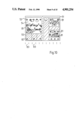
- FIGS. 16a and 16b show two preferred embodiments from which the choice and arrangement of the control patches can be seen.
- a printing process For influencing the colour appearance of coloured areas composed of severalseparation colours (e.g. cyan, magenta, yellow, black) in a printing process measuring devices are used, predominantly so-called densitometers and more rarely colorimeters (of the "spectral photometer” or "three-filter meter” type).
- the term "printing process” when used below should be understood to designate all reproduction processes which either produce a printed image on a substrate by means of a printing forme which is inked with an image (e.g. offset printing, gravure, letterpress) or areused as so-called pre-press proof processes as press proof substitutes in reproduction or which are non-impact processes, such as ink-jet printing, transfer thermography, electrophotoraphy and screen printing.
- FIG. 1 The way in which area is divided up in a typical printed sheet 51 which canbe produced using the aforementioned processes is sketched in FIG. 1.
- a print control strip 52 which contains test areas for process control, preferably by densitometric means.
- the subject located on the total formatarea of the printed sheet 51 consists here of eight pages of an illustratedwork, including both illustations 54 and text 55.
- a coloured area 56 which is here part of an illustration is emphasised particularly here. This coloured area--there could also be several such areas--is selected on the subject by the printer.
- the printer periodically examines the printed result, the actual sample 62 (FIG. 2) produced in each case and a target sample 61 which serves as a reference being compared as regards the colourappearance of the coloured area 56 to be influenced, this examination beingcarried out visually and optionally also using measuring techniques with the aid of the test areas on the print control strip 52. If no target sample is available the comparison is made using target values determined on the basis of past experience. Using the actual values determined on theactual sample 62 and the target samples the differences "actual value minustarget value" are formed and understood as a deviation in terms of regulation. In the case of densitometry these are density value differences, and in the case of colorimetry they are colorimetric difference values.
- regulating means are known in which any deviation can be converted fully automatically into a setting instruction for correction of the inking of the relevant separation colour. Interruption of the control circuit by the operating staff is both possible and sensible here, since the production process can also be greatly influenced by disruptions which cannot be determined using the chosen test areas. An example of this is the influence deriving from the damping solution in the offset process.
- test areas used for measuring differ very greatly from the corresponding values of the coloured area to be influenced as regards the percent dot area of the separation colours.
- the known regulating method only ensures that the appearance of the colours in the test area remains constant; this does not always necessarily apply to the coloured area to be influenced.
- the appearance of the colours in these control patches can indeed be kept constant; however, this does not necessarily also apply to the appearance of the colours of a light tone.
- the latter in fact depends not only upon the ink thickness which can be controlled by the solid control patches but also to a large extend upon production-contingent fluctuations in the percent dot area in the light tone range.
- One disadvantage of the known influencing methods is that the separation colours participating in the image sysnthesis are adjusted independently of one another. This can lead to the colour appearance perceived by an observer and in particular the hue of a coloured area considered critical for the acceptance of the product being drastically altered because the accurate grading of the quantities of separation colours applied which is necessary in order to arrive at this hue are not taken into account duringthe regulation process. If the aggregates of the separation colours applieddiffer as regards their regulation action the regulating process can even lead temporarily to an increase in the hue deviations, although the individual density deviations of the separation colours are all reduced.
- the U*-V* diagram belonging to the approximately subjectively equidistant colour space according to CIE-UCS-1964 is shown as an example in FIG. 3. It deals with a rectangular Cartesian system of co-ordinates with linear axes graduated on the same scale for the colorimetric co-ordinates U* and V*.
- the co-ordinate W* is plotted on an axis which is at right angles thereto and describes the brightness. All colours of the same hue lie on the same radius going out from the source in the U*-V* plane.
- the colour saturation increases as the distance from the source increases.
- the polar angle here designates the hue and theradius the saturation, the pole represents the neutral grey or white hue, also called the achromatic point.
- the invention takes as its starting point methods of influencing the colourappearance of a coloured area made up of at least three chromatic separation colours in a printing process on the basis of densitometric or colorimetric measurements in at least one test area in which the differences between actual and predetermined values are determined and used to influence the inking of the separation colours. Its object is to provide such a method in which the shortcomings of the prior art which have been referred to are avoided and an improved and in particular quicker means of influencing the colour appearance of the coloured area ina printing process is achieved.
- FIG. 4 shows a plane of equal brightness of the CIE-UCS-1964 colour space.
- the axes U* and V* known from FIG. 3 were shifted parallel so that the (for the moment unknown) target colour co-ordinates of the coloured area 56 which is to be influenced as regards its colour appearance now liein the source 0.
- the separation colour black is regulated separately according to the prior art.
- the density value difference of each chromatic separation colour is detected after multiplication by a scale factor (to be explained later with the aid of Table 1) as absolute amount (length) of a separation colour vector 72 the direction of which coincides with the appertaining separation colour direction 71.
- the vectorial addition of the separation colour vectors 72 points from the source O to the point P'; the vector OP is designated as sum vector 73.
- the point P' is the actual colour co-ordinates approximatedby means of vectorial auxiliary construction. By measuring with a colorimeter the actual colour co-ordinates are obtained directly, designated here by P".
- a printed product is produced, the pictures of which are produced by four-colour overprinting with suitably graded inking in the basic colours black, cyan, magenta and yellow.
- control patches with 80% dot area are also provided on the four printing formes as part areas for the purpose of densitometric measurement.
- the absolute amount of the sum vector OP at10.5 units indicates the approximate colour distance of the actual sample from the target sample without taking account of the brightness for a greytint composes of cyan, magenta and yellow (here designated as a shadow balance) with the percent dot areas C 72%, M 59%, Y 55% in the half-tone positive field in subjective units ⁇ E CIE-UCS-1964.
- the polar angle 342° designates the approximate direction of the colour shift whichhas occurred--here towards red violet.
- the colour shift indicated by the sum vector OP is broken down according tothe invention into a grey proportation which only affects brightness and a coloured proportion which relates predominantly to hue and saturation, which is chosen here so that it only relates to magenta and yellow.
- the coefficients of the vectors M and Y contained in parentheses are chosenso that the analysis of the parentheses carried out geometrically in accordance with FIG. 5 leads back to the source O, i.e. zero.
- the proportions can be used according to different strategies forcontrolling the press. For example, it might be decided initially not to balance out the density value differences corresponding to the grey proportion but first by appropriate ink fountain setting to carry our the corrections in the inking which relate empirically to the density value differences 0.26 for magenta and -0.06 for yellow. After this relatively minor intervention into the ink flows of the magenta and yellow printing units the original colour appearance of the nominally grey coloured area is restored to a perceptible but less distrubing brightness deviation.
- shadow balance which is produced by overprinting suitably graded percent dot areas of cyan, magenta, yellow and possibly also black, and also that in each case test areas printed with only one separation colour--for instance assembled in one print control strip--are available for densitometric measurement.
- the percent dot area of the film copies appertaining to the test areas should be chosen in the half-tone positive in the range of 40% to 80%, and the combination of cyan 75%, magenta 62% and yellow 60% belonging to a shadow balance and other similar gradations are preferred because under normal printing conditions in offset printing with triple overprint an approximately neutral, grey dark hue is produced which reacts very sensitively to the slightest fluctuations in the inking in one or more of the participating separation colours. Therefore a signalfunction is ascribed to such test areas; in the event of fluctuations in the printing process the alterations in the colour co-ordinates which can be measured there colorimetrically are always greater than in all the other coloured areas which are also composed of three chromatic separationcolours and have the same or a greater degree of brightness.
- the density value differences "actual value minus target value" of the chromatic separation colours are interpreted after multiplication by scale factors as absolute amounts of separation colour vectors 72 which here point from the source of a subjectively equidistant colour space in each case approximately in the region of the colour co-ordinates of the appertaining solid tone. In the general case they point from the colour co-ordinates of the coloured area to be influenced approximately to the target colour co-ordinates of the fully saturated separation colour.
- the colour space it is preferably a matter of the CIE-UCS-1964 system or the CIE-LUV system.
- the most favourable separation colour directions for the method according to the invention can be determined by the following process and sensible variants thereof:
- a coloured area which is constructed as a shadow balance is subjected to theprinting process during which the inking of the chromatic separation colours is systematically varied.
- a colorimeter is used to measure the colour co-ordinates of the balance, the full tones of the chromatic basic colours and those of their mixtures of the first order in several samples which deviate in a typical manner.
- the values of a target sample with an almost ideal grey shadow balance are used as target values and subtracted from the corresponding values for the actual samples; the result is plotted in an equal brightness plane of the selected colour space.
- FIG. 6 shows the result of such a test run in a diagram modelled on FIG. 5 in which the target colour co-ordinates of the almost ideal grey target sample lie in the source.
- the target colour co-ordinates of the basic and mixed colours lie for outside the diagram and are here marked simply as separation colour directions.
- the separationcolour direction M' is used instead of the direction M*.
- the end points A' to F' of the sum vectors are plotted in this diagram on the basis of the density value differences for cyan, magenta and yellow determined with a densitometer.
- D is the mean of the colour densities of the chromatic separation colours measured in the test area or areas.
- the percent dot area factor takes account of the fact that a measured alteration in the inking of a separation colour can certainly only be effective in so far as it is represented in proportion to the area in the relevant coloured area. Therefore the same production fluctuations work out lower by a factor of 2to 3 in a middle tone balance coloured area with C 28 M 21 Y 19 than in a shadow balance with C 72 M 57 Y 55, which corresponds to approximately 2.5times higher percent dot area.
- the same also applies to other coloured areas composed of a plurality of colours, including those which lie further away from the grey axis, so long as they are not darker than the shadow balance.
- the coloured areas 31-48 are chosen according to DIN 6169, F is the colour co-ordinates of the shadow balance.
- the colour co-ordinates of the target sample lie in the source, but only the colorimetric difference values are shown; the absolute amount of the shift is at maximum here. This observation was also made in the other actual samples evaluated for FIG. 6.
- the deviation of the shadow balance coloured area can therefore be designated as the upper limit for the corresponding values of all other coloured areas according to the absoluteamount, so long as the coloured areas are not darker than this balance coloured area.
- the polar angle of the deviation also applies to most othercoloured areas. Those coloured areas which predominantly contain only proportions of two chromatic separation colours or also the separation colours themselves constitute an exception here.
- the coloured areas 36, 38 and 42 break out of the direction trend.
- there shiftdirection can also be determined according to the vectorial auxiliary construction according to the invention from density value differences if it is borne in mind that one of the three scale factors must disappear since the related percent dot area is zero.
- the application of the scale factors calculated with the percent dot areas of the coloured area 36 C 0.55; M 0.39; Y 0.00 results after addition of the vecotrs in the point P'which approximates the deviation of the coloured area 36 with a satisfactory degree of accuracy.
- ⁇ W* represents the deviation of the brightness W* based on alterations in the inking of cyan, magenta and yellow, determined via the density value deviations ⁇ D C , ⁇ D M and ⁇ D Y in the appertaining monochrome 80% control patches.
- D B is the density value for black measured on a black control patch and ⁇ D B is the alteration thereof.
- the number triple ( ⁇ , ⁇ , ⁇ ) is chosen so that in each case one of the coefficients ⁇ , ⁇ , ⁇ is equal to 1 and in addition
- control or regulation can be carried out according to either of the breakdowns thus found. For example it may be decided that no intervention is to made at the moment in the inking of magenta on an offset press because the ink/water balance is considered critical here. Instead the deviation is corrected via cyan and yellow; deviations in brightness are accepted. In other cases the choice can be made according to one or more of the following criteria;
- the coloured proportion is composed of the two separation colour vectorsbetween which the sum vector OP lies.
- OP lies betweenthe directions "plus M” and "minus Y”; the coloured proportion composed of "plus M” and "minus Y” demonstrably fulfils criterion 1 geometrically.
- Thechoice of vectors of the coloured proportion can therefore also be made according to polar angle ranges for OP.
- the means for achieving the object according to the invention are set out above for the general case but are limited for the sake of clarity to the control or regulation of the colour appearance of a shadow balance coloured area to be produced in half-tone printing and to be influenced asregards its colour appearance with the aid of densitometric measurements ontest patches which are each printed with only one separation colour.
- the application of this teaching toi any coloured areas to be influenced and any test patches is already marked out by the splitting up of the scale factors in Table 1 into the percent dot area on the film copy or the printing forme of the coloured area and the calibration factor f which is based upon the test patch and dependent upon the colour density.
- any chromatic separation colours of which at least three are not the same hue are used for the image syntheses. If there are more than three separation colours of different hue there are any number of different breakdowns into a grey proportion and a coloured proportion. However, these are reduced to a few as soon as the coloured proportion is composed according to the invention of at most two chromatic separation colours.
- the method according to the invention can also be applied to the production of pre-press proofs or press proofs (according to a model as target sample or according to targetdensity values), to the setting-up process in the preparation of the production print according to an available press proof as target sample, apre-press proof or a previous production print and finally to other printing process operating in a comparable manner such as for example ink-jet printing, transfer thermography, electrophotography and screen printing, so long as the image synthesis is achieved by at least three chromatic colours (of differing hue) which can be influenced as regards inking.
- the inking is controlled in monochrome screened test patches
- the object of the invention is achieved by densitometric measurement on monochrome solid tone patches in offset printing, on three-colour over-printed half-tone patches, by densitometric formation of mean values from the subject and by colorimetry.
- preferred embodiments are set out in Examples 1 to 3 with which the method according to the invention can be carried out particularly favorably.
- the vectorial auxiliary construction is sufficient to enable the division of the sum vector according to the invention into a grey proportion and a coloured proportion composed of twoseparation colours to be carried out sensibly.
- a preferred composition of the coloured proportion (according to criterion 4) is produced from the two separation colour directions C*, M' and Y* flanking the respective point, and these should also be though of as being extended through the source.
- point A' is represented through Y and minus M', point B' through minus C and M, point C' through M' and minus C' etc.
- the further processing of the deviation using regulating techniques has already been described.
- control and regulating method according tothe invention can be carried out when measurements can only be made using control patches with a plurality of colours overprinted as test patches.
- a print control strip is provided whichcontains at least one shadow balance control patch in each area and also has for example solid tone patches for four to six colours (see example 3).
- the density values of cyan, magenta and yellow are measured with a densitometer in each shadow balance control field of an actual sample and and compared with those of a target sample or with target values from a preceding production. From the density value differences obtained
- the densitometric measurement in a shadow balance control patch is sufficiently accurate to facilitate the breakdownof the deviation calculated therefrom into a grey proportion which only affects brightness and a coloured proportion which is composed of at most two chromatic separation colours and the subsequent separate restoration of these proportions by control or regulating processes.
- the separation colour black is not taken into account, since it is not contained in the text area used, black can also be introduced in the general case into the overprint patch which was previously laid out in three colours. The result is a linear system of equations with four equations for four unknowns to be solved by analogy.
- measurements are made for example densitometrically on theprint samples on a fixed choice of test patches in the subject itself and the mean values of the density values thus obtained are calculated for thecyan, magenta, yellow and black settings of the densitometer.
- those image areas 81 in which many chromatic separation colours with a percent dot area in the range between 40% and 80% (on the film or on the printing forme) occur, such as for example the three-colour mix of dark grey, brown and olive green tones, are chosen as test patches.
- the image areas should be chosen so that the percent dot areas averaged over these image areas lie in the aforesaidrange for each separation colour.
- the density measurement on the fixed image areas can be carried out for example by an automatic densitometer which can be programmed to move in the X and Y directions, by measurement by hand or by so-called "on-line measurement" at at least one position over the machine width.
- the restriction of the measurement to specific image areas 81 can be achieved by a suitable choice of measuring positionsand/or by timed measurement synchronised with the printing process.
- the mean density values for cyan, magenta, yellow and black obtained on the target sample are regarded as target values, possibly separated according to printing areas 83 (measuring positions over the machine width).
- the density value differences occurring during production are used after recalculation for control by hand or automatic regulation using the methodaccording to the invention.
- the necessary determining of the density values, which would have resulted from the individual printing of the separation colours, takes place according to the same method as has already been described for the measurement on a shadow balance control field made up of three colours.
- the density value differences ⁇ D' between the measured actual values and the target values of a target sample were recalculated as before usinga linear equation system into density value differences ⁇ D for cyan, magenta, yellow and black which would have been produced on monochrome prints. From the mean value for the densities of cyan, magenta and yellow the following scale factors were produced according to equation (1): 0.71 ⁇ 106 for cyan, 0.57 ⁇ 106 for magenta and 0.55 ⁇ 106 for yellow; these apply to the colour appearance of a shadow balance coloured area.
- the target sample and the actual samples of the current production are scanned optically as a whole. Only the analog signals belonging to the test patches on the subject or on control patches are processed further to density values and density value differences.
- Example B In the event that control patches composed of a plurality of colours are present, the method continues as in Example B; if measurement is carried out in the subject itself the method is continued as in Example C.
- measurement can also be carried out using a colorimeter.
- the same criteria apply here for the choice of image areas, but in addition one or more points should be chosen on the total format area of the printed sheet 51 on which the separation colour black is predominantly represented. These can be dark grey half-tone patches, so-called technical half-tone grounds in tables, text areas (black image area 82 in FIG. 10) or similar patches.
- the field of measurement aperture of the colorimeter should have a minimum size of approximately 10 ⁇ 10 mm since only in this way is it possibleto avoid small positioning errors which have a serious effect on the result.
- the mean is taken separately over the chromatic image areas and the predominantly or exclusively black image areas, only the brightness co-ordinate being necessary for the latter. This results for example in the co-ordinates U*, V* and W* in the CIE-UCS-1964 system being obtained for the chromatic image areas 81 and W B * for the predominantly blackimage areas 82.
- the brightness deviation of the black image areas which is obtained thereby, e.g. ⁇ W B * is used directly and in accordancewith the prior art to control or regulate the inking of the separation colour black.
- the deviation of the chromatic image areas expressed by colorimetric difference values is represented according to the invention as the sum of a grey proportion which only affects brightness and a coloured proportion relating to at most two chromatic separation colours. The proportions are then balanced out or regulated separately.
- the method will be demonstrated below using the example of the CIE-UCS-1964system for a shadow balance coloured area.
- the measured colorimetric difference values be ⁇ U*, ⁇ V* and ⁇ W 1 * for the chromatic image areas and ⁇ W B * for the black image areas.
- the coefficient k depends upon the reprophotographic image synthesis. It is small when no under colour reduction and no grey component replacement (also called Unbuntopathic, achromatic synthesis or complementary colour reduction) has taken place; k is near 1 when the image components which add up to grey in the chromatic separation colours are replaced by the separation colour black.
- the respective values can be determined by print trials using the relevant reproduction techniques.
- the point P which is constructed from the measured colorimetric difference values ⁇ U* and ⁇ V* is marked in the ⁇ U*- ⁇ V* diagram according to FIG. 12.
- These can be represented as a linear combination of the unit vectors 1 u and 1 v in the directions U* and V* as follows: ##EQU5##
- the deviation from the starting point O is expressed by the sum vector OP. According to the invention this can be expressed as the sum of two proportions which are to be processed differently using regulating techniques:
- Equation (17) designates the grey proportion which only affects brightness; there then remains the coloured proportion made up of at most two colours.
- a decision can be made according to one of the criteria set out above as to which two colours areused to constitute (and balance out) the coloured proportion and which factor g is chosen.
- a preferred choice is one in which the fourth of the aforementioned criteria is fulfilled.
- the alteration in brightness calculated from the two proportions thus determined should correspond to the alteration ⁇ W* which remains for the chromatic image areas after deduction of the black proportion k ⁇ W B *.
- the calculation of the alteration in brightness for the proportions requires a single print trial in which the inking of the separation colours cyan, magenta and yellow is increased individually in each case by the increments b C 1 C , b M 1 M or b Y 1 Y which are to be determined colorimetrically, and reductions in the brightness by ⁇ W C *, ⁇ W M * or ⁇ W Y * result from these.
- the alteration in brightness can now be calculated according to the formula ##EQU6##It can be seen from the same print trial which alteration of the setting for the inking of a separation colour corresponds to the appertaining unitvector in the ⁇ U*- ⁇ V* diagram.
- This relates to a densitometer which is to be positioned and operated by hand and used in particular for controlling printing processes, not only during make-ready and colour matching but also during production printing.
- test patches on which the measurement is carried out e.g. monochrome control patches or control patches laid out in a plurality of colours as balance, and a "coloured area to be influenced" in which the colour appearance is considered decisive for the usefulness of the product or as a guarantee of the correct colour rendering.
- the coloured area to be influenced must be knownat least approximately as regards its colorimetric co-ordinates of hue and saturation as well as its percent dot areas in the chromatic separation colours. It is not necessary for it actually to be present on the subject to be printed. Thus printing can be controlled in such a way that the colour appearance of a shadow balance coloured area (not contained in the subject) would remain constant.
- FIG. 13 shows the signal processing path of such a densitometer according to the invention; the mechanical, optical and other electronic components are not shown.
- the light from the light source 1 which is reflected by the test patch of the target or actual sample is detected in the sensor 2.
- the signal which is initially present in analog form is brought into digital form, preferably 16 bit technology, in an analog/digital converter 3, and converted in unit4 to actual values.
- the mean is also taken here, if the corresponding inputinstruction a from unit 5 is present.
- the density values b located in the target value store in unit 5 are either fed in by the user or stored from a target sample; they are subtracted from the actual values in unit 6. If the measurements did not take place on monochrome image areas or control patches, the matrix calculation of the individual colour densities is carried out in unit 7 from the total colour densities.
- the sum vector OP is calculated in unit 8 if the input data c "Target values of the saturated chromatic separation colours" and "Target colour co-ordinates and percent dot area of the coloured area to be controlled" are present from unit 5.
- the sum vector OP which is not broken down and preferably also the separation colour vectors, e.g. C, M, Y, are represented in an output unit 11 graphically (preferably in colour) on a screen or on an X-Y recorder, e.g. as shown in FIGS. 3 and 5.
- the numeric or verbal output of the density value differences of the separation colours can be made, e.g. cyan, magenta, yellow, black, the absolute amount of the sum vector, e.g.
- the hue of the shift e.g. reddish, greenish, yellow-reddish or as a polar angle.
- the operator can be warned by the boundary value indicator as soon as the amount of the sum vector OP exceeds a fixed value or the polar angle is located in a range which is tobe regarded as critical, e.g. green cast in the printing of skin tones.
- the operator can also orient himself by magnitude and direction of the deviation for this coloured area.
- the calculation of the grey proportion which only affects brightness and the coloured proportion which relates at most to two chromatic separation colours takes place in unit 10 if the input data d are available there from unit 5 regarding the separation colours of the coloured proportion or one of the aforementioned criteria for choice.
- the output of the control recommendation in density value units, or already converted into the respective setting is carried out by unit 12 while the values for the chromatic separation colours and black are are sent as output data separately according to "colour cast" and "brightness". This can be achieved in alphanumeric or graphic form on the output unit 11.
- This relates to apparatus for regulating the colour appearance of printing or similar products after adjustment of the inking of the separation colours on the basis of measurements of the degree of reflectance of test patches on the products.
- the apparatus is shown in FIG. 14 according to the model of FIG. 13 in the form of a signal flow diagram.
- the mechanical, optical and other electronic components are not shown.
- the signal path up to and including the analog/digital converter 3 is as described in Example 1.
- the signals measured either on-line in the production machine or off-line on an actualsample are converted in unit 4 into actual values for the density; if thereis an appropriate instruction c from unit 5, mean values are formed for thedensity values of a plurality of test patches, e.g. image areas, or successive actual samples measured on-line.
- the appertaining density values or their mean values are preferably calculated in each colour zone and finally after evaluation are converted into setting instructions.
- regulating factor is the conversion factor between deviation and setting correction. Regulation in which the regulating factor of the coloured proportion is chosen so that it is larger than that of the grey proportion is preferred in terms of theinvention.
- the setting instructions are passed to the setting motors 13 of the ink fountain.
- the success of the setting operation is checked densitometrically on an actual sample which is taken later, resulting if necessary in a further regulating process etc.
- Example 2 Whilst the apparatus previously described under Example 2 makes it possibleto regulate the colour appearance of the coloured area to be influenced by means of densitometric measurement, it can also be immediately inferred from the description how a similarly operating apparatus can be constructed which serves for colorimetry.
- the colorimetric measurement canbe advantageously carried out on multi-coloured control patches and in particular on balance control patches or also directly on one or more chromatic image areas serving as test patches and separately on black image areas, over which an average is then to be taken.
- the basic layout of the signal flow plan according to FIG. 14 is retained and the few alterations are marked in FIG. 15.
- the colorimetric co-ordinates are calculated from the measured signals in unit 4, the colorimetric difference values are formed in unit 6.
- Unit 8 calculates the data for alphanumeric and/or graphic output on the output unit 11, if the colour co-ordinates of the fully saturated separation colours and the target colour co-ordinates of the coloured area to be influenced are fed in via the input c from unit 5.
- the correction of the brightness value determinedon chromatic image areas is also carried out in unit 8 with the alteration which was determined on the black image areas. Accordingly the output unit11 displays not only the amount and direction of the sum vector OP but alsothe alterations in the brightness of the chromatic image areas and the image areas serving for control of the separation colour black.
- This print control strip is preferably so constructed that in each print zone, i.e. every 30 to 40 mm, there is a shadow balancecontrol patch which has percent dot areas graded according to a reprophotographic grey specification appropriate for usual printing conditions on the copy. Examples are C 72, M 57, Y 55 or C 75, M 62, Y 60 for positive copies in offset printing on art paper.
- FIGS. 16a and 16b show two preferred examples from which the choice and arrangement of the control patches can be seen. They show the print control strips which are produced at the same time by the apparatus according to the above definition.
- control patch 21 of 5 ⁇ 5 mm 2 constructed as a shadow balance in each zone, here assumed to be 30 mm
- a further control patch 22 constructed as a middle-tone balance.
- the image rendering in the middle-tone range can be influenced particularly well.
- a half-tone patch 23 forblack with 80% dot area As well as 21 in every second zone there is a half-tone patch 23 forblack with 80% dot area. The latter makes the inking of black controllable,and the measurement of the inking of the chromatic separation colours takesplace in the control patches 21 and 22.
- control patch 21 and 22in each zone here also assumed to be 30 mm.
- half-tone patches 23 with 80% dot area for all four separation colours in every second zone.
- copy control patches 25 and line screen patch pairs 26 for all separation colours are provided; they are repeated approximately every 9 zones.
- control patches shown in FIGS. 16a and 16b can of course be varied, complemented or have their repeat period changed, so long as a half-tone control patch composed of the chromatic basic separation colours can be measured in each zone and a half-tone or solid tone patch for black can also be measured in every second or third zone.
- the different forms of apparatus described above are suitable not only for screen printing but also for those printing processes which work with screened copies.
- the apparatus according to Example 3 could also serve forcompletely screenless methods if 21, 22, 23, 24 are constructed as half-tone patches on condition that instead of the value for the percent dot area the mathematical value given in Equation (12) is used.
Landscapes
- Engineering & Computer Science (AREA)
- Quality & Reliability (AREA)
- Spectrometry And Color Measurement (AREA)
- Inking, Control Or Cleaning Of Printing Machines (AREA)
- Printing Methods (AREA)
- Color, Gradation (AREA)
Applications Claiming Priority (2)
| Application Number | Priority Date | Filing Date | Title |
|---|---|---|---|
| DE19863626423 DE3626423A1 (de) | 1986-08-05 | 1986-08-05 | Verfahren und vorrichtung zur beeinflussung der farblichen erscheinung einer farbflaeche bei einem druckvorgang |
| DE3626423 | 1986-08-05 |
Publications (1)
| Publication Number | Publication Date |
|---|---|
| US4901254A true US4901254A (en) | 1990-02-13 |
Family
ID=6306693
Family Applications (1)
| Application Number | Title | Priority Date | Filing Date |
|---|---|---|---|
| US07/073,444 Expired - Fee Related US4901254A (en) | 1986-08-05 | 1987-07-14 | Method and apparatus for influencing the colour appearance of a colored area in a printing process |
Country Status (4)
| Country | Link |
|---|---|
| US (1) | US4901254A (de) |
| EP (2) | EP0255586B1 (de) |
| AT (2) | ATE73392T1 (de) |
| DE (3) | DE3626423A1 (de) |
Cited By (30)
| Publication number | Priority date | Publication date | Assignee | Title |
|---|---|---|---|---|
| US5068810A (en) * | 1989-07-14 | 1991-11-26 | Gretag Aktiengesellschaft | Process for the determination of colorimetric differences between two screen pattern fields printed by a printing machine and process for the color control or ink regulation of the print of a printing machine |
| US5072472A (en) * | 1987-12-07 | 1991-12-17 | Passap Knitting Machines, Inc. | Continuous process for dyeing a textile thread, and installation for the implementation of this process |
| US5089977A (en) * | 1989-02-10 | 1992-02-18 | Heidelberger Druckmaschinen Ag | Process for controlling the inking of printed products and apparatus for performing the process |
| US5149960A (en) * | 1991-07-03 | 1992-09-22 | R. R. Donnelley & Sons Company | Method of converting scanner signals into colorimetric signals |
| US5218555A (en) * | 1989-11-27 | 1993-06-08 | Toyo Boseki Kabushiki Kaisha | Method for judging a color difference using rules fuzzy inference and apparatus therefor |
| US5224421A (en) * | 1992-04-28 | 1993-07-06 | Heidelberg Harris, Inc. | Method for color adjustment and control in a printing press |
| US5258925A (en) * | 1990-02-22 | 1993-11-02 | Man Roland Druckmaschinen Ag | Printing process diagnostic method and system for a rotary printing press, using diffuse reflection of solid-print and half-tone fields |
| US5317425A (en) * | 1992-02-10 | 1994-05-31 | Eastman Kodak Company | Technique for use in conjunction with an imaging system for providing an appearance match between two images and for calibrating the system thereto |
| US5448502A (en) * | 1991-06-20 | 1995-09-05 | Matsushita Electric Industrial Co., Ltd. | Devices for judging image on the basis of gray world assumption, discriminating color chart, deducing light source and regulating color |
| US5696890A (en) * | 1993-10-16 | 1997-12-09 | Heidelberger Druckmaschinen Ag | Method of register regulation and printing control element for determining register deviations in multicolor printing |
| US5740076A (en) * | 1995-11-30 | 1998-04-14 | Candela, Ltd. | System for describing a color gamut in a graphical data processing system |
| US6262808B1 (en) * | 1992-03-30 | 2001-07-17 | Ciba Specialty Chemiclas Corporation | Multicolor printing process, especially a multicolor grid screen printing process for textile substrates |
| EP1080892A3 (de) * | 1999-09-06 | 2001-09-05 | Komori Corporation | Color-Management-Verfahren und -Vorrichtung für eine Druckmaschine |
| US20020154326A1 (en) * | 2001-04-06 | 2002-10-24 | Okinori Tsuchiya | Image processing method and apparatus |
| US20030066446A1 (en) * | 2001-10-10 | 2003-04-10 | Dainippon Screen Mfg. Co., Ltd. | Printing apparatus |
| US20030066447A1 (en) * | 2001-10-10 | 2003-04-10 | Dainippon Screen Mfg. Co., Ltd. | Method of presetting ink |
| US20030070570A1 (en) * | 2001-10-15 | 2003-04-17 | Takaharu Yamamoto | Printing apparatus |
| US20030161016A1 (en) * | 2002-02-28 | 2003-08-28 | Eastman Kodak Company | Method of decoding data encoded in a monochrome medium |
| US20040036918A1 (en) * | 1990-02-05 | 2004-02-26 | Creo Il Ltd. | Database functions in a closed loop ceps-press systems |
| EP1156667A3 (de) * | 2000-05-17 | 2004-05-06 | Komori Corporation | Color-Management-Verfahren und -Vorrichtung für eine Druckmaschine |
| EP0495563B2 (de) † | 1991-01-15 | 2004-09-29 | Creo IL.Ltd. | Rechnergesteuertes Druckgerät und Technik |
| WO2005082620A1 (de) * | 2004-02-26 | 2005-09-09 | Man Roland Druckmaschinen Ag | Verfahren zur farbregelung an druckmaschinen |
| US20080127849A1 (en) * | 2006-11-30 | 2008-06-05 | Hiroshi Sugimoto | Method Of Controlling Quality Of Printed Images Of Color Printing Press And Apparatus For Controlling Quality Of Printed Images |
| US20090315963A1 (en) * | 2008-06-18 | 2009-12-24 | Canon Kabushiki Kaisha | Ink jet printing apparatus and method for determining drying condition for print image |
| US20120076402A1 (en) * | 2007-05-15 | 2012-03-29 | Vision Interface Technologies, LLC | Rich Color Transition Curve Tracking Method |
| US20150068418A1 (en) * | 2013-09-10 | 2015-03-12 | Manroland Web Systems Gmbh | Method for printing on a substrate |
| WO2016047378A1 (ja) * | 2014-09-26 | 2016-03-31 | 富士フイルム株式会社 | 測定位置提示方法及び測定位置提示ガイドの製造方法及び印刷物の測定方法及び印刷物の測定位置決定方法及び印刷物の測定位置決定装置 |
| JP2016070697A (ja) * | 2014-09-26 | 2016-05-09 | 富士フイルム株式会社 | 測定位置提示方法及び測定位置提示ガイドの製造方法並びに印刷物の測定方法 |
| JP2016070699A (ja) * | 2014-09-26 | 2016-05-09 | 富士フイルム株式会社 | 印刷物の測定位置決定方法及び装置並びに測定方法 |
| US9536322B1 (en) | 2007-05-15 | 2017-01-03 | Peter Harmon Smith | Implementation of multi-camera tracking applications using rich color transition curve target sequences |
Families Citing this family (15)
| Publication number | Priority date | Publication date | Assignee | Title |
|---|---|---|---|---|
| DE3643721A1 (de) * | 1986-12-20 | 1988-06-30 | Heidelberger Druckmasch Ag | Druckkontrollstreifen |
| DE3862409D1 (de) * | 1987-02-23 | 1991-05-23 | Gretag Ag | Verfahren zur fortdruckregelung der farbgebung beim tief- oder flexodruck und entsprechende druckmaschine. |
| DE3812099C2 (de) * | 1988-04-12 | 1995-01-26 | Heidelberger Druckmasch Ag | Verfahren zur Farbsteuerung einer Offsetdruckmaschine |
| DE3829341A1 (de) * | 1988-08-30 | 1990-03-08 | Roland Man Druckmasch | Datenerfassung fuer farbregelanlagen |
| DE3830731A1 (de) * | 1988-09-09 | 1990-03-22 | Heidelberger Druckmasch Ag | Vorrichtung zur farbmessung |
| DE3942254A1 (de) * | 1989-12-21 | 1991-07-04 | Krzyminski Harald | Druckkontrollstreifen |
| DE4104537C2 (de) * | 1991-02-14 | 1999-05-12 | Roland Man Druckmasch | Verfahren zur Steuerung einer Farbführung einer Offset-Druckmaschine |
| DE4240077C2 (de) * | 1992-11-28 | 1997-01-16 | Heidelberger Druckmasch Ag | Verfahren zur zonalen Steuerung/Regelung der Farbführung in einer Druckmaschine |
| DE4335229C2 (de) * | 1993-10-15 | 1998-07-16 | Heidelberger Druckmasch Ag | Verfahren zum Erzeugen von auf einer Offsetdruckmaschine hergestellten Farbmustern |
| DE4402784C2 (de) * | 1994-01-31 | 2001-05-31 | Wifag Maschf | Messfeldgruppe und Verfahren zur Qualitätsdatenerfassung unter Verwendung der Messfeldgruppe |
| DE4402828C2 (de) * | 1994-01-31 | 2001-07-12 | Wifag Maschf | Messfeldgruppe und Verfahren zur Qualitätsdatenerfassung unter Verwendung der Messfeldgruppe |
| DE19511076C1 (de) * | 1995-03-25 | 1996-05-23 | Roland Man Druckmasch | Verfahren zum Feststellen von Farbverschmutzungen beim Herstellen mehrfarbiger Druckexemplare auf Druckmaschinen |
| DE19515499C2 (de) * | 1995-04-27 | 1997-03-06 | Heidelberger Druckmasch Ag | Verfahren zur simultanen Mehrfarbregelung beim Drucken |
| IT1284432B1 (it) * | 1996-03-22 | 1998-05-21 | De La Rue Giori Sa | Procedimento di controllo automatico della qualita' di stampa di un'immagine policroma |
| CN120238615A (zh) * | 2025-06-03 | 2025-07-01 | 北京弘浩千瑞科技有限公司 | 一种胶印机的色彩还原控制方法及系统 |
Citations (7)
| Publication number | Priority date | Publication date | Assignee | Title |
|---|---|---|---|---|
| US4310248A (en) * | 1980-04-24 | 1982-01-12 | Meredith Nolan J | Color control system |
| US4414635A (en) * | 1978-11-28 | 1983-11-08 | Dr.-Ing. Rudolf Hell Gmbh | Method and circuit for recognition of colors |
| US4623973A (en) * | 1983-12-14 | 1986-11-18 | Dr. Ing. Rudolf Hell Gmbh | Method and apparatus for the recognition of hues and colors |
| US4649502A (en) * | 1983-11-04 | 1987-03-10 | Gretag Aktiengesellschaft | Process and apparatus for evaluating printing quality and for regulating the ink feed controls in an offset printing machine |
| US4688178A (en) * | 1985-09-06 | 1987-08-18 | Burlington Industries, Inc. | Method and apparatus for inventory control to optimize usage of colored fabric |
| US4706206A (en) * | 1983-09-20 | 1987-11-10 | Kollmorgen Technologies Corporation | Color printing control using halftone control areas |
| US4717954A (en) * | 1983-05-10 | 1988-01-05 | Toppan Printing Co., Ltd. | Method and apparatus using a conversion table based on pre-printed color charts for determining half-tone dot percents required to reproduce the color of a color specimen |
Family Cites Families (4)
| Publication number | Priority date | Publication date | Assignee | Title |
|---|---|---|---|---|
| US4256131A (en) * | 1976-07-14 | 1981-03-17 | Sentrol Systems Ltd. | Feedback color control system |
| DE3007421A1 (de) * | 1980-02-27 | 1981-09-03 | Windmöller & Hölscher, 4540 Lengerich | Verfahren zur herstellung eines vorlagengetreuen farbengemisches, insbesondere einer farbe eines mehrfarbendruckes |
| DE3687074D1 (de) * | 1985-03-21 | 1992-12-17 | Felix Brunner | Verfahren, regelvorrichtung und hilfsmittel zur erzielung eines gleichfoermigen druckresultats an einer autotypisch arbeitenden mehrfarbenoffsetdruckmaschine. |
| GB0227842D0 (en) * | 2002-11-29 | 2003-01-08 | Rolls Royce Plc | Sealing Arrangement |
-
1986
- 1986-08-05 DE DE19863626423 patent/DE3626423A1/de not_active Withdrawn
-
1987
- 1987-06-12 EP EP87108516A patent/EP0255586B1/de not_active Expired - Lifetime
- 1987-06-12 DE DE8787108516T patent/DE3777277D1/de not_active Expired - Fee Related
- 1987-06-12 AT AT87108516T patent/ATE73392T1/de active
- 1987-07-14 US US07/073,444 patent/US4901254A/en not_active Expired - Fee Related
- 1987-07-31 AT AT87111135T patent/ATE88414T1/de not_active IP Right Cessation
- 1987-07-31 EP EP87111135A patent/EP0255924B1/de not_active Expired - Lifetime
- 1987-07-31 DE DE8787111135T patent/DE3785510D1/de not_active Expired - Fee Related
Patent Citations (7)
| Publication number | Priority date | Publication date | Assignee | Title |
|---|---|---|---|---|
| US4414635A (en) * | 1978-11-28 | 1983-11-08 | Dr.-Ing. Rudolf Hell Gmbh | Method and circuit for recognition of colors |
| US4310248A (en) * | 1980-04-24 | 1982-01-12 | Meredith Nolan J | Color control system |
| US4717954A (en) * | 1983-05-10 | 1988-01-05 | Toppan Printing Co., Ltd. | Method and apparatus using a conversion table based on pre-printed color charts for determining half-tone dot percents required to reproduce the color of a color specimen |
| US4706206A (en) * | 1983-09-20 | 1987-11-10 | Kollmorgen Technologies Corporation | Color printing control using halftone control areas |
| US4649502A (en) * | 1983-11-04 | 1987-03-10 | Gretag Aktiengesellschaft | Process and apparatus for evaluating printing quality and for regulating the ink feed controls in an offset printing machine |
| US4623973A (en) * | 1983-12-14 | 1986-11-18 | Dr. Ing. Rudolf Hell Gmbh | Method and apparatus for the recognition of hues and colors |
| US4688178A (en) * | 1985-09-06 | 1987-08-18 | Burlington Industries, Inc. | Method and apparatus for inventory control to optimize usage of colored fabric |
Cited By (45)
| Publication number | Priority date | Publication date | Assignee | Title |
|---|---|---|---|---|
| US5072472A (en) * | 1987-12-07 | 1991-12-17 | Passap Knitting Machines, Inc. | Continuous process for dyeing a textile thread, and installation for the implementation of this process |
| US5089977A (en) * | 1989-02-10 | 1992-02-18 | Heidelberger Druckmaschinen Ag | Process for controlling the inking of printed products and apparatus for performing the process |
| US5068810A (en) * | 1989-07-14 | 1991-11-26 | Gretag Aktiengesellschaft | Process for the determination of colorimetric differences between two screen pattern fields printed by a printing machine and process for the color control or ink regulation of the print of a printing machine |
| US5218555A (en) * | 1989-11-27 | 1993-06-08 | Toyo Boseki Kabushiki Kaisha | Method for judging a color difference using rules fuzzy inference and apparatus therefor |
| US6856424B2 (en) | 1990-02-05 | 2005-02-15 | Creo Il. Ltd. | Closed loop ceps-press control systems |
| US20040079253A1 (en) * | 1990-02-05 | 2004-04-29 | Creo Il Ltd. | Closed loop ceps-press control systems |
| US20040036918A1 (en) * | 1990-02-05 | 2004-02-26 | Creo Il Ltd. | Database functions in a closed loop ceps-press systems |
| US6856419B2 (en) | 1990-02-05 | 2005-02-15 | Creo Il Ltd | Database functions in a closed loop ceps-press systems |
| US5258925A (en) * | 1990-02-22 | 1993-11-02 | Man Roland Druckmaschinen Ag | Printing process diagnostic method and system for a rotary printing press, using diffuse reflection of solid-print and half-tone fields |
| EP0495563B2 (de) † | 1991-01-15 | 2004-09-29 | Creo IL.Ltd. | Rechnergesteuertes Druckgerät und Technik |
| US5448502A (en) * | 1991-06-20 | 1995-09-05 | Matsushita Electric Industrial Co., Ltd. | Devices for judging image on the basis of gray world assumption, discriminating color chart, deducing light source and regulating color |
| US5149960A (en) * | 1991-07-03 | 1992-09-22 | R. R. Donnelley & Sons Company | Method of converting scanner signals into colorimetric signals |
| US5317425A (en) * | 1992-02-10 | 1994-05-31 | Eastman Kodak Company | Technique for use in conjunction with an imaging system for providing an appearance match between two images and for calibrating the system thereto |
| US5333069A (en) * | 1992-02-10 | 1994-07-26 | Eastman Kodak Company | Technique for use in conjunction with an imaging system for providing an appearance match between two images and for calibrating the system thereto |
| EP0556133A3 (en) * | 1992-02-10 | 1995-10-11 | Eastman Kodak Co | A technique for use in conjunction with an imaging system for providing an appearance match between two images and for calibrating the system thereto |
| US6262808B1 (en) * | 1992-03-30 | 2001-07-17 | Ciba Specialty Chemiclas Corporation | Multicolor printing process, especially a multicolor grid screen printing process for textile substrates |
| US5224421A (en) * | 1992-04-28 | 1993-07-06 | Heidelberg Harris, Inc. | Method for color adjustment and control in a printing press |
| US5696890A (en) * | 1993-10-16 | 1997-12-09 | Heidelberger Druckmaschinen Ag | Method of register regulation and printing control element for determining register deviations in multicolor printing |
| US5740076A (en) * | 1995-11-30 | 1998-04-14 | Candela, Ltd. | System for describing a color gamut in a graphical data processing system |
| US7031022B1 (en) | 1999-09-06 | 2006-04-18 | Komori Corporation | Color management method and apparatus for printing press |
| EP1080892A3 (de) * | 1999-09-06 | 2001-09-05 | Komori Corporation | Color-Management-Verfahren und -Vorrichtung für eine Druckmaschine |
| EP1156667A3 (de) * | 2000-05-17 | 2004-05-06 | Komori Corporation | Color-Management-Verfahren und -Vorrichtung für eine Druckmaschine |
| US20020154326A1 (en) * | 2001-04-06 | 2002-10-24 | Okinori Tsuchiya | Image processing method and apparatus |
| US7312891B2 (en) * | 2001-04-06 | 2007-12-25 | Canon Kabushiki Kaisha | Image processing method and apparatus |
| US20030066446A1 (en) * | 2001-10-10 | 2003-04-10 | Dainippon Screen Mfg. Co., Ltd. | Printing apparatus |
| US6732645B2 (en) * | 2001-10-10 | 2004-05-11 | Dainippon Screen Mfg., Co., Ltd. | Method of presetting ink |
| US20030066447A1 (en) * | 2001-10-10 | 2003-04-10 | Dainippon Screen Mfg. Co., Ltd. | Method of presetting ink |
| US20030070570A1 (en) * | 2001-10-15 | 2003-04-17 | Takaharu Yamamoto | Printing apparatus |
| US6792863B2 (en) * | 2001-10-15 | 2004-09-21 | Dainippon Screen Mfg Co., Ltd. | Printing apparatus for automatically controlling ink supply device |
| US20030161016A1 (en) * | 2002-02-28 | 2003-08-28 | Eastman Kodak Company | Method of decoding data encoded in a monochrome medium |
| US7177476B2 (en) * | 2002-02-28 | 2007-02-13 | Eastman Kodak Company | Method of decoding data encoded in a monochrome medium |
| US20070188778A1 (en) * | 2004-02-26 | 2007-08-16 | Man Roland Druckmaschinen Ag | Method for controlling color on printing machines |
| CN100436130C (zh) * | 2004-02-26 | 2008-11-26 | 曼·罗兰·德鲁克马辛伦公司 | 在印刷机上进行颜色调节的方法 |
| WO2005082620A1 (de) * | 2004-02-26 | 2005-09-09 | Man Roland Druckmaschinen Ag | Verfahren zur farbregelung an druckmaschinen |
| US20080127849A1 (en) * | 2006-11-30 | 2008-06-05 | Hiroshi Sugimoto | Method Of Controlling Quality Of Printed Images Of Color Printing Press And Apparatus For Controlling Quality Of Printed Images |
| US9536322B1 (en) | 2007-05-15 | 2017-01-03 | Peter Harmon Smith | Implementation of multi-camera tracking applications using rich color transition curve target sequences |
| US20120076402A1 (en) * | 2007-05-15 | 2012-03-29 | Vision Interface Technologies, LLC | Rich Color Transition Curve Tracking Method |
| US8526717B2 (en) * | 2007-05-15 | 2013-09-03 | Vision Interface Technologies, LLC | Rich color transition curve tracking method |
| US20090315963A1 (en) * | 2008-06-18 | 2009-12-24 | Canon Kabushiki Kaisha | Ink jet printing apparatus and method for determining drying condition for print image |
| US20150068418A1 (en) * | 2013-09-10 | 2015-03-12 | Manroland Web Systems Gmbh | Method for printing on a substrate |
| US9623695B2 (en) * | 2013-09-10 | 2017-04-18 | Manroland Web Systems Gmbh | Method for printing on a substrate |
| WO2016047378A1 (ja) * | 2014-09-26 | 2016-03-31 | 富士フイルム株式会社 | 測定位置提示方法及び測定位置提示ガイドの製造方法及び印刷物の測定方法及び印刷物の測定位置決定方法及び印刷物の測定位置決定装置 |
| JP2016070697A (ja) * | 2014-09-26 | 2016-05-09 | 富士フイルム株式会社 | 測定位置提示方法及び測定位置提示ガイドの製造方法並びに印刷物の測定方法 |
| JP2016070699A (ja) * | 2014-09-26 | 2016-05-09 | 富士フイルム株式会社 | 印刷物の測定位置決定方法及び装置並びに測定方法 |
| US9937707B2 (en) | 2014-09-26 | 2018-04-10 | Fujifilm Corporation | Method of presenting measurement position, method of manufacturing measurement position presentation guide, method of measuring print material, method of determining measurement position of print material, and device for determining measurement position of print material |
Also Published As
| Publication number | Publication date |
|---|---|
| EP0255924A2 (de) | 1988-02-17 |
| EP0255586B1 (de) | 1992-03-11 |
| DE3777277D1 (de) | 1992-04-16 |
| DE3626423A1 (de) | 1988-02-11 |
| EP0255586A2 (de) | 1988-02-10 |
| ATE88414T1 (de) | 1993-05-15 |
| DE3785510D1 (de) | 1993-05-27 |
| EP0255924A3 (en) | 1990-05-02 |
| EP0255586A3 (en) | 1988-12-07 |
| EP0255924B1 (de) | 1993-04-21 |
| ATE73392T1 (de) | 1992-03-15 |
Similar Documents
| Publication | Publication Date | Title |
|---|---|---|
| AU2001278064B2 (en) | Spectral color control method | |
| US6041708A (en) | Process and apparatus for controlling the inking process in a printing machine | |
| US5182721A (en) | Process and apparatus for controlling the inking process in a printing machine | |
| US5530656A (en) | Method for controlling the ink feed of a printing machine for half-tone printing | |
| US4852485A (en) | Method of operating an autotypical color offset printing machine | |
| EP0136542B1 (de) | Verfahren zum Steuerung des Farbendruckes, mit Verwendung von Halbton-Kontrollflächen | |
| US4310248A (en) | Color control system | |
| US5841955A (en) | Control system for a printing press | |
| AU2001278064A1 (en) | Spectral color control method | |
| CA2784206C (en) | Method for controlling multicolor print quality | |
| JPH0522580B2 (de) | ||
| CA2012050C (en) | Process for the control of the inking of a printing press with limitation of the layer thickness and of the tonal-value increase | |
| US5761327A (en) | Group of measured fields for determining color data of a printed product | |
| US5602970A (en) | Process for setting the halftone dot sizes for a rotary offset printing machine | |
| US20050105111A1 (en) | Color quality assessment and color control during color reproduction | |
| JPS61248748A (ja) | オートタイプ式作動型の多色オフセツト印刷機により均等な印刷結果を達成する方法および単色ストリツプセツト | |
| US4309496A (en) | Method for optimization of image reproduction processes | |
| US6262808B1 (en) | Multicolor printing process, especially a multicolor grid screen printing process for textile substrates | |
| US20020124757A1 (en) | Method and apparatus for controlling color of a printing press based upon colorimetric density differences | |
| JP2543320B2 (ja) | 印刷コントロ―ルパッチ | |
| US6012390A (en) | Method for controlling the inking of a printing press by determining color value gradients | |
| US5730470A (en) | Quality data collection in rotary offset printing of single editions | |
| US5673112A (en) | Method for detecting color contamination | |
| JP3422663B2 (ja) | 色調制御方法及び装置 | |
| Smith | Analysis of color variation during four-color offset lithographic press runs by monitoring changes in three-filter density values of overprint tints |
Legal Events
| Date | Code | Title | Description |
|---|---|---|---|
| AS | Assignment |
Owner name: FOGRA DEUTSCHE FORSCHUNGSGESELLSCHAFT FUR DRUCKUND Free format text: ASSIGNMENT OF ASSIGNORS INTEREST.;ASSIGNORS:DOLEZALEK, FRIEDRICH;BESSON, KARL-HEINZ;REEL/FRAME:004758/0584 Effective date: 19870721 |
|
| FEPP | Fee payment procedure |
Free format text: PAYOR NUMBER ASSIGNED (ORIGINAL EVENT CODE: ASPN); ENTITY STATUS OF PATENT OWNER: SMALL ENTITY |
|
| CC | Certificate of correction | ||
| FPAY | Fee payment |
Year of fee payment: 4 |
|
| REMI | Maintenance fee reminder mailed | ||
| LAPS | Lapse for failure to pay maintenance fees | ||
| FP | Lapsed due to failure to pay maintenance fee |
Effective date: 19980218 |
|
| STCH | Information on status: patent discontinuation |
Free format text: PATENT EXPIRED DUE TO NONPAYMENT OF MAINTENANCE FEES UNDER 37 CFR 1.362 |