US4901338A - Rotary anode for X-ray tubes and method of manufacture - Google Patents
Rotary anode for X-ray tubes and method of manufacture Download PDFInfo
- Publication number
- US4901338A US4901338A US07/366,239 US36623989A US4901338A US 4901338 A US4901338 A US 4901338A US 36623989 A US36623989 A US 36623989A US 4901338 A US4901338 A US 4901338A
- Authority
- US
- United States
- Prior art keywords
- graphite
- rotary
- anode
- coating
- carbon
- Prior art date
- Legal status (The legal status is an assumption and is not a legal conclusion. Google has not performed a legal analysis and makes no representation as to the accuracy of the status listed.)
- Expired - Lifetime
Links
- 238000000034 method Methods 0.000 title claims description 7
- 238000004519 manufacturing process Methods 0.000 title claims description 5
- OKTJSMMVPCPJKN-UHFFFAOYSA-N Carbon Chemical compound [C] OKTJSMMVPCPJKN-UHFFFAOYSA-N 0.000 claims abstract description 128
- 229910002804 graphite Inorganic materials 0.000 claims abstract description 79
- 239000010439 graphite Substances 0.000 claims abstract description 79
- 229910052799 carbon Inorganic materials 0.000 claims abstract description 41
- 239000007789 gas Substances 0.000 claims abstract description 16
- 239000000758 substrate Substances 0.000 claims abstract description 15
- 229930195733 hydrocarbon Natural products 0.000 claims abstract description 14
- 239000004215 Carbon black (E152) Substances 0.000 claims abstract description 13
- 238000000354 decomposition reaction Methods 0.000 claims abstract description 11
- 238000002844 melting Methods 0.000 claims abstract description 8
- 229910045601 alloy Inorganic materials 0.000 claims abstract description 6
- 239000000956 alloy Substances 0.000 claims abstract description 6
- 230000008018 melting Effects 0.000 claims abstract description 6
- 229910001080 W alloy Inorganic materials 0.000 claims abstract 3
- 238000000576 coating method Methods 0.000 claims description 73
- 239000011248 coating agent Substances 0.000 claims description 55
- 150000002430 hydrocarbons Chemical group 0.000 claims description 14
- ATUOYWHBWRKTHZ-UHFFFAOYSA-N Propane Chemical compound CCC ATUOYWHBWRKTHZ-UHFFFAOYSA-N 0.000 claims description 10
- 229910052751 metal Inorganic materials 0.000 claims description 6
- 239000002184 metal Substances 0.000 claims description 6
- 238000005476 soldering Methods 0.000 claims description 6
- 238000010894 electron beam technology Methods 0.000 claims description 5
- 239000001294 propane Substances 0.000 claims description 5
- DECCZIUVGMLHKQ-UHFFFAOYSA-N rhenium tungsten Chemical compound [W].[Re] DECCZIUVGMLHKQ-UHFFFAOYSA-N 0.000 claims description 5
- 229910000691 Re alloy Inorganic materials 0.000 claims description 4
- 238000002441 X-ray diffraction Methods 0.000 claims description 4
- 238000001704 evaporation Methods 0.000 claims description 4
- 229910001182 Mo alloy Inorganic materials 0.000 claims description 3
- ZOKXTWBITQBERF-UHFFFAOYSA-N Molybdenum Chemical compound [Mo] ZOKXTWBITQBERF-UHFFFAOYSA-N 0.000 claims description 3
- HSFWRNGVRCDJHI-UHFFFAOYSA-N alpha-acetylene Natural products C#C HSFWRNGVRCDJHI-UHFFFAOYSA-N 0.000 claims description 3
- 125000002534 ethynyl group Chemical group [H]C#C* 0.000 claims description 3
- 230000008020 evaporation Effects 0.000 claims description 3
- 150000002739 metals Chemical class 0.000 claims description 3
- 230000011514 reflex Effects 0.000 claims description 3
- WFKWXMTUELFFGS-UHFFFAOYSA-N tungsten Chemical compound [W] WFKWXMTUELFFGS-UHFFFAOYSA-N 0.000 claims description 2
- 229910052721 tungsten Inorganic materials 0.000 claims description 2
- 239000010937 tungsten Substances 0.000 claims description 2
- 239000003870 refractory metal Substances 0.000 claims 4
- 229910001092 metal group alloy Inorganic materials 0.000 claims 3
- 238000005229 chemical vapour deposition Methods 0.000 claims 2
- 238000005566 electron beam evaporation Methods 0.000 claims 2
- 125000001183 hydrocarbyl group Chemical group 0.000 abstract 1
- 239000002131 composite material Substances 0.000 description 10
- 238000001816 cooling Methods 0.000 description 9
- 239000002245 particle Substances 0.000 description 8
- 239000010410 layer Substances 0.000 description 7
- 230000005855 radiation Effects 0.000 description 6
- 238000000151 deposition Methods 0.000 description 4
- 238000010410 dusting Methods 0.000 description 4
- 239000000463 material Substances 0.000 description 4
- 239000002296 pyrolytic carbon Substances 0.000 description 4
- 238000012360 testing method Methods 0.000 description 4
- 230000001133 acceleration Effects 0.000 description 3
- 238000004140 cleaning Methods 0.000 description 3
- 238000002591 computed tomography Methods 0.000 description 3
- 230000035939 shock Effects 0.000 description 3
- 230000035882 stress Effects 0.000 description 3
- 230000008021 deposition Effects 0.000 description 2
- 238000002405 diagnostic procedure Methods 0.000 description 2
- 230000000694 effects Effects 0.000 description 2
- 229910052750 molybdenum Inorganic materials 0.000 description 2
- 239000011733 molybdenum Substances 0.000 description 2
- 230000003746 surface roughness Effects 0.000 description 2
- 238000002604 ultrasonography Methods 0.000 description 2
- UFHFLCQGNIYNRP-UHFFFAOYSA-N Hydrogen Chemical compound [H][H] UFHFLCQGNIYNRP-UHFFFAOYSA-N 0.000 description 1
- 238000005299 abrasion Methods 0.000 description 1
- 239000000853 adhesive Substances 0.000 description 1
- 230000001070 adhesive effect Effects 0.000 description 1
- 230000002411 adverse Effects 0.000 description 1
- 238000000137 annealing Methods 0.000 description 1
- 239000012300 argon atmosphere Substances 0.000 description 1
- 238000005452 bending Methods 0.000 description 1
- 230000009172 bursting Effects 0.000 description 1
- 150000001721 carbon Chemical class 0.000 description 1
- 239000011247 coating layer Substances 0.000 description 1
- 125000004122 cyclic group Chemical group 0.000 description 1
- 238000007872 degassing Methods 0.000 description 1
- 230000006866 deterioration Effects 0.000 description 1
- 238000010494 dissociation reaction Methods 0.000 description 1
- 230000005593 dissociations Effects 0.000 description 1
- 238000000635 electron micrograph Methods 0.000 description 1
- 239000001257 hydrogen Substances 0.000 description 1
- 229910052739 hydrogen Inorganic materials 0.000 description 1
- 230000001771 impaired effect Effects 0.000 description 1
- 238000005304 joining Methods 0.000 description 1
- 238000011068 loading method Methods 0.000 description 1
- 230000000873 masking effect Effects 0.000 description 1
- 230000007935 neutral effect Effects 0.000 description 1
- 239000011148 porous material Substances 0.000 description 1
- 238000005086 pumping Methods 0.000 description 1
- 229910000679 solder Inorganic materials 0.000 description 1
- 230000003595 spectral effect Effects 0.000 description 1
- 238000000992 sputter etching Methods 0.000 description 1
- 238000005979 thermal decomposition reaction Methods 0.000 description 1
- 230000008646 thermal stress Effects 0.000 description 1
Images
Classifications
-
- H—ELECTRICITY
- H01—ELECTRIC ELEMENTS
- H01J—ELECTRIC DISCHARGE TUBES OR DISCHARGE LAMPS
- H01J35/00—X-ray tubes
- H01J35/02—Details
- H01J35/04—Electrodes ; Mutual position thereof; Constructional adaptations therefor
- H01J35/08—Anodes; Anti cathodes
- H01J35/10—Rotary anodes; Arrangements for rotating anodes; Cooling rotary anodes
- H01J35/108—Substrates for and bonding of emissive target, e.g. composite structures
-
- C—CHEMISTRY; METALLURGY
- C23—COATING METALLIC MATERIAL; COATING MATERIAL WITH METALLIC MATERIAL; CHEMICAL SURFACE TREATMENT; DIFFUSION TREATMENT OF METALLIC MATERIAL; COATING BY VACUUM EVAPORATION, BY SPUTTERING, BY ION IMPLANTATION OR BY CHEMICAL VAPOUR DEPOSITION, IN GENERAL; INHIBITING CORROSION OF METALLIC MATERIAL OR INCRUSTATION IN GENERAL
- C23C—COATING METALLIC MATERIAL; COATING MATERIAL WITH METALLIC MATERIAL; SURFACE TREATMENT OF METALLIC MATERIAL BY DIFFUSION INTO THE SURFACE, BY CHEMICAL CONVERSION OR SUBSTITUTION; COATING BY VACUUM EVAPORATION, BY SPUTTERING, BY ION IMPLANTATION OR BY CHEMICAL VAPOUR DEPOSITION, IN GENERAL
- C23C16/00—Chemical coating by decomposition of gaseous compounds, without leaving reaction products of surface material in the coating, i.e. chemical vapour deposition [CVD] processes
- C23C16/22—Chemical coating by decomposition of gaseous compounds, without leaving reaction products of surface material in the coating, i.e. chemical vapour deposition [CVD] processes characterised by the deposition of inorganic material, other than metallic material
- C23C16/26—Deposition of carbon only
Definitions
- the invention relates to a rotary anode for X-ray tubes comprised of a dense carbon coating and the method of manufacturing such anodes. Dense-coating of anode surfaces with carbon is achieved by depositing a carbon coating generated by decomposition of hydrocarbon gases at temperatures below the thermal decomposition temperature on rotary anode surfaces.
- Modern X-ray diagnostic procedures such as computer tomography require rotary anodes with a very high thermal capacity
- these rotary anodes must also be capable of withstanding acceleration to speeds as high as 10,000 r.p.m followed by sudden braking.
- rotary anodes consist of high melting metals such as tungsten, molybdenum or related alloys. Such materials, however, have a very high specific weight, precluding their use in rotary anodes employed in computer tomography where sudden high speed acceleration and braking is required.
- Graphite because of its low specific weight, has been found to be a suitable material for the manufacture of these rotary anodes. Furthermore, graphite has a significantly higher heat capacity and superior thermal emissivity (heat radiation) when compared to metals which melt at high temperatures
- the basic body of the rotary anode is made from graphite provided with a thin target layer of a high melting-temperature metal, such as a tungsten-rhenium alloy in the path of radiation.
- This target layer is preferably applied by coating methods known in the art such as the CVD-procedure.
- the target layer is made from a high melting temperature metal such as molybdenum or a molybdenum alloy which is joined outside of the target layer with one or more sintered graphite sections, preferably by soldering.
- a high melting temperature metal such as molybdenum or a molybdenum alloy
- the embedded fine graphite particles also lead to "dusting”; i.e., fine graphite particles become detached from the surface of the graphite by the action of electrostatic forces or by centrifugal forces and deposit within the X-ray tube This may lead to flash-overs in the X-ray tube, Particularly at voltages in excess of 100 kV.
- gases which had been absorbed by the graphite due to its high porosity may be released in the vacuum of the X-ray tube, causing a deterioration of the vacuum and, in turn, operating interferences in the form of flash-overs.
- German published patent disclosure DE-OS 31 34 196 describes the coating of a rotary graphite anode with a coating consisting of pyrolytic carbon formed by decomposing a gaseous hydrocarbon compound at temperatures in the range of 1000° to 1100° C. This coating significantly increases the high-voltage stability; however, the thermal emissivity is significantly impaired compared to rotary anodes with an uncoated graphite surface, as is the ability of the anode to withstand loading.
- Another drawback of a pyrolytically applied carbon coating is the fact that a high coating temperature of about 1000° C. or higher is required at pressures ranging from about 10 to about 1000 mbar.
- Rotary graphite anodes in which one or more graphite parts are joined with a basic body of high-melting metal by soldering require that the graphite coating be applied prior to joining the parts with the basic body by soldering. At high coating temperatures, hydrogen released in the course of the coating step leads to embrittlement of the solder and, consequently, damages the composite material.
- a carbon coated rotary anode wherein a rotary anode is carbon-coated by decomposition of hydrocarbon gases, preferably acetylene or propane, in an activated discharge of d.c. voltage.
- hydrocarbon gases preferably acetylene or propane
- Carbon coatings of the anode of the present invention are characterized by an extremely fine crystalline structure which is usually amorphous with grain sizes of less than about 0.1 ⁇ m. This crystalline structure has a preferred orientation with the hexagonal prism axis parallel with the direction of growth of the coating. Compared to coatings employed in the present invention, pyrolytically deposited carbon coatings exhibit a lamella-like coarse structure, which in some instances may be granular.
- Comparison of X-ray diffraction of conventional carbon coatings and those employed in the present invention further illustrates their differences.
- Carbon coatings deposited according to the invention show a (002)-x-ray diffraction reflex that is significantly widened to (2 ⁇ H >0.6° half-value width) as compared to sintered graphite; whereas pyrolytically deposited carbon coatings hardly show any widening.
- the detachment of graphite particles from the surface during operation of the rotary anode is greatly reduced compared to the detachment which occurs in rotary graphite anodes coated with a pyrolytic carbon layer.
- the mean value of surface roughness Ra is reduced by the coating method of the invention, but to a much lesser degree than with pyrolytically deposited coatings.
- the degree of reduction depends on the surface roughness prior to coating. Pores that are open toward the surface and which have diameters of about twice the thickness of the coating, for example, are still sealed.
- the thickness of the carbon coating of the invention is in the range of from about 3 ⁇ m to about 7 ⁇ m. Below 3 ⁇ m, the graphite particles do not adequately adhere to the coating and become loosened during pretreatment or because of the local surface geometry. With a coating thickness in excess of 7 ⁇ m, the natural stresses of the carbon coating become significant and, when combined with the thermal stresses that occur during the operation of the rotary anodes, may cause bursting and peeling of the coating.
- a standard PVD-coating plant which is available on the commercial market can be used for depositing the carbon coating according to the invention.
- the rate at which the carbon is deposited is increased by evaporating graphite by means of an electron beam gun. In this way, a significantly higher rate of deposition of the carbon coating according to the invention is achieved without adverse effects on the properties of the coating.
- FIG. 1 illustrates a cross-sectional view of a rotary graphite composite anode manufactured according to the invention.
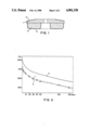
- FIG. 2 illustrates the comparison between the cooling curve of a rotary graphite composite anode coated according to the invention and the cooling curves of pyrolytically coated and uncoated rotary graphite composite electrodes.
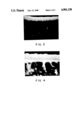
- FIG. 3 illustrates the break of a pyrolytically coated graphite part recorded by a grid electron micrograph picture at 6000-times enlargement.
- FIG. 4 illustrates the break of a graphite part coated according to the invention recorded by grid electron microscopic picture at 10,000-times enlargement.
- a rotary graphite composite anode manufactured according to the present invention comprises a basic body 1 made from a high-melting alloy such as the molybdenum alloy TZM, having a radiation path or focal track coating 2 consisting of a tungsten-rhenium alloy, and a graphite part 3, which is attached to the basic body 1 by means such as soldering, and which is provided with a plasmalytically deposited carbon coating 4 applied to its surface.
- This rotary anode has a heat capacity ofabout 700 kJ based on a maximum operating temperature of 1200° C.
- the rotary anode is coated on a conventional ion Plating-coating machine with two electron guns and an additional auxiliary anode ("triode arrangement").
- the graphite composite anode in the finished condition i.e., soldered condition
- the composite anode was subjected to vacuum annealing at 1350° C. for a duration of 5 hours, which effected substantial degassing of the graphite part of the rotary anode.
- the composite anode was then immediately installed in acoating furnace. This furnace was evacuated by pumping to a pressure of 10 Pa and simultaneously heated by radiation to a temperature of approximately 500° C.
- the graphite part of the rotary anode was degassed again in the course of this operation.
- the surface of the graphite part was atomically cleaned for half an hour under an argon atmosphere of 1 Pa and with throttled suction,by applying a d.c. voltage of 5 kV.
- the rotary anode was simultaneously heated to about 650° C.
- the coating process was started by feeding propane into the operating glow discharge, whereby the partial pressure of the propane was increased to about 50 % to 80 of the total pressure of 0.5 to 2 Pa.
- the glow discharge was maintained in the course of coating by a workpiece voltage of -1000 to -3000 volts.
- a voltage of +30 to +100 volts to the auxiliary anode By applying a voltage of +30 to +100 volts to the auxiliary anode, the degree of ionization of the plasma was increased, so that a current density of about 0.1 mA/cm 2 , was obtained on the surface of the graphite.
- the carbon coating deposited on the graphite surface of the rotary anode by the procedure of the invention had a layer thickness of 5 ⁇ m.
- the rotary graphite composite anode coated according to the invention was compared on a tube test stand with two conventional rotary graphite composite anodes having the same dimensions and material structure to testthe anodes for thermal emissivity and resistance to high voltage.
- One conventional anode had an uncoated graphite part and the other had a pyrolytically coated graphite part.
- the rotary anodes were exposed to a tube voltage of 85 kV and a tube current of 250 mA, with an electron beam gun shot duration of 6.4 seconds.
- pauses of 150 second duration were scheduled between the individual exposures of both the rotary anode of the present invention and the conventional uncoated rotary anode.
- the pause period had to be increased to 190 seconds for the pyrolytically coated rotary anode in order not to exceed the limit temperature.
- FIG. 2 illustrates the temperature-time curves recorded for of the three different rotary anodes during the operation of the tube.
- the cooling curve of the uncoated rotary anode is denoted by reference numeral 1, the cooling curve of the pyrolytically coated rotary anode by reference numeral 2, and the cooling curve of the rotary anode coated according to the invention by reference numeral 3.
- the radiation cooling of the anode coated according to the invention is substantially the same as with the uncoated graphite whereas the anode with pyrolytically coated graphite exhibits a distinctly lower cooling rate.
- the anode with pyrolytically coated graphite operates in the tubeat distinctly higher temperatures.
- the thermal emissivity was measured on the graphite anode manufactured according to the invention and with pyrolytic-coated and uncoated anodes at a radiation measuring Point.
- the coating was carried out under the sameconditions as applied in the coating of the rotary anodes.
- the rotary anodes were tested for their resistance to high voltage on the X-ray tube test stand.
- the tube voltage was increased to 180 kV. Based on the frequency of flash-overs occurring in the test, it was found that the rotary anode coated according to the invention and the one coated pyrolytically had a comparable resistance to high voltage that was significantly enhanced as compared to the uncoated rotary anode.
- FIG. 3 illustrates the lamella-like structure of a pyrolytically deposited carbon coating, which distinctly differs from the fine crystalline, break-amorphous structure of a carbon layer deposited according to the invention, as shown in FIG. 4.
Landscapes
- Chemical & Material Sciences (AREA)
- Inorganic Chemistry (AREA)
- General Chemical & Material Sciences (AREA)
- Chemical Kinetics & Catalysis (AREA)
- Engineering & Computer Science (AREA)
- Materials Engineering (AREA)
- Mechanical Engineering (AREA)
- Metallurgy (AREA)
- Organic Chemistry (AREA)
- Carbon And Carbon Compounds (AREA)
Applications Claiming Priority (2)
| Application Number | Priority Date | Filing Date | Title |
|---|---|---|---|
| AT1959/87A AT391223B (de) | 1987-08-03 | 1987-08-03 | Verfahren zur herstellung einer drehanode fuer roentgenroehren |
| AT1959/87 | 1987-08-03 |
Related Parent Applications (1)
| Application Number | Title | Priority Date | Filing Date |
|---|---|---|---|
| US07226760 Continuation | 1988-08-01 |
Publications (1)
| Publication Number | Publication Date |
|---|---|
| US4901338A true US4901338A (en) | 1990-02-13 |
Family
ID=3524750
Family Applications (1)
| Application Number | Title | Priority Date | Filing Date |
|---|---|---|---|
| US07/366,239 Expired - Lifetime US4901338A (en) | 1987-08-03 | 1989-06-12 | Rotary anode for X-ray tubes and method of manufacture |
Country Status (4)
| Country | Link |
|---|---|
| US (1) | US4901338A (fr) |
| EP (1) | EP0302552B1 (fr) |
| AT (1) | AT391223B (fr) |
| DE (1) | DE3865147D1 (fr) |
Cited By (12)
| Publication number | Priority date | Publication date | Assignee | Title |
|---|---|---|---|---|
| US5204891A (en) * | 1991-10-30 | 1993-04-20 | General Electric Company | Focal track structures for X-ray anodes and method of preparation thereof |
| US6002745A (en) * | 1998-06-04 | 1999-12-14 | Varian Medical Systems, Inc. | X-ray tube target assembly with integral heat shields |
| WO2000012447A1 (fr) * | 1998-08-31 | 2000-03-09 | Textron Systems Corporation | Procede de production de revetements bores ameliores sur du graphite, et articles ainsi obtenus |
| US6078644A (en) * | 1998-07-01 | 2000-06-20 | Varian Medical Systems, Inc. | Carbon-backed x-ray target with coating |
| US20030042836A1 (en) * | 2001-08-28 | 2003-03-06 | Shiffler Donald A. | Carbonized resin coated anode |
| US6554179B2 (en) | 2001-07-06 | 2003-04-29 | General Atomics | Reaction brazing of tungsten or molybdenum body to carbonaceous support |
| US20070064874A1 (en) * | 2005-07-25 | 2007-03-22 | Eberhard Lenz | Rotary anode x-ray radiator |
| RU2315710C2 (ru) * | 2006-03-01 | 2008-01-27 | Институт физики твердого тела РАН | Способ пиролитического уплотнения лент из графитовой фольги |
| US20090086920A1 (en) * | 2007-09-30 | 2009-04-02 | Lee David S K | X-ray Target Manufactured Using Electroforming Process |
| RU2366606C1 (ru) * | 2008-06-07 | 2009-09-10 | Закрытое акционерное общество "Институт новых углеродных материалов и технологий" (ЗАО "ИНУМиТ") | Способ непрерывного пиролитического насыщения пористого длинномерного материала и устройство для его осуществления |
| WO2018132841A1 (fr) * | 2017-01-16 | 2018-07-19 | Varex Imaging Corporation | Cible anodique à grand angle pour tube à rayons x et structure cathodique orthogonale |
| CN109243948A (zh) * | 2018-09-30 | 2019-01-18 | 汕头高新区聚德医疗科技有限公司 | 一种高稳定性ct球管 |
Families Citing this family (1)
| Publication number | Priority date | Publication date | Assignee | Title |
|---|---|---|---|---|
| FR2686732B1 (fr) * | 1992-01-24 | 1994-03-18 | General Electric Cgr | Anode en graphite pour tube a rayons x et tube ainsi obtenu. |
Citations (2)
| Publication number | Priority date | Publication date | Assignee | Title |
|---|---|---|---|---|
| US4335327A (en) * | 1978-12-04 | 1982-06-15 | The Machlett Laboratories, Incorporated | X-Ray tube target having pyrolytic amorphous carbon coating |
| US4516255A (en) * | 1982-02-18 | 1985-05-07 | Schwarzkopf Development Corporation | Rotating anode for X-ray tubes |
Family Cites Families (7)
| Publication number | Priority date | Publication date | Assignee | Title |
|---|---|---|---|---|
| DE2146918B2 (de) * | 1971-09-20 | 1978-06-01 | Siemens Ag, 1000 Berlin Und 8000 Muenchen | Roentgenroehren-drehanode |
| US4060660A (en) * | 1976-01-15 | 1977-11-29 | Rca Corporation | Deposition of transparent amorphous carbon films |
| DE2928993C2 (de) * | 1979-07-18 | 1982-12-09 | Philips Patentverwaltung Gmbh, 2000 Hamburg | Verfahren zur Herstellung einer Röntgenröhren-Drehanode |
| DE3013441C2 (de) * | 1980-04-05 | 1984-12-13 | Philips Patentverwaltung Gmbh, 2000 Hamburg | Anodenteller für eine Drehanoden-Röntgenröhre und Verfahren zu seiner Herstellung |
| GB2084124A (en) * | 1980-09-15 | 1982-04-07 | Gen Electric | Improved graphite X-ray tube target |
| US4481655A (en) * | 1982-04-01 | 1984-11-06 | General Electric Company | X-Ray target attachment |
| DE3236104A1 (de) * | 1982-09-29 | 1984-03-29 | Siemens AG, 1000 Berlin und 8000 München | Hochleistungs-roentgendrehanode und verfahren zu ihrer herstellung |
-
1987
- 1987-08-03 AT AT1959/87A patent/AT391223B/de not_active IP Right Cessation
-
1988
- 1988-07-21 DE DE8888201584T patent/DE3865147D1/de not_active Expired - Lifetime
- 1988-07-21 EP EP88201584A patent/EP0302552B1/fr not_active Expired - Lifetime
-
1989
- 1989-06-12 US US07/366,239 patent/US4901338A/en not_active Expired - Lifetime
Patent Citations (2)
| Publication number | Priority date | Publication date | Assignee | Title |
|---|---|---|---|---|
| US4335327A (en) * | 1978-12-04 | 1982-06-15 | The Machlett Laboratories, Incorporated | X-Ray tube target having pyrolytic amorphous carbon coating |
| US4516255A (en) * | 1982-02-18 | 1985-05-07 | Schwarzkopf Development Corporation | Rotating anode for X-ray tubes |
Cited By (19)
| Publication number | Priority date | Publication date | Assignee | Title |
|---|---|---|---|---|
| AT399789B (de) * | 1991-10-30 | 1995-07-25 | Gen Electric | Verfahren zum herstellen einer röntgenröhrenanode und eines graphitsubstrates hiefür |
| US5204891A (en) * | 1991-10-30 | 1993-04-20 | General Electric Company | Focal track structures for X-ray anodes and method of preparation thereof |
| US6002745A (en) * | 1998-06-04 | 1999-12-14 | Varian Medical Systems, Inc. | X-ray tube target assembly with integral heat shields |
| US6078644A (en) * | 1998-07-01 | 2000-06-20 | Varian Medical Systems, Inc. | Carbon-backed x-ray target with coating |
| GB2357779B (en) * | 1998-08-31 | 2003-08-06 | Textron Systems Corp | Process for the production of improved boron coatings onto a porous substrate and article obtained in this process |
| WO2000012447A1 (fr) * | 1998-08-31 | 2000-03-09 | Textron Systems Corporation | Procede de production de revetements bores ameliores sur du graphite, et articles ainsi obtenus |
| GB2357779A (en) * | 1998-08-31 | 2001-07-04 | Textron Systems Corp | Process for the production of improved boron coatings onto graphite and article obtained in this process |
| US6554179B2 (en) | 2001-07-06 | 2003-04-29 | General Atomics | Reaction brazing of tungsten or molybdenum body to carbonaceous support |
| US20030042836A1 (en) * | 2001-08-28 | 2003-03-06 | Shiffler Donald A. | Carbonized resin coated anode |
| US6856080B2 (en) * | 2001-08-28 | 2005-02-15 | The United States Of America As Represented By The Secretary Of The Air Force | Carbonized resin coated anode |
| US7489763B2 (en) * | 2005-07-25 | 2009-02-10 | Siemens Aktiengesellschaft | Rotary anode x-ray radiator |
| US20070064874A1 (en) * | 2005-07-25 | 2007-03-22 | Eberhard Lenz | Rotary anode x-ray radiator |
| RU2315710C2 (ru) * | 2006-03-01 | 2008-01-27 | Институт физики твердого тела РАН | Способ пиролитического уплотнения лент из графитовой фольги |
| US20090086920A1 (en) * | 2007-09-30 | 2009-04-02 | Lee David S K | X-ray Target Manufactured Using Electroforming Process |
| RU2366606C1 (ru) * | 2008-06-07 | 2009-09-10 | Закрытое акционерное общество "Институт новых углеродных материалов и технологий" (ЗАО "ИНУМиТ") | Способ непрерывного пиролитического насыщения пористого длинномерного материала и устройство для его осуществления |
| WO2018132841A1 (fr) * | 2017-01-16 | 2018-07-19 | Varex Imaging Corporation | Cible anodique à grand angle pour tube à rayons x et structure cathodique orthogonale |
| US10755887B2 (en) | 2017-01-16 | 2020-08-25 | Varex Imaging Corporation | Large angle anode target for an X-ray tube and orthogonal cathode structure |
| CN109243948A (zh) * | 2018-09-30 | 2019-01-18 | 汕头高新区聚德医疗科技有限公司 | 一种高稳定性ct球管 |
| CN109243948B (zh) * | 2018-09-30 | 2024-11-22 | 汕头高新区聚德医疗科技有限公司 | 一种高稳定性ct球管 |
Also Published As
| Publication number | Publication date |
|---|---|
| EP0302552B1 (fr) | 1991-09-25 |
| EP0302552A3 (en) | 1989-05-10 |
| EP0302552A2 (fr) | 1989-02-08 |
| ATA195987A (de) | 1990-02-15 |
| AT391223B (de) | 1990-09-10 |
| DE3865147D1 (de) | 1991-10-31 |
Similar Documents
| Publication | Publication Date | Title |
|---|---|---|
| US4901338A (en) | Rotary anode for X-ray tubes and method of manufacture | |
| Mattox et al. | Structure modification by ion bombardment during deposition | |
| US4090103A (en) | X-ray target | |
| US8036341B2 (en) | Stationary x-ray target and methods for manufacturing same | |
| US4419202A (en) | Metal coatings | |
| US20100055487A1 (en) | Method for coating a substrate surface and coated product | |
| US20100040201A1 (en) | Cathode with a Coating Near the Filament and Methods for Making Same | |
| US5227129A (en) | Method for applying corrosion resistant metallic coating of zirconium nitride | |
| Musa et al. | Pure metal vapor plasma source with controlled energy of ions | |
| US3772174A (en) | Deposition of alloy films | |
| US4600659A (en) | Emissive coating on alloy x-ray tube target | |
| JP2003321760A (ja) | プラズマ処理容器内部材およびその製造方法 | |
| US5098540A (en) | Method for depositing chromium coatings for titanium oxidation protection | |
| JP2791977B2 (ja) | X線管用回転陽極及びその製造方法 | |
| GB2090291A (en) | Sputter ion plating of refractory metal/metal compounds | |
| US5061357A (en) | Method of producing an electron beam emission cathode | |
| US4412901A (en) | Method for the manufacture of solid electrolyte layers for galvanic cells | |
| JPH09106751A5 (fr) | ||
| JPH02280310A (ja) | 電解コンデンサ用電極材料の製造方法 | |
| US20080268281A1 (en) | Shield Components With Enhanced Thermal and Mechanical Stability | |
| US12410509B2 (en) | Copper-coated aluminum wire material and production method therefor | |
| GB2574220A (en) | Thermal and electron-beam PVD deposition of metals | |
| US2175695A (en) | Gettering | |
| Bodhansky et al. | Formation of various coatings and their behaviour under particle bombardment | |
| US4089990A (en) | Battery plate and method of making |
Legal Events
| Date | Code | Title | Description |
|---|---|---|---|
| STCF | Information on status: patent grant |
Free format text: PATENTED CASE |
|
| AS | Assignment |
Owner name: SCHWARZKOPF TECHNOLOGIES CORPORATION, A CORP. OF M Free format text: CHANGE OF NAME;ASSIGNOR:SCHWARZKOPF DEVELOPMENT CORPORATION, A CORP. OF MD;REEL/FRAME:005931/0448 Effective date: 19910517 |
|
| CC | Certificate of correction | ||
| FPAY | Fee payment |
Year of fee payment: 4 |
|
| FEPP | Fee payment procedure |
Free format text: PAYOR NUMBER ASSIGNED (ORIGINAL EVENT CODE: ASPN); ENTITY STATUS OF PATENT OWNER: LARGE ENTITY |
|
| FPAY | Fee payment |
Year of fee payment: 8 |
|
| FPAY | Fee payment |
Year of fee payment: 12 |