US4901558A - Seal integrity tester and method - Google Patents
Seal integrity tester and method Download PDFInfo
- Publication number
- US4901558A US4901558A US07/288,676 US28867688A US4901558A US 4901558 A US4901558 A US 4901558A US 28867688 A US28867688 A US 28867688A US 4901558 A US4901558 A US 4901558A
- Authority
- US
- United States
- Prior art keywords
- vacuum
- container
- chamber
- test
- displacement
- Prior art date
- Legal status (The legal status is an assumption and is not a legal conclusion. Google has not performed a legal analysis and makes no representation as to the accuracy of the status listed.)
- Expired - Fee Related
Links
- 238000000034 method Methods 0.000 title claims abstract description 21
- 238000012360 testing method Methods 0.000 claims abstract description 83
- 238000006073 displacement reaction Methods 0.000 claims abstract description 27
- 229920003023 plastic Polymers 0.000 claims description 15
- 230000015556 catabolic process Effects 0.000 claims description 7
- 238000006731 degradation reaction Methods 0.000 claims description 7
- 239000000463 material Substances 0.000 claims description 7
- 238000012545 processing Methods 0.000 claims description 6
- 238000010998 test method Methods 0.000 claims description 4
- 230000001939 inductive effect Effects 0.000 claims description 2
- 238000011156 evaluation Methods 0.000 claims 1
- 238000005070 sampling Methods 0.000 claims 1
- 238000010586 diagram Methods 0.000 description 6
- QSHDDOUJBYECFT-UHFFFAOYSA-N mercury Chemical compound [Hg] QSHDDOUJBYECFT-UHFFFAOYSA-N 0.000 description 6
- 229910052753 mercury Inorganic materials 0.000 description 6
- 238000007789 sealing Methods 0.000 description 6
- 239000007789 gas Substances 0.000 description 4
- 230000001066 destructive effect Effects 0.000 description 3
- 230000005494 condensation Effects 0.000 description 2
- 238000009833 condensation Methods 0.000 description 2
- 230000001419 dependent effect Effects 0.000 description 2
- 238000013461 design Methods 0.000 description 2
- 235000013305 food Nutrition 0.000 description 2
- 230000004044 response Effects 0.000 description 2
- 229910001250 2024 aluminium alloy Inorganic materials 0.000 description 1
- 229920004943 Delrin® Polymers 0.000 description 1
- 229920000459 Nitrile rubber Polymers 0.000 description 1
- 238000005299 abrasion Methods 0.000 description 1
- NIXOWILDQLNWCW-UHFFFAOYSA-N acrylic acid group Chemical group C(C=C)(=O)O NIXOWILDQLNWCW-UHFFFAOYSA-N 0.000 description 1
- 230000015572 biosynthetic process Effects 0.000 description 1
- HGAZMNJKRQFZKS-UHFFFAOYSA-N chloroethene;ethenyl acetate Chemical compound ClC=C.CC(=O)OC=C HGAZMNJKRQFZKS-UHFFFAOYSA-N 0.000 description 1
- 238000004891 communication Methods 0.000 description 1
- 239000002131 composite material Substances 0.000 description 1
- 238000004590 computer program Methods 0.000 description 1
- 230000003750 conditioning effect Effects 0.000 description 1
- IDLFZVILOHSSID-OVLDLUHVSA-N corticotropin Chemical compound C([C@@H](C(=O)N[C@@H](CO)C(=O)N[C@@H](CCSC)C(=O)N[C@@H](CCC(O)=O)C(=O)N[C@@H](CC=1NC=NC=1)C(=O)N[C@@H](CC=1C=CC=CC=1)C(=O)N[C@@H](CCCNC(N)=N)C(=O)N[C@@H](CC=1C2=CC=CC=C2NC=1)C(=O)NCC(=O)N[C@@H](CCCCN)C(=O)N1[C@@H](CCC1)C(=O)N[C@@H](C(C)C)C(=O)NCC(=O)N[C@@H](CCCCN)C(=O)N[C@@H](CCCCN)C(=O)N[C@@H](CCCNC(N)=N)C(=O)N[C@@H](CCCNC(N)=N)C(=O)N1[C@@H](CCC1)C(=O)N[C@@H](C(C)C)C(=O)N[C@@H](CCCCN)C(=O)N[C@@H](C(C)C)C(=O)N[C@@H](CC=1C=CC(O)=CC=1)C(=O)N1[C@@H](CCC1)C(=O)N[C@@H](CC(N)=O)C(=O)NCC(=O)N[C@@H](C)C(=O)N[C@@H](CCC(O)=O)C(=O)N[C@@H](CC(O)=O)C(=O)N[C@@H](CCC(O)=O)C(=O)N[C@@H](CO)C(=O)N[C@@H](C)C(=O)N[C@@H](CCC(O)=O)C(=O)N[C@@H](C)C(=O)N[C@@H](CC=1C=CC=CC=1)C(=O)N1[C@@H](CCC1)C(=O)N[C@@H](CC(C)C)C(=O)N[C@@H](CCC(O)=O)C(=O)N[C@@H](CC=1C=CC=CC=1)C(O)=O)NC(=O)[C@@H](N)CO)C1=CC=C(O)C=C1 IDLFZVILOHSSID-OVLDLUHVSA-N 0.000 description 1
- 238000013479 data entry Methods 0.000 description 1
- 229920001971 elastomer Polymers 0.000 description 1
- 239000012530 fluid Substances 0.000 description 1
- 230000006870 function Effects 0.000 description 1
- 239000011521 glass Substances 0.000 description 1
- 238000007689 inspection Methods 0.000 description 1
- 230000013011 mating Effects 0.000 description 1
- 238000005259 measurement Methods 0.000 description 1
- 238000010606 normalization Methods 0.000 description 1
- 230000003287 optical effect Effects 0.000 description 1
- 230000002093 peripheral effect Effects 0.000 description 1
- 238000003908 quality control method Methods 0.000 description 1
- 238000007666 vacuum forming Methods 0.000 description 1
- 238000013022 venting Methods 0.000 description 1
- 238000011179 visual inspection Methods 0.000 description 1
Images

Classifications
-
- G—PHYSICS
- G01—MEASURING; TESTING
- G01M—TESTING STATIC OR DYNAMIC BALANCE OF MACHINES OR STRUCTURES; TESTING OF STRUCTURES OR APPARATUS, NOT OTHERWISE PROVIDED FOR
- G01M3/00—Investigating fluid-tightness of structures
- G01M3/02—Investigating fluid-tightness of structures by using fluid or vacuum
- G01M3/36—Investigating fluid-tightness of structures by using fluid or vacuum by detecting change in dimensions of the structure being tested
- G01M3/363—Investigating fluid-tightness of structures by using fluid or vacuum by detecting change in dimensions of the structure being tested the structure being removably mounted in a test cell
Definitions
- This invention relates generally to testing sealed containers and more specifically to a non-destructive vacuum and displacement test for seal integrity of sealed plastic containers.
- sensors are used in connection with placing the container in an evacuated chamber. The walls of the container bulge in this condition since the pressure is greater inside the container than outside the container (i.e., within the chamber). The sensors then gauge a maximum deflection value of the container wall against a predetermined threshold value. If the package deflection is greater than this value, it is considered to have passed the test. However, if the maximum package deflection is less than this value, it is considered to have failed the test, the reasoning being that the container did not bulge due to a leak.
- the present invention provides a reliable method and apparatus for testing, in a non-destructive manner, the seal integrity of a sealed container for foodstuffs, among others.
- a microprocessor simultaneously examines the measured deflection of the walls or sides of sealed packages placed in a vacuum and evaluates the status of the vacuum within the vacuum chamber. In this manner, various types of leaks, including slow leaks or leaks which quickly plug, may be accurately ascertained.
- the device also includes several other features which enhance its efficiency, utility and accuracy in determining the integrity of the seal of a plurality of sealed packages, each in their own vacuum chamber.
- the packages to be tested fit in concave trays affixed to a vacuum chamber base.
- the trays are configured and arranged to allow the containers top and bottom to expand.
- Displacement type transducers extend up through the base and trays to cooperatively contact the bottom of the packages to be tested.
- a vacuum chamber lid which is hingedly attached to the base, is then lowered over the trays, sealing each package within an individual chamber.
- a second set of displacement transducers extend through the lid to cooperatively contact the top of the sealed packages.
- an atmospheric pressure transducer and means to evacuate the chamber so as to form a vacuum therein. Therefore, within each sealed chamber there is located a tray, a package to be tested, two displacement transducers in contact with the package, an atmospheric pressure transducer, and means to evacuate the chamber.
- transducers are connected to an analog-to-digital converter which provides information to a microprocessor.
- a software program utilizes the input from the transducers to determine the integrity of the sealed packages by evaluating the input against preselected pass/fail criteria.
- messages from the microprocessor are displayed on an information output device (e.g., a printer or video display monitor).
- the microprocessor also computes longer term values for each individual chamber and the plurality of chambers (hereinafter referred to for convenience as a "nest").
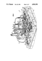
- FIG. 1 is a perspective view, with portions broken away, of a test fixture 10 of the present invention constructed according to the principles of the present invention
- FIG. 2 is a perspective view of a portion of vacuum chamber lid 12 of the test fixture 10 of FIG. 1;
- FIG. 3 is a cross-sectional view taken through line 3--3 of FIG. 2;
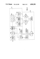
- FIG. 4 is a block diagram illustrating functional elements of a preferred embodiment measurement device constructed according to the principles of the present invention.
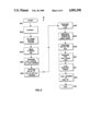
- FIG. 5 is a logic block diagram illustrating computer program operation of the device of FIG. 4;
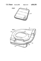
- FIG. 6 is a perspective view of a sealed package 60.
- FIG. 7 is an enlarged view of a portion of the sealed package of FIG. 6.
- this invention provides a more accurate test of the integrity of the seal of such packages by utilizing data input from deflection/displacement transducers and atmospheric pressure transducers.
- An algorithm (described below) used by a central processing unit (“microprocessor") evaluates the data provided by the transducers and provides pass/fail results of the containers.
- FIG. 1 An example of a preferred embodiment of a test fixture is illustrated in FIG. 1, while a functional block diagram of a preferred embodiment of the present invention is illustrated in FIG. 4.
- the chambers 20 are evacuated of air to approximately 26.4 inches of mercury.
- the chamber vacuum solenoid valves 41 are then closed.
- the readings for the top and bottom package deflection sensors 22, 23 and the vacuum level sensors 24 are captured at a rate of 20 times per second for three seconds.
- the microprocessor 46 then computes various maximum readings and average readings and determines if individual packages 60 (best seen in FIGS. 6 and 7) fail based on predetermined criteria.
- a nominal vacuum range of 0.88 ⁇ 29.9 inches of mercury or greater is required in the preferred embodiment to establish a differential between the established atmosphere in chamber 20 and any escaping gases from the container 60 under test in order to make such gases readily detectable.
- This vacuum range may vary for other styles of containers as will become apparent to one skilled in the art and, accordingly, the present invention should not be so limited.
- test fixture 10 To facilitate understanding of the apparatus, a further description of the functional blocks of FIG. 4 and microprocessor algorithm 51 (best seen in FIG. 5) will now be deferred pending a more complete description of test fixture 10.
- test fixture 10 which practices and implements the present invention.
- the test fixture 10 is comprised of a vacuum chamber base 11 having a smooth upper surface 38), a vacuum chamber lid 12 (a portion of which seals against surface 38), attendant components (described further below) and a support structure 16.
- vacuum chamber lid 12 is comprised of a lower section 30, having formed therein a plurality of chambers 20a-20f, and a top section 31 attached to lower section 30 via bolts 15 or other suitable fastening devices.
- Top section 31 has holes formed therein such that top transducers 22a-22f (described further below) may extend through top section 31 into chambers 20 to cooperatively engage or contact the top of the sealed package/container 60 during the test procedure.
- base 11 has holes formed therein such that bottom transducers 23a-23f may extend therethrough into chambers 20 to cooperatively engage or contact the lower surface or bottom (not shown) of the plastic containers 60.
- a concave form 21a-21f Located within each chamber 20, when vacuum chamber lid 12 is in its down/operative position, is a concave form 21a-21f into which the plastic container 60 to be tested is placed.
- These forms 21 are suitably affixed or attached to surface 38 to maintain their desired location.
- "dowel-like" protrusions extend up from base 11 into mating holes (not shown) formed into the base of the forms 21.
- the forms 21 preferably have an open top and four sides.
- the interior bottom 39 of forms 21 slopes downward from the side walls to the opening in the center for bottom transducer 23 to allow container 60 to bulge downward.
- Form 21 also preferably provides for free gaseous flow beneath the form 21, in part dependent upon the placement of the chamber evacuation means 71 and vacuum sensors 24.
- Forms 21 are arranged and configured to seat container 60 snugly around the container's 60' side edges while allowing expansion of the top 61 and bottom 64 of container 60.
- the form 21 is open at its top while the interior bottom 30 slopes downward, as noted above, to provide for the distension of the top 61 and bottom 64 of container 60.
- the form 21 itself is approximately rectangular in shape and fits within the approximately rectangular box shape of chamber 61.
- the container 60 evaluated by the preferred embodiment test fixture 10 is a container for Top Shelf style food products, sold by the assignee of the present invention.
- This container 60 also has an approximately rectangular box shape. Also illustrated in FIGS. 6 and 7 are pull tab 63 to open container 60 and container lips 62 and 65.
- the forms 21 are preferably manufactured of a material which does not "gas off” when in a vacuum so that vacuum readings are not affected.
- the forms are made of Delrin® type plastic composite material.
- vacuum transducers/sensors 24 located within/extending-through base 11 are vacuum transducers/sensors 24 (described further below) and openings suitable for evacuating and/or venting the chambers 20.
- Handle 19 is attached to lid 12 providing or the manual raising and lowering of lid 12.
- Lid 12 is hingedly attached to table surface 11 by means of hinge 14 and hinge pin 13, each of which are suitably attached to lid 12 and base 11 via bolts 15. It will be apparent to those skilled in the art that although numerous bolts 15 are illustrated in the accompanying Figures, no effort has been made to correlate each and every bolt 15 to those illustrated. Those skilled in the art will recognize that other suitable fastening devices, welds, rivets, etc., might similarly be used in such a test fixture 10 as described herein.
- connection extension members 33, 34 are also attached to base 11 .
- Members 33, 34 are used to ensure that transducer connections 25, 26 are maintained at a secure distance to avoid pinching the connections 25, 26 during the opening and closing of lid 12 during fixture 10's operation.
- Preferably means for removing the top portion of members 33 and 34 at the connection guide holes 75 are provided. This allows placing connections 25, 26 through connection guide holes 75 formed therethrough without having to disconnect the connection wires 25, 26.
- Transducer connections 32 are grouped into connection. 26 and extend through base 11 (via strain relief connector 101) to multiplexor 43.
- cylinder 18 pivotally attached to lid 12.
- the extension rod of cylinder 18 is attached to base 11 to aid and damp the raising and lowering of vacuum chamber lid 12.
- Air cylinder 18 dampens this upward motion to provide safe operation of test fixture 10.
- Air pressure adjustment means (not shown) allows adjustment of the rate of opening of lid 12.
- Cylinder 18 may also be hydraulic or other suitable style cylinder.
- an RS-232 serial interface port 37 (with its cover closed) for data entry by a device (such as a serial information input mouse, not shown) or for communicating to a host computer (not shown).
- a device such as a serial information input mouse, not shown
- a host computer not shown
- Support structure 16 of fixture 10 may be used to house other components of the apparatus such as chamber evacuation means 71 comprised of vacuum pump 42, solenoid valves 41 and expansion tank 49 (as best seen in FIG. 4).
- chamber evacuation means 71 comprised of vacuum pump 42, solenoid valves 41 and expansion tank 49 (as best seen in FIG. 4).
- solenoid valves 41 is desirable in order to locate the valves 41 as close as possible to the test chambers 20 so as to reduce the amount of air/gaseous medium required to be evacuated from the test chambers 20 during the test operation procedure.
- bottom section 30 and base 11 are made of 2024 aluminum material.
- top section 31 is preferably made of an acrylic sheet. Use of this type of transparent plastic allows for visual inspection of chambers 20 during operation of the test. Other abrasion resistant plastic materials or glass could similarly be used.
- chamber 20d of milled section 30, there is illustrated chamber 20d of milled section 30, as viewed from the side which contacts table surface 11. It will be apparent to those skilled in the art that first, although chamber 20d is illustrated, other chambers 20 of fixture 10 are similar in design, and second, that the shape of chamber 20d is illustrated by way of example of the preferred embodiment of fixture 10. Other sizes and shapes of chamber 20 might be used. In the preferred embodiment, chambers 20 were designed to provide minimal clearances about form 21, thereby reducing the amount of gaseous medium required to be evacuated from the chamber 20 during the test phase.
- chamber 20 has an approximately rectangular plan form and has an approximately rectangular box-like shape.
- the bottom of chamber 20 is open when lid 12 is open/raised.
- the bottom is comprised of flat surface 38 when lid 12 is closed (i.e., when lid 12 is in its operative position).
- Sealing gaskets 40 and 102 are used to seal the various portions of chambers 20.
- Sealing gasket 40d lies adjacent to and below a shoulder 100 of bottom section 30. This shoulder 41 is located about the entire periphery/perimeter of the bottom edge of each chamber 20. This gasket 40d provides a seal between shoulder 100 and base 11, more specifically flat surface 38, when vacuum chamber lid 12 is lowered.
- the choice of sealing gasket 40d as the sealing means is dependent on several factors, including in part on the evacuated atmospheric pressure of the chambers 20, the "downward" force applied to vacuum chamber lid 12 when closed to seal against flat surface 38, and the arrangement of shoulder 100, as those skilled in the art will recognize. In the preferred embodiment "O" rings manufactured by Apple Rubber Products, Inc.
- a similar O-ring 102 is used to seal bottom section 30 to top section 31 about each chamber 20 (best seen in FIG. 1).
- FIG. 4 there is illustrated a block diagram of the functional elements of a preferred embodiment of the present invention.
- the test fixture 10 with solenoid valves 41 is located between test chambers 20 and expansion tank 49. Expansion tank 49 is connected to pump 42.
- the transducers 22, 23 and sensors 24 are attached to test chambers 20 with their output fed to multiplexor cards 43 and 44.
- the multiplexor cards 43, 44 multiplex the signals from the transducers 22, 23 and sensors 24 to A to D convertor 45. This signal is then transmitted to the microprocessor 46.
- Attached to the microprocessor 46 is data input device 47 which may comprise a serial input device such as a mouse, a keyboard, or magnetic storage media among others.
- Data output device 48 may be a printer, video display unit, magnetic storage medium or other output device.
- Data processing means 70 also includes relays 65.
- program logic is resident in EPROM (not shown), it might be down loadable from ROM, serially input, loaded from magnetic medium, or resident in some other memory device.
- the various functional elements are to be properly connected to appropriate bias and reference supplies so as to operate in their intended manner.
- appropriate memory, buffer and other attendant peripheral devices are to be properly connected to microprocessor 46, A/D converter 45 relays 65, lid switch 66 and multiplexor cards 43, 44 so as to operate in their intended manner.
- interconnections between functional blocks 42, 49, 41 and 20 represent gaseous flow while the remaining interconnections represent signal paths.
- vacuum pump 42 is a single stage rotary vane vacuum style pump designated by the model number RA0063, manufactured by Bush Inc., of Downers Grove, Ill.
- the pump 42 generates three horsepower at 1,710 r.p.m. while operating at 460 volts (3-phase) and moving 41 cfm.
- any pump capable of evacuating test chambers 20 to appropriate test pressures may be utilized.
- the testing is performed at 26.4 inches of mercury.
- Other means to evacuate chambers 20 to this percentage of atmosphere may be suitable such as a vortex blower (e.g. ring compressor) and similar vacuum forming devices.
- the vacuum pump 42 is connected to the expansion tank 49 by means of conduit to provide for a gas flow path. Expansion tank 49 is kept at 29.7 inches of mercury and is maintained at that level by vacuum pump 42, which runs continuously when the apparatus is turned on, in order to aid the evacuation of test chambers 20 through solenoid valves 41.
- the solenoid valves 41 are connected to tank 49 via plastic type TYGON® tubing having a 3/4 inch interior diameter. This type of tubing provides a clear kink-resistant path. Other style tubing or pipe which is capable of withstanding the atmospheric pressures utilized in the apparatus and which resists kinking may be used.
- the connections between solenoid valves 41a-41f and chamber 20a-20f each comprise a separate tube.
- the solenoid valves 41 are 1/2 inch NPT 2-way solenoid valves manufactured by Asco Corporation, designated by the number 8030 A17VM.
- the solenoid valves are controlled by microprocessor 46 via 24 volt opto-relays 65, and are activated (i.e., closed) when the corresponding test chamber 20 reaches 26.4 inches of mercury.
- Other ranges of atmosphere may be used as those skilled in the art will recognize. The useful range depends upon the transducers and sensors used, as well as the point at which the test becomes destructive to container 60.
- the test range must provide statistically significant pass/fail rates for the containers 60 to be tested. As those skilled in the art will recognize, if one assumes that containers 60 fall into a normal distribution for seal integrity, then one can establish a percentage of quality inspection with a certain degree of confidence/accuracy. To a large extent, the criteria to pass/fail each container, to provide statistically significant pass/fail rates, must be adjusted based on physical characteristics of the container and condensation present on the container or within the chamber, among other factors.
- Transducers 22, 23 residing within chambers 20 are Novotechnick inductive position transducers.
- the transducers utilize contact sensing.
- Such contact type transducers have advantages over non-contact transducers (i.e., optical transducers) in that if the container 60 utilizes a wavy top plastic or condensation forms on the container distorted, readings may occur.
- Such other styles may be used, however.
- the sensors 22, 23 utilized in the preferred embodiment have a resolution of plus or minus 0.003 inches. This type of transducer 22, 23 is commonly called a linear transducer or LVDT.
- Microprocessor 46 To provide a reference point for transducers 22, 23, an initial reading is established prior to the formation of the vacuum in chamber 20. Microprocessor 46 also verifies that this reading is above a preset level.
- Vacuum sensors 24 are preferably model 204 vacuum transducers manufactured by Setra Systems, Inc., of Acton, Mass., designated as model number 204. These sensors have an accuracy of 0.11% of full scale. Therefore, these sensors 24, preferably mounted in base 11, are sensitive to leaks on the order of 3 microns in the container 60 to be tested. Sensors 24 provide fast response, accuracy, ruggedness and minimal signal conditioning. Sensors 24 also provide a linear output.
- the position transducers 22, 23 and sensors 24 are multiplexed through two cards.
- the first is an EXP-16 analog input expansion sub-multiplexor manufactured by MetraByte and the second is an EXP-16 with PG-408 option for the Novotechnick LVDT's.
- the output from the two multiplexors 43, 44 is transmitted to an analog-to-digital converter card 45 which provides digital information to microprocessor 46.
- the successive-approximation type analog-to-digital converter card is a DAS-8 and is manufactured by MetraByte Corp. of Taunton, Mass., designated by the number 45.
- the microprocessor 46 in the preferred embodiment is an Ampro Little Board PC model 4b-3, manufactured by Ampro Computer, Inc., of Sunnyvale, Calif., although those skilled in the art will recognize that other microprocessor devices or commonly-available personal computers may be used.
- lid microswitch 66 which senses when vacuum chamber lid 12 is in contact with base 11. This microswitch transmits a signal to microprocessor 46. Microswitch 66 is used to prevent attempting to evacuate chamber 20 prior to the chamber 20 being appropriately sealed.
- microprocessor 46 activates two other 24 volt opto-relays 65 connected to additional solenoid valves (not shown) connected to a common manifold (not shown) located between tank 49 and valves 41. One valve vents the manifold to ambient atmosphere. The second valve isolates the tank 49 from the manifold. When the manifold is vented and valves 41 are opened, the chambers 20 are vented as well and the vacuum is "released.” These two additional valves are similar to valves 41, except that they are preferably 11/2" in diameter.
- the logic flow diagram of an embodiment of program logic is shown generally at 51.
- the logic flow diagram 51 illustrates the steps taken to analyze the information provided by transducers 22, 23 and sensors 24.
- microprocessor 46 will be characterized as "proceeding" from logical block to logical block, while describing the operation of the program logic, those skilled in the art will appreciate that programming steps are being acted on by microprocessor 49.
- microprocessor 49 starts at block 501.
- Microprocessor 49 then proceeds to block 502 to initialize registers and memory, and load the programming logic 51 from EPROM (not shown). Such operation is well known to those skilled in the art and so will not be described further herein.
- valves 41 are opened putting chambers 20 in fluid communication with tank 41.
- Microprocessor 46 then waits for the test vacuum to be reached. Valves 41 are closed upon the chambers 20 being evacuated to the appropriate vacuum.
- the test is started.
- the readings for the top 22 and bottom 23 package deflection sensors and the vacuum level sensors 24 are captured at the rate of 20 times per second for three seconds, via multiplexor cards 43, 44 and A-D converter 45. These values are stored in RAM (not shown).
- the microprocessor then continues to block 507, where an average of the vacuum level loss or degradation for the first five readings and the last five readings are computed.
- a moving average of the vacuum loss for each chamber 20 is determined by computing the average loss for the six chambers 20 combined, while ignoring vacuum level readings for those tests in which 60 a package fails for any reason.
- Microprocessor 46 determines, at block 508, whether any individual chamber 20 of that test nest has failed the following six test criteria:
- top 22 and bottom 23 sensor values reaches a maximum in the first two seconds of the test interval and the normalized vacuum loss, is greater than a cutoff level 0.10% (greater than 0.30% of criteria number 3 above). This criteria is less restrictive than earlier and is a combination test. The criteria determines the top 22 and bottom 23 displacement sensor maximums in a first portion of the test interval and determines whether statistically significant vacuum degradation has occurred.
- a container 60 which fails one criteria may fail several.
- the foregoing criteria may also be adjusted for greater quality control and/or confidence as noted above.
- a one-line message is printed which indicates the test, the nest chamber 20, which criteria resulted in the failure, time of maximum deflection, the difference of the first and last five values, the normalized vacuum and the maximum sum. It will be apparent that these criteria may be modified to reflect the container 60 being tested and the desired control.
- an exponentially-smooth moving average for vacuum loss in each chamber 20 is maintained and computed.
- the moving average equals 0.90 times the moving average from the last test plus 0.10 times the vacuum loss of this test.
- the moving average is not updated for a nest if the chamber 20 failed.
- Normalized vacuum loss (actual vacuum loss)-(nest average)-((moving average for the chamber 20) (moving average for the nest)).
- pass/fail results are displayed on the video output unit and the sensor readings are stored or discarded as provided above.
- the foregoing averages, normalization, and results may be calculated and maintained for individual chambers 20 as well as for each test nest.
- the lid is raised automatically at block 512 as the chambers 20 are vented to atmospheric pressure.
- the test sequence ends.
- the operator may remove the packages 60 from the fixture 10 and record lot number, type of failure, etc. via the input device in response to preprogrammed prompts for those packages that failed. Via software prompts, the operator can then reset the program logic 51 to return to block 503 to begin a new test sequence.
- microprocessor 44 may preferably return to block 503 automatically.
Landscapes
- Physics & Mathematics (AREA)
- General Physics & Mathematics (AREA)
- Examining Or Testing Airtightness (AREA)
Priority Applications (2)
| Application Number | Priority Date | Filing Date | Title |
|---|---|---|---|
| US07/288,676 US4901558A (en) | 1988-12-22 | 1988-12-22 | Seal integrity tester and method |
| CA000607521A CA1322415C (fr) | 1988-12-22 | 1989-08-03 | Appareil de controle d'etancheite et methode correspondante |
Applications Claiming Priority (1)
| Application Number | Priority Date | Filing Date | Title |
|---|---|---|---|
| US07/288,676 US4901558A (en) | 1988-12-22 | 1988-12-22 | Seal integrity tester and method |
Publications (1)
| Publication Number | Publication Date |
|---|---|
| US4901558A true US4901558A (en) | 1990-02-20 |
Family
ID=23108153
Family Applications (1)
| Application Number | Title | Priority Date | Filing Date |
|---|---|---|---|
| US07/288,676 Expired - Fee Related US4901558A (en) | 1988-12-22 | 1988-12-22 | Seal integrity tester and method |
Country Status (2)
| Country | Link |
|---|---|
| US (1) | US4901558A (fr) |
| CA (1) | CA1322415C (fr) |
Cited By (24)
| Publication number | Priority date | Publication date | Assignee | Title |
|---|---|---|---|---|
| DE4017693A1 (de) * | 1990-06-01 | 1991-12-12 | Martin Lehmann | Verfahren und anordnung zur leckagepruefung |
| US5105654A (en) * | 1988-08-22 | 1992-04-21 | Taiyo Fishery Co., Ltd. | Method for inspecting leakage of sealed container |
| US5111684A (en) * | 1990-11-21 | 1992-05-12 | Pack Systems | Method and apparatus for leak testing packages |
| US5226316A (en) * | 1992-03-20 | 1993-07-13 | Oscar Mayer Foods Corporation | Package leak detection |
| US5230239A (en) * | 1992-02-04 | 1993-07-27 | Aliseo Gentile | Package testing apparatus and method |
| US5345829A (en) * | 1990-04-23 | 1994-09-13 | Tanken Seiko Kabushiki Kaisha | Method for predicting abnormality of mechanical seal and apparatus for predicting same |
| US5365774A (en) * | 1992-09-10 | 1994-11-22 | Gasti Verpackungsmaschinen Gmbh | Method of and apparatus for testing the seal of filled containers |
| US5513516A (en) * | 1992-05-01 | 1996-05-07 | Visi-Pack, Inc. | Method and apparatus for leak testing a container |
| US5533385A (en) * | 1995-02-06 | 1996-07-09 | Frievalt; William | Package seal integrity testing device and method of operation thereof |
| DE19542651C1 (de) * | 1995-11-15 | 1997-01-09 | Bosch Gmbh Robert | Vorrichtung zur Überprüfung der Dichtigkeit von Schlauchbeutelpackungen |
| US6167751B1 (en) * | 1997-11-26 | 2001-01-02 | Thermedics Detection, Inc. | Leak analysis |
| US6345527B1 (en) * | 1997-05-07 | 2002-02-12 | Martin Lehmann | Container tightness tester |
| WO2004083800A1 (fr) * | 2003-03-17 | 2004-09-30 | Johnson & Johnson Vision Care, Inc. | Detecteur de fuites en ligne |
| US20050283332A1 (en) * | 2003-07-02 | 2005-12-22 | Charles Webb | Method and device for inspecting and monitoring the seal integrity of sterile packages |
| US7036287B1 (en) * | 2002-07-02 | 2006-05-02 | Van Der Stahl Scientific, Inc. | Method and device for inspecting and monitoring the seal integrity of sterile packages |
| GB2433787A (en) * | 2005-11-30 | 2007-07-04 | John Rooney | Leak detecting apparatus |
| US20100077841A1 (en) * | 2008-09-30 | 2010-04-01 | BONFIGLIOLI ENGINEERING S.r.l | Method and machine for checking the condition of containers |
| US20110056275A1 (en) * | 2009-09-08 | 2011-03-10 | Industrial Dynamics Company, Ltd. | Container inspection utilizing linear force actuator |
| WO2012002792A3 (fr) * | 2010-06-28 | 2012-04-12 | Automated Data Systems S.A. De C.V. | Procédé permettant de tester le scellage hermétique d'emballages |
| US10421565B2 (en) | 2015-05-25 | 2019-09-24 | 2266170 Ontario Inc. | Apparatus and method for the detection of leaks in a sealed capsule |
| US10914652B2 (en) * | 2018-05-31 | 2021-02-09 | Wcr, Inc. | Leak detection for heat exchanger plate |
| US11035749B2 (en) * | 2019-02-07 | 2021-06-15 | Georg Fischer, LLC | Leak test system and method for thermoplastic piping |
| US11192723B2 (en) | 2017-12-13 | 2021-12-07 | Laitram, L.L.C. | Hygienic hollow frame assembly |
| US11549858B2 (en) * | 2020-08-18 | 2023-01-10 | Hyundai Motor Company | Apparatus for testing airtightness of separator for fuel cell |
Citations (23)
| Publication number | Priority date | Publication date | Assignee | Title |
|---|---|---|---|---|
| US1962556A (en) * | 1933-06-28 | 1934-06-12 | Jr Joseph R Eberhardt | Tray |
| US2790547A (en) * | 1954-10-13 | 1957-04-30 | Sutton Dorothy Jean | Laboratory tray for medical technicians |
| US3371781A (en) * | 1965-04-12 | 1968-03-05 | Owens Illinois Inc | Apparatus for inspecting sealed containers |
| US3667281A (en) * | 1970-11-04 | 1972-06-06 | Charles F Pfeifer | Vacuum tester for packages with flexible covers |
| US3804233A (en) * | 1972-10-26 | 1974-04-16 | D Gregg | Miscellaneous article holding and storing tray with detachable hold-down anchoring means |
| US3837215A (en) * | 1973-05-21 | 1974-09-24 | T Massage | Method and apparatus for testing sealed containers |
| US3840171A (en) * | 1971-11-26 | 1974-10-08 | Slater Paper Box Inc | Article carrier |
| US3991622A (en) * | 1973-11-05 | 1976-11-16 | Hisanao Aihara | Apparatus for measuring airtightness of sealed body |
| US4024956A (en) * | 1975-11-20 | 1977-05-24 | American Brands, Inc. | Method and apparatus for detecting leaks |
| US4053099A (en) * | 1976-10-04 | 1977-10-11 | The Mead Corporation | Article tray |
| US4173286A (en) * | 1978-06-26 | 1979-11-06 | Stanko John J | Reusable resilient packaging |
| US4326408A (en) * | 1979-02-09 | 1982-04-27 | Chiyuki Kanoh | Airtightness testing apparatus for watches |
| US4469271A (en) * | 1982-09-30 | 1984-09-04 | Federal Paper Board Co., Inc. | Multi-pocket tray |
| SU1120200A1 (ru) * | 1983-07-11 | 1984-10-23 | Предприятие П/Я Г-4149 | Способ контрол герметичности изделий с упругой оболочкой |
| US4645079A (en) * | 1984-10-09 | 1987-02-24 | Coulter Electronics,Inc. | Shipping and storing support |
| US4663964A (en) * | 1985-12-20 | 1987-05-12 | Warner-Lambert Company | Electronic airtightness tester |
| SU1328701A1 (ru) * | 1984-06-25 | 1987-08-07 | Предприятие П/Я Р-6668 | Способ контрол герметичности заполненных пробным газом замкнутых изделий с упругими стенками |
| US4706494A (en) * | 1986-04-25 | 1987-11-17 | Fmc Corporation | Seal integrity testing |
| US4709578A (en) * | 1984-10-30 | 1987-12-01 | Nippon Sanso Kabushiki Kaisha | Method and apparatus for determinating a vacuum degree within a flexible vacuum package |
| US4715215A (en) * | 1985-04-25 | 1987-12-29 | The Aro Corporation | Method and apparatus for testing the fluid-tight sealed integrity of a hermetically-sealed package in a rapidly-stabilized environment |
| US4722440A (en) * | 1987-03-23 | 1988-02-02 | Chrysler Motors Corporation | Tray for transporting internal combustion engine pistons |
| US4747299A (en) * | 1987-10-28 | 1988-05-31 | The Aro Corporation | Method of testing a package seal |
| US4771630A (en) * | 1985-12-20 | 1988-09-20 | Warner-Lambert Company | Method and apparatus for testing hermetic seal integrity of sealed packages and containers |
-
1988
- 1988-12-22 US US07/288,676 patent/US4901558A/en not_active Expired - Fee Related
-
1989
- 1989-08-03 CA CA000607521A patent/CA1322415C/fr not_active Expired - Fee Related
Patent Citations (23)
| Publication number | Priority date | Publication date | Assignee | Title |
|---|---|---|---|---|
| US1962556A (en) * | 1933-06-28 | 1934-06-12 | Jr Joseph R Eberhardt | Tray |
| US2790547A (en) * | 1954-10-13 | 1957-04-30 | Sutton Dorothy Jean | Laboratory tray for medical technicians |
| US3371781A (en) * | 1965-04-12 | 1968-03-05 | Owens Illinois Inc | Apparatus for inspecting sealed containers |
| US3667281A (en) * | 1970-11-04 | 1972-06-06 | Charles F Pfeifer | Vacuum tester for packages with flexible covers |
| US3840171A (en) * | 1971-11-26 | 1974-10-08 | Slater Paper Box Inc | Article carrier |
| US3804233A (en) * | 1972-10-26 | 1974-04-16 | D Gregg | Miscellaneous article holding and storing tray with detachable hold-down anchoring means |
| US3837215A (en) * | 1973-05-21 | 1974-09-24 | T Massage | Method and apparatus for testing sealed containers |
| US3991622A (en) * | 1973-11-05 | 1976-11-16 | Hisanao Aihara | Apparatus for measuring airtightness of sealed body |
| US4024956A (en) * | 1975-11-20 | 1977-05-24 | American Brands, Inc. | Method and apparatus for detecting leaks |
| US4053099A (en) * | 1976-10-04 | 1977-10-11 | The Mead Corporation | Article tray |
| US4173286A (en) * | 1978-06-26 | 1979-11-06 | Stanko John J | Reusable resilient packaging |
| US4326408A (en) * | 1979-02-09 | 1982-04-27 | Chiyuki Kanoh | Airtightness testing apparatus for watches |
| US4469271A (en) * | 1982-09-30 | 1984-09-04 | Federal Paper Board Co., Inc. | Multi-pocket tray |
| SU1120200A1 (ru) * | 1983-07-11 | 1984-10-23 | Предприятие П/Я Г-4149 | Способ контрол герметичности изделий с упругой оболочкой |
| SU1328701A1 (ru) * | 1984-06-25 | 1987-08-07 | Предприятие П/Я Р-6668 | Способ контрол герметичности заполненных пробным газом замкнутых изделий с упругими стенками |
| US4645079A (en) * | 1984-10-09 | 1987-02-24 | Coulter Electronics,Inc. | Shipping and storing support |
| US4709578A (en) * | 1984-10-30 | 1987-12-01 | Nippon Sanso Kabushiki Kaisha | Method and apparatus for determinating a vacuum degree within a flexible vacuum package |
| US4715215A (en) * | 1985-04-25 | 1987-12-29 | The Aro Corporation | Method and apparatus for testing the fluid-tight sealed integrity of a hermetically-sealed package in a rapidly-stabilized environment |
| US4663964A (en) * | 1985-12-20 | 1987-05-12 | Warner-Lambert Company | Electronic airtightness tester |
| US4771630A (en) * | 1985-12-20 | 1988-09-20 | Warner-Lambert Company | Method and apparatus for testing hermetic seal integrity of sealed packages and containers |
| US4706494A (en) * | 1986-04-25 | 1987-11-17 | Fmc Corporation | Seal integrity testing |
| US4722440A (en) * | 1987-03-23 | 1988-02-02 | Chrysler Motors Corporation | Tray for transporting internal combustion engine pistons |
| US4747299A (en) * | 1987-10-28 | 1988-05-31 | The Aro Corporation | Method of testing a package seal |
Cited By (34)
| Publication number | Priority date | Publication date | Assignee | Title |
|---|---|---|---|---|
| US5105654A (en) * | 1988-08-22 | 1992-04-21 | Taiyo Fishery Co., Ltd. | Method for inspecting leakage of sealed container |
| US5345829A (en) * | 1990-04-23 | 1994-09-13 | Tanken Seiko Kabushiki Kaisha | Method for predicting abnormality of mechanical seal and apparatus for predicting same |
| EP0459335B1 (fr) * | 1990-06-01 | 1996-09-18 | Martin Lehmann | Utilisation d'un procédé et dispositif pour l'examen de fuite |
| DE4017693A1 (de) * | 1990-06-01 | 1991-12-12 | Martin Lehmann | Verfahren und anordnung zur leckagepruefung |
| US5111684A (en) * | 1990-11-21 | 1992-05-12 | Pack Systems | Method and apparatus for leak testing packages |
| US5230239A (en) * | 1992-02-04 | 1993-07-27 | Aliseo Gentile | Package testing apparatus and method |
| US5226316A (en) * | 1992-03-20 | 1993-07-13 | Oscar Mayer Foods Corporation | Package leak detection |
| US5513516A (en) * | 1992-05-01 | 1996-05-07 | Visi-Pack, Inc. | Method and apparatus for leak testing a container |
| US5365774A (en) * | 1992-09-10 | 1994-11-22 | Gasti Verpackungsmaschinen Gmbh | Method of and apparatus for testing the seal of filled containers |
| US5533385A (en) * | 1995-02-06 | 1996-07-09 | Frievalt; William | Package seal integrity testing device and method of operation thereof |
| DE19542651C1 (de) * | 1995-11-15 | 1997-01-09 | Bosch Gmbh Robert | Vorrichtung zur Überprüfung der Dichtigkeit von Schlauchbeutelpackungen |
| US6345527B1 (en) * | 1997-05-07 | 2002-02-12 | Martin Lehmann | Container tightness tester |
| US6446493B1 (en) | 1997-05-07 | 2002-09-10 | Martin Lehmann | Container tightness tester |
| US6167751B1 (en) * | 1997-11-26 | 2001-01-02 | Thermedics Detection, Inc. | Leak analysis |
| US7036287B1 (en) * | 2002-07-02 | 2006-05-02 | Van Der Stahl Scientific, Inc. | Method and device for inspecting and monitoring the seal integrity of sterile packages |
| WO2004083800A1 (fr) * | 2003-03-17 | 2004-09-30 | Johnson & Johnson Vision Care, Inc. | Detecteur de fuites en ligne |
| US20050109086A1 (en) * | 2003-03-17 | 2005-05-26 | Duncan David F. | In-line leak detector |
| US20050283332A1 (en) * | 2003-07-02 | 2005-12-22 | Charles Webb | Method and device for inspecting and monitoring the seal integrity of sterile packages |
| US7272916B2 (en) | 2003-07-02 | 2007-09-25 | Van Der Stahl Scientific, Inc. | Method and device for inspecting and monitoring the seal integrity of sterile packages |
| EP1813928A3 (fr) * | 2005-11-30 | 2008-05-21 | John Rooney | Appareil de détection de fuite |
| GB2433787B (en) * | 2005-11-30 | 2008-12-03 | John Rooney | Flexible sealed packaging leak detector |
| GB2433787A (en) * | 2005-11-30 | 2007-07-04 | John Rooney | Leak detecting apparatus |
| US8327690B2 (en) * | 2008-09-30 | 2012-12-11 | Bonfiglioli Engineering S.R.L. | Method and machine for checking the condition of containers |
| US20100077841A1 (en) * | 2008-09-30 | 2010-04-01 | BONFIGLIOLI ENGINEERING S.r.l | Method and machine for checking the condition of containers |
| US8578760B2 (en) | 2009-09-08 | 2013-11-12 | Industrial Dynamics Company, Ltd | Container inspection utilizing linear force actuator |
| US20110056275A1 (en) * | 2009-09-08 | 2011-03-10 | Industrial Dynamics Company, Ltd. | Container inspection utilizing linear force actuator |
| WO2012002792A3 (fr) * | 2010-06-28 | 2012-04-12 | Automated Data Systems S.A. De C.V. | Procédé permettant de tester le scellage hermétique d'emballages |
| US10421565B2 (en) | 2015-05-25 | 2019-09-24 | 2266170 Ontario Inc. | Apparatus and method for the detection of leaks in a sealed capsule |
| US11192723B2 (en) | 2017-12-13 | 2021-12-07 | Laitram, L.L.C. | Hygienic hollow frame assembly |
| US11827454B2 (en) | 2017-12-13 | 2023-11-28 | Laitram, L.L.C. | Hygienic hollow frame assembly |
| US12157636B2 (en) | 2017-12-13 | 2024-12-03 | Laitram, L.L.C. | Hygienic hollow frame assembly |
| US10914652B2 (en) * | 2018-05-31 | 2021-02-09 | Wcr, Inc. | Leak detection for heat exchanger plate |
| US11035749B2 (en) * | 2019-02-07 | 2021-06-15 | Georg Fischer, LLC | Leak test system and method for thermoplastic piping |
| US11549858B2 (en) * | 2020-08-18 | 2023-01-10 | Hyundai Motor Company | Apparatus for testing airtightness of separator for fuel cell |
Also Published As
| Publication number | Publication date |
|---|---|
| CA1322415C (fr) | 1993-09-21 |
Similar Documents
| Publication | Publication Date | Title |
|---|---|---|
| US4901558A (en) | Seal integrity tester and method | |
| US5400646A (en) | Fluid containment monitoring system | |
| US5373729A (en) | Leak-detection installation for testing the gastightness of sealed packages | |
| US5029463A (en) | Leak detection device for in-line measurement of package integrity | |
| US6330823B1 (en) | Process and apparatus for testing containers | |
| EP0561645B1 (fr) | Détection de fuites d'un emballage | |
| JP4410854B2 (ja) | 包装材のシール性の検査 | |
| US5111684A (en) | Method and apparatus for leak testing packages | |
| US5513516A (en) | Method and apparatus for leak testing a container | |
| US5150605A (en) | Package integrity detection method | |
| EP2502043B1 (fr) | État de vide au repos pour procédé et système d'essai d'étanchéité par une mesure de la diminution du vide | |
| US5287729A (en) | Method of and apparatus for a leakage testing | |
| US4706494A (en) | Seal integrity testing | |
| US4663964A (en) | Electronic airtightness tester | |
| JP2583880B2 (ja) | パックの気密性検査方法及び装置 | |
| EP0741288A1 (fr) | Procédé et appareil d'essai de fuite d'au moins un pacquet flexible | |
| HK1006875B (en) | Use of a method and device for testing leakage | |
| EP0513931B1 (fr) | Procédé et dispositif de contrôle de l'étanchéité d'une emballage flexible, fermée et remplie | |
| US4951496A (en) | Method of, and apparatus for, leak testing a package | |
| CA1333530C (fr) | Methode et appareil de detection des fuites dans les emballages sous vide | |
| US20030046907A1 (en) | Packaging apparatus | |
| WO2012007190A1 (fr) | Appareil de détection de fuite et système de mise sous vide associé | |
| US10845266B2 (en) | Quick leak detection on dimensionally stable/slack packaging without the addition of test gas | |
| US4478070A (en) | Vacuum package tester and method | |
| EP1469296A1 (fr) | Procédé et dispositif d'essai de scellement ou d'étanchéité d'un emballage fabriqué à partir d'un matériau flexible ou semi-rigide |
Legal Events
| Date | Code | Title | Description |
|---|---|---|---|
| AS | Assignment |
Owner name: GEO. A. HORMEL & CO., MINNESOTA Free format text: ASSIGNMENT OF ASSIGNORS INTEREST.;ASSIGNORS:LEINING, LYNDON R.;VANDENBERG, ERIC S.;ERLANDSON, RALPH O.;REEL/FRAME:005041/0810 Effective date: 19890208 |
|
| CC | Certificate of correction | ||
| FPAY | Fee payment |
Year of fee payment: 4 |
|
| AS | Assignment |
Owner name: HORMEL FOODS CORPORATION Free format text: CHANGE OF NAME;ASSIGNOR:GEO. A. HORMEL & COMPANY;REEL/FRAME:007403/0458 Effective date: 19950329 |
|
| REMI | Maintenance fee reminder mailed | ||
| LAPS | Lapse for failure to pay maintenance fees | ||
| STCH | Information on status: patent discontinuation |
Free format text: PATENT EXPIRED DUE TO NONPAYMENT OF MAINTENANCE FEES UNDER 37 CFR 1.362 |