US4901648A - Trolley braking method and apparatus for use with conveyors - Google Patents
Trolley braking method and apparatus for use with conveyors Download PDFInfo
- Publication number
- US4901648A US4901648A US07/182,472 US18247288A US4901648A US 4901648 A US4901648 A US 4901648A US 18247288 A US18247288 A US 18247288A US 4901648 A US4901648 A US 4901648A
- Authority
- US
- United States
- Prior art keywords
- trolley
- guide wheel
- track
- speed
- braking
- Prior art date
- Legal status (The legal status is an assumption and is not a legal conclusion. Google has not performed a legal analysis and makes no representation as to the accuracy of the status listed.)
- Expired - Fee Related
Links
- 238000000034 method Methods 0.000 title claims 7
- 230000000979 retarding effect Effects 0.000 claims abstract 5
- 230000003213 activating effect Effects 0.000 claims 3
- 238000012806 monitoring device Methods 0.000 claims 2
- 238000012544 monitoring process Methods 0.000 claims 2
- 238000003825 pressing Methods 0.000 claims 2
- 238000001514 detection method Methods 0.000 claims 1
- 238000004904 shortening Methods 0.000 claims 1
- 239000012530 fluid Substances 0.000 abstract 1
- 230000001960 triggered effect Effects 0.000 description 4
- 239000000969 carrier Substances 0.000 description 3
- 230000007423 decrease Effects 0.000 description 3
- 230000006835 compression Effects 0.000 description 2
- 238000007906 compression Methods 0.000 description 2
- 230000007257 malfunction Effects 0.000 description 2
- 238000004519 manufacturing process Methods 0.000 description 2
- 239000000463 material Substances 0.000 description 2
- 230000009286 beneficial effect Effects 0.000 description 1
- 238000006073 displacement reaction Methods 0.000 description 1
- 238000009434 installation Methods 0.000 description 1
- 230000013011 mating Effects 0.000 description 1
- 230000037361 pathway Effects 0.000 description 1
- 230000000284 resting effect Effects 0.000 description 1
Images

Classifications
-
- B—PERFORMING OPERATIONS; TRANSPORTING
- B62—LAND VEHICLES FOR TRAVELLING OTHERWISE THAN ON RAILS
- B62D—MOTOR VEHICLES; TRAILERS
- B62D65/00—Designing, manufacturing, e.g. assembling, facilitating disassembly, or structurally modifying motor vehicles or trailers, not otherwise provided for
- B62D65/02—Joining sub-units or components to, or positioning sub-units or components with respect to, body shell or other sub-units or components
- B62D65/18—Transportation, conveyor or haulage systems specially adapted for motor vehicle or trailer assembly lines
-
- B—PERFORMING OPERATIONS; TRANSPORTING
- B60—VEHICLES IN GENERAL
- B60T—VEHICLE BRAKE CONTROL SYSTEMS OR PARTS THEREOF; BRAKE CONTROL SYSTEMS OR PARTS THEREOF, IN GENERAL; ARRANGEMENT OF BRAKING ELEMENTS ON VEHICLES IN GENERAL; PORTABLE DEVICES FOR PREVENTING UNWANTED MOVEMENT OF VEHICLES; VEHICLE MODIFICATIONS TO FACILITATE COOLING OF BRAKES
- B60T7/00—Brake-action initiating means
- B60T7/12—Brake-action initiating means for automatic initiation; for initiation not subject to will of driver or passenger
- B60T7/126—Brakes for railway vehicles coming into operation in case of exceeding a predetermined speed
-
- B—PERFORMING OPERATIONS; TRANSPORTING
- B61—RAILWAYS
- B61C—LOCOMOTIVES; MOTOR RAILCARS
- B61C13/00—Locomotives or motor railcars characterised by their application to special systems or purposes
- B61C13/04—Locomotives or motor railcars characterised by their application to special systems or purposes for elevated railways with rigid rails
-
- B—PERFORMING OPERATIONS; TRANSPORTING
- B61—RAILWAYS
- B61K—AUXILIARY EQUIPMENT SPECIALLY ADAPTED FOR RAILWAYS, NOT OTHERWISE PROVIDED FOR
- B61K7/00—Railway stops fixed to permanent way; Track brakes or retarding apparatus fixed to permanent way; Sand tracks or the like
- B61K7/02—Track brakes or retarding apparatus
- B61K7/04—Track brakes or retarding apparatus with clamping action
Definitions
- a system is set forth wherein a series of trolleys are guided along a trolley track by a power conveyor (usually a chain type).
- the power conveyor runs parallel to and, in this case, directly below the trolley track, however, it is commonly positioned above the trolley track also.
- the trolleys support a carrier upon which a large variety of loads can be placed for transport to any destination along the track.
- the system set forth in Murai is equipped with a device which will disengage the drive mechanism from the trolleys in the event that the support carrier collides with another carrier in front of it. While this safety feature is clearly very beneficial, it still leaves potential for a serious accident to occur.
- a problem that has been experienced with the Murai system is that the trolleys and the power conveyor have been known to become inadvertently disengaged allowing the trolleys to cruise along the track unbridled.
- Another problem is that a power conveyor malfunction allows the trolleys to travel at uncontrollable speeds along the track. If either of these situations occurs while the trolleys and load carrier are on level track, the situation is generally not that serious, but clearly undesirable.
- a power conveyor malfunction or trolley disengagement on a sloped track produces the potential for disaster.
- Another solution also involves a separate conveyor which is connected to the carrier.
- the separate conveyor is electrically driven at a speed slightly greater than that at which the power conveyor which engages the trolleys is driven.
- the power conveyor acts as a hold back to the force of the separate conveyor.
- the carrier will speed up to the pace of the separate conveyor but will go no faster.
- a third prior art solution involves an inertially triggered device that, in the event an over speed situation occurs, throws a stop in front of the carrier. While this system is less expensive than other prior art solutions, it stops the carrier in an extremely abrupt fashion which is not desirable. Moreover, by virtue of the principles upon which this system operates, it is very difficult to cushion the carrier deceleration.
- systems for the transportation of heavy, bulky items within a manufacturing plant should be compact, inexpensive and easily installed and include a mechanism by which loaded carriers traveling freely down sloped tracks can be gradually brought to a stop.
- the logic in an electronic processor monitors the time interval for a given trolley to travel from one sensor to another sensor in sequence. If that time interval is shorter than a preset time interval, then the system senses an overspeed condition and activates a brake which acts on a guide wheel of the trolley.
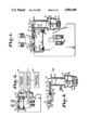
- FIG. 1 is an assembly drawing of an inverted power and free conveyor system equipped with trolley braking arrangement in accordance with the present invention.
- a load bearing carrier is shown traveling along the trolley track.
- FIG. 3 is a section view of the system shown in FIG. 1 taken along line 3--3 with the trolley's guide wheels and one support wheel visibly positioned in the free track.
- FIG. 5 is a typical braking zone cross-section in accordance with the present invention during braking operation.
- FIG. 6 is a section view of FIG. 4 taken along line 6--6 of the bottom of a typical stop cam in accordance with the present invention and the channel within which it travels.
- FIG. 1 schematically represents how the proximity switches 54 communicate with the brake 18 through a compressed air inlet 49.
- This motion causes a working cam surface 53 of the stop cam 44 to act on a mating cam surface 55 of a stop blade 50.
- the stop blade 50 is, in this example, slidably sandwiched between one flange 40 of the free track 14 and a plate 41 suitably mounted with respect to the free track 14. The sliding displacement of the stop blade 50 brings it against the trolley guide wheel 24 with clamping force, FIG. 5.
- the stop blade 50 may run the entire length of the brake zone 21 and as many spaced stop cams 44, with associated driving structure, as desired may be used.
- the resultant of the force from the spring 46 clamps the trolley guide wheel 24 between the stop blade 50 on the right and the free track flange 42 on the left, producing braking friction.
- both the free track 14 and the stop blade 50 are longitudinally stationary so that when the lateral clamping force of the stop blade 50 is applied to the trolley guide wheel 24, the wheel cannot freely roll, but rather, slides relative to either or both the free track flange 42 and the stop blade 50.
- the resulting friction applies a substantial but gradual decelerating force to the load bearing carrier through the trolley guide wheel 24 and the trolley 23.
- the present invention offers a fail-safe feature.
- a pressure sensor 65 is provided so that if the pressure drops below that which is required to keep the spring 46 compressed, an electric signal immediately stops the power conveyor 56 and sounds an alarm thereby avoiding damage to the system and alerting an attendant of a problem.
Landscapes
- Engineering & Computer Science (AREA)
- Mechanical Engineering (AREA)
- Transportation (AREA)
- Manufacturing & Machinery (AREA)
- Chemical & Material Sciences (AREA)
- Combustion & Propulsion (AREA)
- Regulating Braking Force (AREA)
- Control Of Conveyors (AREA)
Priority Applications (3)
| Application Number | Priority Date | Filing Date | Title |
|---|---|---|---|
| US07/182,472 US4901648A (en) | 1988-04-15 | 1988-04-15 | Trolley braking method and apparatus for use with conveyors |
| GB8907674A GB2219565A (en) | 1988-04-15 | 1989-04-05 | Trolley braking method and apparatus for use with conveyors |
| CA000596725A CA1308038C (fr) | 1988-04-15 | 1989-04-14 | Methode de freinage de chariot et appareil s'appliquant aux convoyeurs |
Applications Claiming Priority (1)
| Application Number | Priority Date | Filing Date | Title |
|---|---|---|---|
| US07/182,472 US4901648A (en) | 1988-04-15 | 1988-04-15 | Trolley braking method and apparatus for use with conveyors |
Publications (1)
| Publication Number | Publication Date |
|---|---|
| US4901648A true US4901648A (en) | 1990-02-20 |
Family
ID=22668633
Family Applications (1)
| Application Number | Title | Priority Date | Filing Date |
|---|---|---|---|
| US07/182,472 Expired - Fee Related US4901648A (en) | 1988-04-15 | 1988-04-15 | Trolley braking method and apparatus for use with conveyors |
Country Status (3)
| Country | Link |
|---|---|
| US (1) | US4901648A (fr) |
| CA (1) | CA1308038C (fr) |
| GB (1) | GB2219565A (fr) |
Cited By (8)
| Publication number | Priority date | Publication date | Assignee | Title |
|---|---|---|---|---|
| US5570639A (en) * | 1995-10-11 | 1996-11-05 | Fki Industries Inc. | Anti-runaway apparatus and method for a power-and-free conveyor system |
| US5606915A (en) * | 1995-04-06 | 1997-03-04 | Ford Motor Company | Power and free conveying system |
| US5636575A (en) * | 1995-11-14 | 1997-06-10 | Lico, Inc. | Conveyor speed retarder |
| US5927444A (en) * | 1997-08-15 | 1999-07-27 | Checketts; Stanley J. | Brake for a track-operated vehicle |
| CN102180185A (zh) * | 2011-04-13 | 2011-09-14 | 山东唐口煤业有限公司 | 斜巷轨道运输门式阻车机构 |
| US20170327164A1 (en) * | 2016-05-10 | 2017-11-16 | The Hi-Tech Robotic Systemz Ltd | Climb structure for a robot |
| US20180099681A1 (en) * | 2015-03-21 | 2018-04-12 | Eisenmann Se | Transport carriage and system for transporting objects |
| US10611574B2 (en) * | 2018-07-30 | 2020-04-07 | Nissan North America, Inc. | Brake assembly for conveyor system |
Citations (8)
| Publication number | Priority date | Publication date | Assignee | Title |
|---|---|---|---|---|
| US1802109A (en) * | 1930-02-11 | 1931-04-21 | Pittsburgh Plate Glass Co | Car-stopping apparatus |
| US3285195A (en) * | 1964-05-29 | 1966-11-15 | United Shoe Machinery Corp | Conveyor system control apparatus |
| US3301413A (en) * | 1964-04-10 | 1967-01-31 | Ralph W Coursey | High speed high capacity mechanical parking system |
| US3705554A (en) * | 1970-08-26 | 1972-12-12 | Standard Alliance Ind | Trolley retarder for power and free conveyors |
| US3929079A (en) * | 1971-04-30 | 1975-12-30 | Gunnar Thure Eliassen | Transport system |
| US3948187A (en) * | 1973-10-10 | 1976-04-06 | Welland Forge Limited | Power and free conveyor system |
| US4603639A (en) * | 1981-12-04 | 1986-08-05 | Si Handling Systems Inc. | Traffic control device for driverless vehicles |
| US4790247A (en) * | 1986-11-04 | 1988-12-13 | Midwest Conveyor Company, Inc. | Trolley stop for power and free conveyors |
Family Cites Families (6)
| Publication number | Priority date | Publication date | Assignee | Title |
|---|---|---|---|---|
| GB260344A (en) * | 1925-07-28 | 1926-10-28 | Union Switch & Signal Co | Improvements relating to track braking devices for railway and like vehicles |
| GB1159701A (en) * | 1966-03-16 | 1969-07-30 | Underground Mining Mach | Track Braking System. |
| CH634514A5 (de) * | 1978-11-16 | 1983-02-15 | Schweizerische Bundesbahnen | Balkengleisbremse. |
| SE455593B (sv) * | 1981-06-22 | 1988-07-25 | Carlfors Bruk E Bjorklund & Co | Vagnbroms for rangeringsendamal |
| US4596311A (en) * | 1984-09-24 | 1986-06-24 | Trailer Train Company | Brake system |
| GB2200176B (en) * | 1987-01-20 | 1991-01-02 | Becorit Limited | Vehicle and running wheel for the vehicle |
-
1988
- 1988-04-15 US US07/182,472 patent/US4901648A/en not_active Expired - Fee Related
-
1989
- 1989-04-05 GB GB8907674A patent/GB2219565A/en not_active Withdrawn
- 1989-04-14 CA CA000596725A patent/CA1308038C/fr not_active Expired - Lifetime
Patent Citations (8)
| Publication number | Priority date | Publication date | Assignee | Title |
|---|---|---|---|---|
| US1802109A (en) * | 1930-02-11 | 1931-04-21 | Pittsburgh Plate Glass Co | Car-stopping apparatus |
| US3301413A (en) * | 1964-04-10 | 1967-01-31 | Ralph W Coursey | High speed high capacity mechanical parking system |
| US3285195A (en) * | 1964-05-29 | 1966-11-15 | United Shoe Machinery Corp | Conveyor system control apparatus |
| US3705554A (en) * | 1970-08-26 | 1972-12-12 | Standard Alliance Ind | Trolley retarder for power and free conveyors |
| US3929079A (en) * | 1971-04-30 | 1975-12-30 | Gunnar Thure Eliassen | Transport system |
| US3948187A (en) * | 1973-10-10 | 1976-04-06 | Welland Forge Limited | Power and free conveyor system |
| US4603639A (en) * | 1981-12-04 | 1986-08-05 | Si Handling Systems Inc. | Traffic control device for driverless vehicles |
| US4790247A (en) * | 1986-11-04 | 1988-12-13 | Midwest Conveyor Company, Inc. | Trolley stop for power and free conveyors |
Cited By (11)
| Publication number | Priority date | Publication date | Assignee | Title |
|---|---|---|---|---|
| US5606915A (en) * | 1995-04-06 | 1997-03-04 | Ford Motor Company | Power and free conveying system |
| US5852979A (en) * | 1995-04-06 | 1998-12-29 | Ford Motor Company | Free trolley for power and free conveyors |
| US5570639A (en) * | 1995-10-11 | 1996-11-05 | Fki Industries Inc. | Anti-runaway apparatus and method for a power-and-free conveyor system |
| US5636575A (en) * | 1995-11-14 | 1997-06-10 | Lico, Inc. | Conveyor speed retarder |
| US5927444A (en) * | 1997-08-15 | 1999-07-27 | Checketts; Stanley J. | Brake for a track-operated vehicle |
| CN102180185A (zh) * | 2011-04-13 | 2011-09-14 | 山东唐口煤业有限公司 | 斜巷轨道运输门式阻车机构 |
| US20180099681A1 (en) * | 2015-03-21 | 2018-04-12 | Eisenmann Se | Transport carriage and system for transporting objects |
| US11279382B2 (en) * | 2015-03-21 | 2022-03-22 | Pentanova Cs Gmbh | Transport carriage and system for transporting objects |
| US20170327164A1 (en) * | 2016-05-10 | 2017-11-16 | The Hi-Tech Robotic Systemz Ltd | Climb structure for a robot |
| US10526030B2 (en) * | 2016-05-10 | 2020-01-07 | The Hi-Tech Robotic Systemz Ltd. | Climb structure for a robot |
| US10611574B2 (en) * | 2018-07-30 | 2020-04-07 | Nissan North America, Inc. | Brake assembly for conveyor system |
Also Published As
| Publication number | Publication date |
|---|---|
| CA1308038C (fr) | 1992-09-29 |
| GB2219565A (en) | 1989-12-13 |
| GB8907674D0 (en) | 1989-05-17 |
Similar Documents
| Publication | Publication Date | Title |
|---|---|---|
| EP2108609B1 (fr) | Système de sécurité d'élévateur électronique | |
| US7267201B2 (en) | Emergency brake device of elevator | |
| US4219115A (en) | Accumulation conveyor brake | |
| US5869794A (en) | Method and device for increased safety in elevators | |
| US5002158A (en) | Elevator safety | |
| CA2013259C (fr) | Frein de rea de traction d'elevateur | |
| US4901648A (en) | Trolley braking method and apparatus for use with conveyors | |
| US4977982A (en) | Elevator sheave brake safety | |
| US7905328B2 (en) | Brake device of an elevator car | |
| JP2002240712A (ja) | 乗客のダウンヒル搬送用装置 | |
| US5366045A (en) | Brake mechanism for a storage and retrieval vehicle | |
| US4351417A (en) | Speed retarder | |
| KR101731250B1 (ko) | 케이블 운송 설비에서 차량의 진행을 제어하는 방법 | |
| CN107922147A (zh) | 用于电梯的防抱死制动装置以及用于对其进行控制的方法 | |
| US4034677A (en) | Railroad classification yards | |
| US4616888A (en) | Safety brake for mobile storage apparatus | |
| US6296080B1 (en) | Variable traction mechanism for rotary actuated overspeed safety device | |
| US4240529A (en) | Vertical conveying apparatus | |
| US6318506B1 (en) | Single rope elevator governor | |
| US5349854A (en) | Elevator speed and position indicating device | |
| EP3560873B1 (fr) | Détection de défaillances de pronostic de roue de guidage à rouleaux d'ascenseur | |
| US5570639A (en) | Anti-runaway apparatus and method for a power-and-free conveyor system | |
| US20210253398A1 (en) | Vehicle with shock absorption for transporting passengers on a variable slope track and installation comprising said vehicle | |
| US6981575B2 (en) | Concrete rail safety device for an elevator car | |
| US4294174A (en) | Vehicle system with speed-responsive stop |
Legal Events
| Date | Code | Title | Description |
|---|---|---|---|
| AS | Assignment |
Owner name: MID-WEST CONVEYOR COMPANY, 2601 MID-WEST DRIVE, KA Free format text: ASSIGNMENT OF ASSIGNORS INTEREST.;ASSIGNORS:MOORE, ARCHIE S.;BODE, STEPHEN R.;REEL/FRAME:004863/0663 Effective date: 19880414 Owner name: MID-WEST CONVEYOR COMPANY,KANSAS Free format text: ASSIGNMENT OF ASSIGNORS INTEREST;ASSIGNORS:MOORE, ARCHIE S.;BODE, STEPHEN R.;REEL/FRAME:004863/0663 Effective date: 19880414 |
|
| FPAY | Fee payment |
Year of fee payment: 4 |
|
| FPAY | Fee payment |
Year of fee payment: 8 |
|
| REMI | Maintenance fee reminder mailed | ||
| LAPS | Lapse for failure to pay maintenance fees | ||
| STCH | Information on status: patent discontinuation |
Free format text: PATENT EXPIRED DUE TO NONPAYMENT OF MAINTENANCE FEES UNDER 37 CFR 1.362 |
|
| FP | Lapsed due to failure to pay maintenance fee |
Effective date: 20020220 |