US4928357A - Lap guide arrangement for a combing machine - Google Patents
Lap guide arrangement for a combing machine Download PDFInfo
- Publication number
- US4928357A US4928357A US07/333,459 US33345989A US4928357A US 4928357 A US4928357 A US 4928357A US 33345989 A US33345989 A US 33345989A US 4928357 A US4928357 A US 4928357A
- Authority
- US
- United States
- Prior art keywords
- lap
- plate
- set forth
- strip
- guide
- Prior art date
- Legal status (The legal status is an assumption and is not a legal conclusion. Google has not performed a legal analysis and makes no representation as to the accuracy of the status listed.)
- Expired - Lifetime
Links
Images

Classifications
-
- D—TEXTILES; PAPER
- D01—NATURAL OR MAN-MADE THREADS OR FIBRES; SPINNING
- D01G—PRELIMINARY TREATMENT OF FIBRES, e.g. FOR SPINNING
- D01G19/00—Combing machines
- D01G19/06—Details
-
- D—TEXTILES; PAPER
- D01—NATURAL OR MAN-MADE THREADS OR FIBRES; SPINNING
- D01G—PRELIMINARY TREATMENT OF FIBRES, e.g. FOR SPINNING
- D01G19/00—Combing machines
- D01G19/06—Details
- D01G19/14—Drawing-off and delivery apparatus
Definitions
- This invention relates to a lap guide arrangement for a combing machine.
- the guide arrangement has been formed by two pivotally connected guide plates, a first one of which is pivotally connected to an element fixed at the lap roller, while the second is pivotally connected to an element which is disposed at the feed roller and pivots with the nipper.
- the purpose of the two pivotally connected guide plates is to maintain the length of travel for the lap unwound from the lap roller and resting on the plates substantially constant--despite the fact that the distance between the lap roller and the feed roller varies due to the nipper movement-- and to obviate any fluttering and distortion of the lap.
- the invention provides a lap guide arrangement for a combing machine comprising a pair of guide plates and at least one strip of flexible material fixed to and between the plates to permit pivoting of the plates relative to each other.
- one guide plate is provided with means at one end for mounting on a frame adjacent a lap roller while the other guide plate is provided with means at the opposite end for mounting on a reciprocal nipper adjacent a feed roll.
- the strip preferably consists of an industrial filament fabric of the kind used, for example, for driving belts.
- a fabric of this kind has a high tensile strength, and can thereore be relatively thin, e.g. about 1 millimeter (mm), and hence guarantee high flexibility of the connection between the two guide plates.
- the distance between the adjacent edges of the guide plates should not be excessive and may advantageously be about 2 to 3 millimeters (mm).
- the pivotal connection provided by the strip of flexible material between the two guide plates not only has an increased life but also requires no lubrication and cannot cause any noise.
- the means at the end of the first guide plate for mounting on the frame adjacent the lap roller includes a member which is snap fitted onto a shaft fixedly mounted on the frame.
- the means for mounting the second guide plate in the nipper includes a member which can be snap fitted onto a shaft fixedly mounted on the nipper. In this case, the guide plates can be easily released from a combing machine without the use of tools.
- the coupling of the guide plates to the frame adjacent the lap roller and to the nipper may be formed by a strip of flexible material.
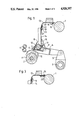
- FIG. 1 illustrates a cross sectional view of a lap guide arrangement in a combing machine in accordance with the invention
- FIG. 2 illustrates a cross sectional view of the lap guide arrangement in a delivery position of the nipper
- FIG. 3 illustrates a part cross sectional view of an alternative mounting of the lap guide arrangement adjacent the lap roller.
- the combing machine comprises a rotating lap roller 1, a rotating comb cylinder shaft 2, a nipper shaft 3 rotatable with an oscillating movement and two detaching rollers 4, all mounted in a machine frame (not shown).
- the front end of the lower nippier jaw 6 is articulated on links 7 mounted to pivot about the axis of the comb cylinder shaft 2.
- An upper nipper jaw 8 co-operates with the lower nipper jaw 6 and is connected to the latter to pivot about a pivot 9.
- An intermittently rotatable feed roller 10 is mounted in the lower nipper jaw 6.
- the continuously rotating comb cylinder shaft 2 conventionally carries a comb cylinder 11 with a comb cylinder segment 12 bearing combing teeth.
- a lap guide arrangement formed by a pair of guide plates 13, 14 is disposed between the lap roller 1 and the feed roller 10 to guide the lap.
- the lap for combing which has a width of about 30 centimeters (cm) for example, lies (not shown) on the lap roller 1.
- Rotation of the lap roller 1 causes the lap to be unwound and fed to the first guide plate 13.
- the lap then passes over the first guide plate 13 and the second guide plate 14 to the feed roller 10 and from the latter to a nip K (FIG. 1) between the upper and lower nipper jaws 6, 8.
- the nipper 6, 8 In the withdrawn position of the lower nipper jaw 6 as shown in FIG. 1, the nipper 6, 8 is closed and the lap is nipped in the nip K. A tuft projecting from the nip K is combed out by the rotating comb cylinder segment 12 in known manner. The nipper is then advanced into the position shown in FIG. 2, the nipper jaws 6, 8 opening in these conditions. The tuft combed out by the comb cylinder segment 12 is received by the detaching rollers 4 and pulled through a top comb (not shown), which is now situated in front of the detaching rollers. The lower nipper jaw 6 then returns to the withdrawn position, and the cycle starts afresh.
- the two guide plates 13 and 14 ensure that the distance covered by the lap between the lap roller 1 and the feed roller 10 always remains of the same length during the described movement of the lower nipper jaw 6 and hence of the feed roller 10.
- the guide plate 13 is pivotally connected adjacent the lap roller 1 via a coupling means having an element 15 which is fixed on the frame at the lap roller 1 and a member 16 fixed on the guide plate 13.
- the element 15 consists of at least one shaft while the member 16 is snapped onto the shaft 15.
- the element 15 fixed to the frame may, for example, be a shaft extending over the entire width of the guide plate 13, onto which shaft one or more members 16 fixed on the guide plate 13 are snapped.
- a shorter shaft 15 fixed on the frame may be disposed at each of the two side edges of the guide plate 13 and have a member 16 snapped on each of them.
- the second guide plate 14 is pivotally connected at its bottom edge by a coupling means having an element 17 disposed at the feed roller 10 and held on the lower nipper jaw and a cooperating member 18 on the guide plate 14.
- the element 17 may again consist, for example, of at least one shaft onto which the member 18 is snapped.
- the guide plates 13, 14 are pivotally connected by means of at least one strip 19 of flexible material fixed on the two plates 13, 14 in the region of the bottom edge of the plate 13 and in the region of the adjacent top edge of the plate 14 respectively, e.g. by clamping strips 20 and 21, through which countersunk screws 22 and 23 are passed and threaded into holes in the plates 13, 14 in threaded relation.
- the strip 19 is preferably a strip measuring about 3 centimeters ⁇ 30 centimeters (cm) extending substantially continuously over the entire width of the plates 13, 14.
- the width of the strip 19 may generally advantageously be between about 2 and 5 centimeters (cm). Instead of the continuous strip, however, a plurality of separate shorter strips could be used, being distributed over the width of the plates 13, 14.
- the thickness of the strip 19 may be about 0.5 to 2.5 millimeters (mm), preferably 1.0 to 1.5 millimeters (mm).
- the bottom edge of the first guide plate 13 has a small distance of about 1 to 5 millimeters (mm), preferably 2 to 3 millimeters (mm), from the top edge of the second guide plate 14; the strip 19 can deflect freely over this distance.
- the strip 19 consists of a flexible material of high tensile strength of the kind used, for example, for driving belts, e.g. of plastics or an industrial fabric, preferably a fabric of polyamide filaments, such as nylon, or aramide or para-aramide filaments, suich as "KEVLAR".
- a fabric of this kind may be coated with a plastics material or be present as a reinforcement in a plastics strip.
- the coupling means the coupling the guide plates 13, 14 into the combining machine may employ at least one strip of flexible material.
- a mounting plate 24 is fixedly mounted in the frame adjacent to the lap roller 1 and a strip 25 of flexible material is fixed to the plate 24, as above, by a clamping plate and screws as well as to the guide plate 13 in similar manner.
- the strip 25 of flexible material may be made of the same material as the strip 19 described above.
- the invention thus provides a lap guide arrangement which is capable of flexing at a high number of nips, for example, at nip numbers of from 300 to 350.
- the flexible strip 19 imparts a relatively long useful life to guide arrangement.
- the strip of flexible material also requires no lubrication and generates no noise during operation. This further increases the aesthetic requirements of a lap guide arrangement.
Landscapes
- Engineering & Computer Science (AREA)
- Textile Engineering (AREA)
- Preliminary Treatment Of Fibers (AREA)
Applications Claiming Priority (2)
| Application Number | Priority Date | Filing Date | Title |
|---|---|---|---|
| CH01425/88 | 1988-04-19 | ||
| CH142588 | 1988-04-19 |
Publications (1)
| Publication Number | Publication Date |
|---|---|
| US4928357A true US4928357A (en) | 1990-05-29 |
Family
ID=4210162
Family Applications (1)
| Application Number | Title | Priority Date | Filing Date |
|---|---|---|---|
| US07/333,459 Expired - Lifetime US4928357A (en) | 1988-04-19 | 1989-04-05 | Lap guide arrangement for a combing machine |
Country Status (5)
| Country | Link |
|---|---|
| US (1) | US4928357A (de) |
| EP (1) | EP0338300B1 (de) |
| JP (1) | JP2635761B2 (de) |
| DD (1) | DD280561A5 (de) |
| DE (1) | DE58901371D1 (de) |
Cited By (5)
| Publication number | Priority date | Publication date | Assignee | Title |
|---|---|---|---|---|
| US4970851A (en) * | 1988-08-12 | 1990-11-20 | Rieter Machine Works Ltd. | Combing machine |
| US5062183A (en) * | 1989-07-20 | 1991-11-05 | Rieter Machine Works Limited | Lap feed plate connected to oscillating nippers in a combing machine |
| CN102953167A (zh) * | 2012-11-14 | 2013-03-06 | 经纬纺织机械股份有限公司 | 精梳机可调式导棉板装置 |
| CN105671696A (zh) * | 2016-02-22 | 2016-06-15 | 经纬纺织机械股份有限公司 | 精梳机弹性张力板 |
| US20170121864A1 (en) * | 2015-11-02 | 2017-05-04 | Kabushiki Kaisha Toyota Jidoshokki | Method and device for cutting lap in comber |
Families Citing this family (2)
| Publication number | Priority date | Publication date | Assignee | Title |
|---|---|---|---|---|
| JP2763968B2 (ja) | 1990-05-02 | 1998-06-11 | マシーネンフアブリーク リーテル アクチエンゲゼルシヤフト | ラップ処理機械におけるラップの接合方法及びラップ処理機械 |
| CH709900A2 (de) * | 2014-07-21 | 2016-01-29 | Rieter Ag Maschf | Kämmmaschine. |
Citations (5)
| Publication number | Priority date | Publication date | Assignee | Title |
|---|---|---|---|---|
| GB190918130A (en) * | 1909-08-06 | 1910-06-09 | James Jolly | Improvements in Combing Machines. |
| US1087780A (en) * | 1911-05-24 | 1914-02-17 | John B Livsey | Combing-machine. |
| DE868865C (de) * | 1950-03-21 | 1953-03-02 | Alsacienne Constr Meca | Speisevorrichtung fuer Textilmaschinen, insbesondere Kaemmaschinen |
| US3320633A (en) * | 1965-08-25 | 1967-05-23 | Du Pont | Apparatus for forming two component yarns |
| GB1414578A (en) * | 1973-02-08 | 1975-11-19 | Tematex Spa | Feeding combing machines |
Family Cites Families (1)
| Publication number | Priority date | Publication date | Assignee | Title |
|---|---|---|---|---|
| GB1047692A (en) * | 1962-05-07 | 1966-11-09 | Howa Machinery Ltd | Cotton combers |
-
1989
- 1989-04-01 DE DE8989105756T patent/DE58901371D1/de not_active Expired - Lifetime
- 1989-04-01 EP EP89105756A patent/EP0338300B1/de not_active Expired - Lifetime
- 1989-04-05 US US07/333,459 patent/US4928357A/en not_active Expired - Lifetime
- 1989-04-17 DD DD89327695A patent/DD280561A5/de not_active IP Right Cessation
- 1989-04-19 JP JP1097685A patent/JP2635761B2/ja not_active Expired - Fee Related
Patent Citations (5)
| Publication number | Priority date | Publication date | Assignee | Title |
|---|---|---|---|---|
| GB190918130A (en) * | 1909-08-06 | 1910-06-09 | James Jolly | Improvements in Combing Machines. |
| US1087780A (en) * | 1911-05-24 | 1914-02-17 | John B Livsey | Combing-machine. |
| DE868865C (de) * | 1950-03-21 | 1953-03-02 | Alsacienne Constr Meca | Speisevorrichtung fuer Textilmaschinen, insbesondere Kaemmaschinen |
| US3320633A (en) * | 1965-08-25 | 1967-05-23 | Du Pont | Apparatus for forming two component yarns |
| GB1414578A (en) * | 1973-02-08 | 1975-11-19 | Tematex Spa | Feeding combing machines |
Cited By (6)
| Publication number | Priority date | Publication date | Assignee | Title |
|---|---|---|---|---|
| US4970851A (en) * | 1988-08-12 | 1990-11-20 | Rieter Machine Works Ltd. | Combing machine |
| US5062183A (en) * | 1989-07-20 | 1991-11-05 | Rieter Machine Works Limited | Lap feed plate connected to oscillating nippers in a combing machine |
| CN102953167A (zh) * | 2012-11-14 | 2013-03-06 | 经纬纺织机械股份有限公司 | 精梳机可调式导棉板装置 |
| US20170121864A1 (en) * | 2015-11-02 | 2017-05-04 | Kabushiki Kaisha Toyota Jidoshokki | Method and device for cutting lap in comber |
| US10208406B2 (en) * | 2015-11-02 | 2019-02-19 | Kabushiki Kaisha Toyota Jidoshokki | Method and device for cutting lap in comber |
| CN105671696A (zh) * | 2016-02-22 | 2016-06-15 | 经纬纺织机械股份有限公司 | 精梳机弹性张力板 |
Also Published As
| Publication number | Publication date |
|---|---|
| JP2635761B2 (ja) | 1997-07-30 |
| EP0338300B1 (de) | 1992-05-13 |
| DD280561A5 (de) | 1990-07-11 |
| DE58901371D1 (de) | 1992-06-17 |
| JPH01306627A (ja) | 1989-12-11 |
| EP0338300A1 (de) | 1989-10-25 |
Similar Documents
| Publication | Publication Date | Title |
|---|---|---|
| JP4116124B2 (ja) | 針布を備えたフラットバーからなる、紡織繊維に対するカードの装置 | |
| GB2435051A (en) | Flat card clothing | |
| US6163931A (en) | Feeding device for advancing fiber material to a fiber processing machine | |
| US7665188B2 (en) | Apparatus on a carding machine for cotton, synthetic fibres and the like, in which at least one flat bar with a flat clothing is present | |
| JPH0578919A (ja) | 針布を備えたフラツトバーからなる移動フラツトを有するカード | |
| CN102348839A (zh) | 回转盖板梳理机 | |
| US4955111A (en) | Travelling flats assembly for a carding machine | |
| US5001815A (en) | Combing cylinder utilized for combing machine | |
| JP2000034623A (ja) | カ―ド、クリ―ナ等の如き紡績準備機に設けた少なくとも1つのカ―ディングセグメントを有する装置 | |
| GB2254344A (en) | Apparatus for cleaning and opening fibre material | |
| JP2635761B2 (ja) | コーミングマシンにおいてラップローラと供給ローラとの間でラップを案内するための装置 | |
| US8332992B2 (en) | Device at a card for cotton, synthetic fibres and the like, in which at least one flat bar having a flat clothing is present | |
| US2686939A (en) | Drawing frame or system comprising an endless belt for conveying the fibrous material in slubbing, roving, and spinning frames | |
| GB1429619A (en) | Textile machines | |
| GB2058847A (en) | Drawing device for a flat knitting machine | |
| US5956811A (en) | Revolving flat card | |
| US5255416A (en) | Combing machine with means for limiting movement of top nipper | |
| US5062183A (en) | Lap feed plate connected to oscillating nippers in a combing machine | |
| US4980952A (en) | Transverse conveyor arrangement at the outlet of a card | |
| US4017942A (en) | Textile carding | |
| CN211895345U (zh) | 预缩机喂布装置及其预缩机 | |
| US5307546A (en) | Apparatus for feeding a fiber batt to a needle loom | |
| EP2452001B1 (de) | Vorrichtung zur bildung eines faserbandes | |
| US4532678A (en) | Needle bar drawing device | |
| JPH08209464A (ja) | フロック状繊維材料の除塵及び開繊装置 |
Legal Events
| Date | Code | Title | Description |
|---|---|---|---|
| AS | Assignment |
Owner name: RIETER MACHINE WORKS, LTD., WINTERTHUR, SWITZERLAN Free format text: ASSIGNMENT OF ASSIGNORS INTEREST.;ASSIGNOR:CLEMENT, HEINZ;REEL/FRAME:005127/0063 Effective date: 19890602 |
|
| STCF | Information on status: patent grant |
Free format text: PATENTED CASE |
|
| CC | Certificate of correction | ||
| FEPP | Fee payment procedure |
Free format text: PAYOR NUMBER ASSIGNED (ORIGINAL EVENT CODE: ASPN); ENTITY STATUS OF PATENT OWNER: LARGE ENTITY |
|
| FPAY | Fee payment |
Year of fee payment: 4 |
|
| FPAY | Fee payment |
Year of fee payment: 8 |
|
| FPAY | Fee payment |
Year of fee payment: 12 |