US4933588A - Higher order transverse mode suppression in surface acoustic wave resonators - Google Patents
Higher order transverse mode suppression in surface acoustic wave resonators Download PDFInfo
- Publication number
- US4933588A US4933588A US07/289,132 US28913288A US4933588A US 4933588 A US4933588 A US 4933588A US 28913288 A US28913288 A US 28913288A US 4933588 A US4933588 A US 4933588A
- Authority
- US
- United States
- Prior art keywords
- frequency
- mode
- disposed
- fundamental
- resonator
- Prior art date
- Legal status (The legal status is an assumption and is not a legal conclusion. Google has not performed a legal analysis and makes no representation as to the accuracy of the status listed.)
- Expired - Fee Related
Links
- 238000010897 surface acoustic wave method Methods 0.000 title claims abstract description 19
- 230000001629 suppression Effects 0.000 title 1
- 239000000463 material Substances 0.000 claims abstract description 27
- 230000001902 propagating effect Effects 0.000 claims abstract description 10
- 238000000034 method Methods 0.000 claims abstract description 8
- 238000000151 deposition Methods 0.000 claims description 6
- 239000002184 metal Substances 0.000 claims 2
- 238000003780 insertion Methods 0.000 abstract description 38
- 230000037431 insertion Effects 0.000 abstract description 38
- 230000007423 decrease Effects 0.000 abstract description 2
- 230000004075 alteration Effects 0.000 abstract 1
- 238000009966 trimming Methods 0.000 abstract 1
- 238000009826 distribution Methods 0.000 description 6
- 230000000694 effects Effects 0.000 description 4
- 238000001514 detection method Methods 0.000 description 3
- 239000010453 quartz Substances 0.000 description 3
- VYPSYNLAJGMNEJ-UHFFFAOYSA-N silicon dioxide Inorganic materials O=[Si]=O VYPSYNLAJGMNEJ-UHFFFAOYSA-N 0.000 description 3
- XAGFODPZIPBFFR-UHFFFAOYSA-N aluminium Chemical compound [Al] XAGFODPZIPBFFR-UHFFFAOYSA-N 0.000 description 2
- 229910052782 aluminium Inorganic materials 0.000 description 2
- 239000002131 composite material Substances 0.000 description 2
- 239000004020 conductor Substances 0.000 description 2
- 239000013078 crystal Substances 0.000 description 2
- 238000012544 monitoring process Methods 0.000 description 2
- 230000010355 oscillation Effects 0.000 description 2
- 230000010363 phase shift Effects 0.000 description 2
- 230000000087 stabilizing effect Effects 0.000 description 2
- 230000015556 catabolic process Effects 0.000 description 1
- 238000004891 communication Methods 0.000 description 1
- 230000006835 compression Effects 0.000 description 1
- 238000007906 compression Methods 0.000 description 1
- 238000006731 degradation reaction Methods 0.000 description 1
- 230000008021 deposition Effects 0.000 description 1
- 238000010586 diagram Methods 0.000 description 1
- 239000011521 glass Substances 0.000 description 1
- 230000003993 interaction Effects 0.000 description 1
- GQYHUHYESMUTHG-UHFFFAOYSA-N lithium niobate Chemical compound [Li+].[O-][Nb](=O)=O GQYHUHYESMUTHG-UHFFFAOYSA-N 0.000 description 1
- TWNQGVIAIRXVLR-UHFFFAOYSA-N oxo(oxoalumanyloxy)alumane Chemical compound O=[Al]O[Al]=O TWNQGVIAIRXVLR-UHFFFAOYSA-N 0.000 description 1
- 238000005070 sampling Methods 0.000 description 1
- 238000007789 sealing Methods 0.000 description 1
- 230000002459 sustained effect Effects 0.000 description 1
Images


Classifications
-
- H—ELECTRICITY
- H03—ELECTRONIC CIRCUITRY
- H03H—IMPEDANCE NETWORKS, e.g. RESONANT CIRCUITS; RESONATORS
- H03H3/00—Apparatus or processes specially adapted for the manufacture of impedance networks, resonating circuits, resonators
- H03H3/007—Apparatus or processes specially adapted for the manufacture of impedance networks, resonating circuits, resonators for the manufacture of electromechanical resonators or networks
- H03H3/08—Apparatus or processes specially adapted for the manufacture of impedance networks, resonating circuits, resonators for the manufacture of electromechanical resonators or networks for the manufacture of resonators or networks using surface acoustic waves
- H03H3/10—Apparatus or processes specially adapted for the manufacture of impedance networks, resonating circuits, resonators for the manufacture of electromechanical resonators or networks for the manufacture of resonators or networks using surface acoustic waves for obtaining desired frequency or temperature coefficient
-
- Y—GENERAL TAGGING OF NEW TECHNOLOGICAL DEVELOPMENTS; GENERAL TAGGING OF CROSS-SECTIONAL TECHNOLOGIES SPANNING OVER SEVERAL SECTIONS OF THE IPC; TECHNICAL SUBJECTS COVERED BY FORMER USPC CROSS-REFERENCE ART COLLECTIONS [XRACs] AND DIGESTS
- Y10—TECHNICAL SUBJECTS COVERED BY FORMER USPC
- Y10T—TECHNICAL SUBJECTS COVERED BY FORMER US CLASSIFICATION
- Y10T29/00—Metal working
- Y10T29/42—Piezoelectric device making
Definitions
- This invention relates generally to surface acoustic wave devices and more particularly to narrowband surface acoustic wave resonators.
- SAW surface acoustic wave resonators are used in high precision and highly stable, low noise oscillators.
- the SAW device is used as a frequency stabilizing element in the feedback loop of both electronically controlled oscillators and free running oscillators.
- Such oscillators are used in radar systems, electronic counter measure systems, as well as, other communication and electrical systems.
- a low noise, highly stable oscillator is often used to synchronize all the radar signals in phase and frequency.
- One requirement for advanced radar systems is to increase the capability of the radar to detect small objects at further distances. It can be shown that the detection capability of a radar is related to the system noise which is related to the output power and noise characteristics of the oscillator. If more output power can be extracted from an oscillator without increasing the noise level of the oscillator, then the noise floor of the radar system will be reduced. Reduced system noise will increase the signal to noise ratio of the radar and concomitant therewith the detection capabilities of the radar. Thus, it is desireable to provide higher output powers at low noise levels from SAW-stabilized oscillators to reduce the system floor noise of the radar and increase its detection capabilities.
- a SAW resonator generally includes a surface which supports surface acoustic wave propagation having disposed thereon a pair of spaced interdigitated transducers which are coupled to the surface wave propagating surface.
- Each interdigitated transducer includes a pair of terminals having a plurality of conductive members, with the conductive members associated with one terminal being interdigitated with the conductive members associated with the other one of the terminals.
- a pair of reflecting gratings are disposed to confine surface wave propagation as also known.
- SAW resonator having a relatively low insertion loss. This is accomplished as indicated above by increasing the number of conductive strips in the transducer. Reducing insertion loss has the effect of lowering the Q of the resonator and likewise degrades noise characteristics of the resonator.
- Higher order transverse mode propagation includes even order transverse modes and odd order transverse modes.
- the even order transverse modes are generally not a problem, since the phase of even transverse modes is symmetrically distributed occurs across the acoustic aperture of the device.
- the phase of odd order transverse modes is a problem since the phase is symmetrically distributed.
- the acoustic energy stored in the resonant cavity at higher order odd transverse mode has a different spacial distribution than the frequency of the fundamental mode. Further, the resonant frequencies of the higher order transverse modes are higher than the frequency of the fundamental resonant mode.
- the third order transverse mode typically has a magnitude of between about 2-10 dB below the minimum insertion loss of the fundamental mode, and at a frequency of about 50 to 100 ppm higher than the frequency of the fundamental mode.
- the wider aperatures and extra fingers change the frequency and insertion loss characteristics of the third order transverse mode.
- the insertion loss of the third order mode may appear only 1 dB below the insertion loss of the fundamental mode, at a frequency of about 35 ppm above the frequency of the fundamental.
- the fundamental mode frequency is generally determined by its 1 dB bandwith, that is the frequency range over which the insertion is within 1 dB of the minimum insertion loss of the fundamental mode.
- the third order transverse mode may be encompassed within the 1 dB bandwith of the resonator and will significantly decrease the Q of the resonator. This arrangement will degrade the phase noise performance of an oscillator using such a SAW resonator.
- a surface acoustic wave device includes a base having a surface for supporting surface wave propagation, including a pair of transducers coupled to said surface wave propagation surface, and means, disposed over regions of said surface wave propagation surface where an odd order transverse mode has energy maxima, for locally changing the surface wave velocity characteristic in said regions, by adjusting the frequency of the odd order transverse mode to be substantially equal to that of the fundamental transverse mode.
- the frequency of the odd order transverse mode is adjusted to be substantially equal to the frequency of the fundamental mode. This eliminates degradation in phase noise due to presence of these higher order transverse mode in the SAW resonator.
- a surface acoustic wave resonator includes a base having a surface which supports surface acoustic wave propagation including a pair of transducers coupled to said surface acoustic wave propagation surface, said transducers including interdigitated conductive stripes disposed across first selected portions of said surface.
- a cover is disposed over said base to enclose said base. Said cover comprises a material which is optically transparent to electromagnetic energy generally in the wavelength range of about 0.185-4.0 ⁇ m.
- a layer of material is disposed on an inner portion of the cover over said surface wave propagation surface in a region thereof disposed between said pair of transducers.
- First and second selected portions of said layer are disposed on said surface wave propagation surface in regions of said surface where an undesired odd order transverse mode has energy maxima to change the frequency of said odd order transverse mode to be substantially equal to that of the fundamental transverse mode.
- the SAW resonator will have improved bandpass characteristics, and reduced insertion loss at the fundamental frequency and be more useful for voltage control oscillator and free-running oscillator applications. Further, the insertion loss at the fundamental is reduced and the Q is increased because the frequency of third order transverse mode is shifted to be substantially equal to that of the fundamental mode, increasing energy of the device at the frequency of the fundamental mode.
- a method of improving the bandpass characteristic of a SAW resonator comprises the step of depositing a pair of layers of material over a pair of selected portions of the surface wave propagation surface to change the frequency of a selected higher order transverse mode of said resonator.
- a surface acoustic wave resonator includes a base having a surface which supports surface acoustic wave propagation including a pair of transducers coupled to said surface acoustic wave propagation surface, with said transducers including interdigitated conductive stripes disposed across first selected portions of said surface.
- a cover is disposed over said base to enclose said base.
- Said cover comprises a material which is optically transparent to electromagnetic energy generally in the wavelength range of about 0.185-4.0 ⁇ m.
- a layer of material is disposed on an inner portion of the cover over said surface wave propagation surface in a region thereof disposed between said pair of transducers.
- First and second selected portions of said layer are disposed on said surface wave propagation surface partially across said aperture, where an undesired odd order transverse mode has energy maxima to change the frequency of said odd order transverse mode to be substantially equal to that of the fundamental mode transverse wave.
- a third portion of said layer of material is disposed on said surface acoustic wave propagation surface across the acoustic aperture of said SAW device to change both the fundamental frequency of the device and the suppressed higher order transverse mode frequency of the device to tune the SAW resonator to a desired frequency characteristic.
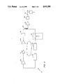
- FIG. 1 is a block diagram of a voltage controlled oscillator utilizing a SAW resonator as a frequency stabilizing element
- FIG. 2 is a plan view of a SAW resonator which may be used in the SAW stabilized oscillator of FIG. 1 fabricated in accordance with the present invention
- FIG. 3 is a cross-sectional view taken along lines 3--3 of FIG. 2;
- FIG. 4 is an exploded, enlarged view of a portion of FIG. 3 taken along ling 4--4 of FIG. 3;
- FIG. 5 is a diagrammatical view showing typical relationships of the distributions of energy for the fundamental transverse mode, and the third order transverse mode across the acoustic aperture of a typical SAW resonator;
- FIG. 6 is the SAW resonator of FIG. 2 having a layer disposed to change the fundamental frequency of the resonator;
- FIG. 7 is a cross-sectional view taken along lines 7--7 of FIG. 6;
- FIG. 8 is an exploded, enlarged view of FIG. 7 taken along line 8--8 of FIG. 7;
- FIG. 9 is a plot of magnitude vs. frequency for the magnitude and phase of the fundamental mode of a standard SAW resonator having a third order transverse mode
- FIG. 10A is a plot of magnitude vs. frequency for the magnitude of the fundamental mode of a higher power SAW resonator having a third order transverse mode about within the 1 db bandwidth of the fundamental mode;
- FIG. 10B is a plot of the device of FIG. 10A having the third order transverse mode adjusted in accordance with an aspect of the present invention.
- a voltage controlled, SAW resonator stabilized, low floor noise oscillator 10 is shown to include low noise components such as a feedback loop 13 comprising loop amplifiers 12a and 12b, a voltage controlled oscillator 14, a voltage limiter 16, a loop signal sampling coupler 24, an attenuator 18, a SAW resonator 30, and a coarse loop phase adjustment means 22 as shown.
- the SAW resonator 30 is used in the feedback loop 13 around amplifiers 12a and 12b to provide the requisite phase shift characteristics of the signal propagating in the feedback loop and to stabilize the frequency of the signal generated by said loop.
- the electronic phase shifter 18 is used to electrically fine tune the frequency of the oscillator 10 over a predetermined bandwidth.
- the limiter 16, attenuator 18, and the loop phase adjustment 22 are also provided to make adjustments in the loop characteristics of the oscillator 10. As is known, sustained oscillations will be provided at a frequency where the amplifiers provide sufficient gain to compensate for losses in the feedback loop, and where the loop has a phase characteristics equal to a multiple of 2 ⁇ radians.
- the electronic phase shifter 14 provides a relatively small variable phase shift to the characteristics and thus electronically changes the frequency of the oscillator 10.
- the output signal at the output of coupler 24 is fed to a buffer amplifier 25 which is used to prevent loading of the oscillator from the remainder of the circuit.
- this signal may be fed through a low pass filter 26 to improve the purity of the signal before being coupled to the output terminal 27 of the oscillator 10.
- the output signal is fed to a load 29 which here may be a radar system.
- FIG. 1 A preferred embodiment for the SAW resonator 30 useful for a low noise floor oscillator circuit 10 as shown in FIG. 1 will now be described in conjunction with FIGS. 2-4.
- the SAW resonator 30 is here shown to include a base 31 having a surface 31a which supports surface wave propagation.
- said base 31 is comprised of an ST-cut or a rotated ST-cut of quartz although other materials (such as lithium niobate) may alternatively be used.
- transducers 32, 34 Disposed on quartz base 31 are here a pair of transducers 32, 34 with here transducer 32 being an input transducer, and transducer 34 being an output transducer.
- Each one of said transducers include a pair of terminals 32', 32"' and 34', 34" and a plurality of conductive stripes or strip conductors 32a, 32a' and 34a, 34a, as shown.
- transducer 32 includes a pair of conductive terminals 32', 32" with each one of said conductor terminals connecting a plurality of conductive stripes 32a, 32a', said stripes being interdigitated.
- said stripes are comprised of aluminum and are recessed into grooves provided in the SAW surface 31a. That is, the stripes from terminal 32' are disposed across the surface 31a and alternately spaced between corresponding stripes from terminal 32".
- Resonator 30 further includes a pair of reflecting gratings, here 35a, 35b which are here comprised of a plurality of slots or grooves disposed in the surface 31a.
- the resonator 13 is sealed in an all-quartz package and includes a sealing member 37 here comprised of a glass frit and a cover member 38 here comprised of a material crystallographically matched to the material of the base 31. Disposed on an inner portion of cover 38 is a pad 39 here comprised of a tri-level film as will be described.
- pads 40' and 40" are shown disposed on surface 31a. Pads 40' and 40" are used to provide small localized changes in the surface wave velocity characteristic across a relatively small portion of the acoustic aperture of the device 10 to permit tuning of the third order transverse mode frequency without significantly changing the frequency of the fundamental transverse mode.
- tuning is accomplished by reducing the frequency of the third order transverse mode such that it is substantially equal to the frequency of the fundamental transverse mode.
- Pad 39 which is disposed over an inner portion of cover 38 is here a tri-level composite pad and includes a thermally insulating buffer layer 39a, a thermal radiating layer 39b, and a thermally ablatable layer 39c, with here layers 39a and 39c being comprised of aluminum oxide and layer 39b being comprised of aluminum.
- Incident laser energy 50 is directed through the cover 38 and layer 39a to layer 39b to provide a localized heated region thereof, which is used to ablate off a portion of the composite layer 39 to provide deposits 40' or 40" as shown.
- FIG. 5 shows the energy distribution across the acoustic aperture of the fundamental transverse mode propagation 72 and for the third order transverse mode 74.
- the active length of the interdigitated conductive members 32 that is the area over which the conductive members transversally overlap is defined as the active or acoustic aperture of the device and is denoted in FIG. 5 by the reference AA.
- the surface acoustic wave device operates by feeding an input signal to the input transducer 32, which provides an electrical potential across the electrode terminals 32', 32". This causes crystal structure deformation in the surface acoustic wave surface 31a. This deformation propagates as a transverse wave along the surface wave device 30 to the output terminal 34. The wave is confined by the reflecting gratings 35a, 35b and is coupled to the output pair of electrodes 34', 34" of transducer 34. The alternating compression and rarification of the crystal structure of the surface acoustic wave through the piezoelectric interaction produces corresponding voltage fluctuations across the electrodes 34', 34", thereby providing a replica of the signal coupled to the transducer 32.
- FIGS. 10A and 10B the frequency characteristics of standard type of SAW resonator (FIG. 9) and a high power SAW resonator are shown in FIGS. 10A and 10B.
- FIG. 9 shows the insertion loss characteristic for a standard SAW resonator.
- the insertion loss as a function of frequency for the fundamental mode is shown as curve 50.
- the third order transverse mode occurs as the perturbation 52 in curve 50.
- the insertion loss of this perturbation is approximately 7 dB higher than that at the fundamental 51.
- the frequency of this perturbation is approximated 100 ppm higher than the frequency of the fundamental mode.
- This characteristic was provided from a standard SAW resonator having a center frequency of 402.171 MHz and having transducers with 51 fingers each, and with each finger 150 acoustic wavelengths long.
- FIG. 10A shows the insertion loss characteristic as a function of frequency for a higher power-lower loss SAW resonator having transducers with 61 fingers and an acoustic aperture or finger length equal to 200 acoustic wavelengths.
- the insertion loss characteristic 60 has a minimum loss at 61 which corresponds to the center frequency of the SAW resonator.
- the third order transverse mode provides a perturbation at 62 which has an insertion loss only 1 dB higher than the minimum insertion loss of the fundamental transverse mode 61.
- the frequency is shifted closer to the frequency at the fundamental, that is being within approximately 35 ppm of the frequency of the fundamental.
- the pads 40' and 40" each having a length across the aperture of about 15% of the acoustic aperture and are located starting at a distance of about 10% away from the edges of the acoustic aperture.
- a preferred technique for suppressing the third order transverse mode wave propagation is to insert the completed SAW device in a network analyzer and monitor the insertion loss characteristic about the center frequency range of the SAW device. During such monitoring, a characteristic as shown in FIG. 10A will appear, having a minimum insertion loss characteristic denoted at 72 of curve 70 which corresponds to the insertion loss characteristic for the fundamental transverse mode.
- the material deposits 40' and 40" are provided by application of an excimer laser beam through the cover to ablate off selected portions of pad 39 onto the surface wave propagation surface. If material is deposited in the correct locations (i.e.
- the perturbation 74 will move closer to the minimum insertion loss at 72 until the energy of the third order mode is added to that of the fundlemental. If it were desired to surpress the fifth order transversal, more generally four deposits (not shown) would be used, again the deposits would be disposed away from the center of the acoustic aperture.
- the fundamental mode frequency may be selectively altered to provide a selected shift in the frequency characteristic thereof.
- a single line of material 42 is shown deposited across the entire acoustic aperture of the surface wave device on surface wave propagation surface 41.
- Layer 42 provides a localized region of change of surface wave velocity characteristic across the entire acoustic aperture to tune the frequency fundamental transverse mode and thus selectively change the center frequency of the device.
Landscapes
- Physics & Mathematics (AREA)
- Acoustics & Sound (AREA)
- Engineering & Computer Science (AREA)
- Manufacturing & Machinery (AREA)
- Surface Acoustic Wave Elements And Circuit Networks Thereof (AREA)
- Oscillators With Electromechanical Resonators (AREA)
Priority Applications (4)
| Application Number | Priority Date | Filing Date | Title |
|---|---|---|---|
| US07/289,132 US4933588A (en) | 1988-12-23 | 1988-12-23 | Higher order transverse mode suppression in surface acoustic wave resonators |
| DE68919662T DE68919662T2 (de) | 1988-12-23 | 1989-12-19 | Unterdrückung von transversalen Moden höherer Ordnung in akustischen Oberflächenwellenresonatoren. |
| EP89313280A EP0375360B1 (en) | 1988-12-23 | 1989-12-19 | Higher order transverse mode suppression in surface acoustic wave resonators |
| JP1334643A JPH02224514A (ja) | 1988-12-23 | 1989-12-22 | 表面弾性波デバイス及び高次横モード抑制方法 |
Applications Claiming Priority (1)
| Application Number | Priority Date | Filing Date | Title |
|---|---|---|---|
| US07/289,132 US4933588A (en) | 1988-12-23 | 1988-12-23 | Higher order transverse mode suppression in surface acoustic wave resonators |
Publications (1)
| Publication Number | Publication Date |
|---|---|
| US4933588A true US4933588A (en) | 1990-06-12 |
Family
ID=23110186
Family Applications (1)
| Application Number | Title | Priority Date | Filing Date |
|---|---|---|---|
| US07/289,132 Expired - Fee Related US4933588A (en) | 1988-12-23 | 1988-12-23 | Higher order transverse mode suppression in surface acoustic wave resonators |
Country Status (4)
| Country | Link |
|---|---|
| US (1) | US4933588A (ja) |
| EP (1) | EP0375360B1 (ja) |
| JP (1) | JPH02224514A (ja) |
| DE (1) | DE68919662T2 (ja) |
Cited By (25)
| Publication number | Priority date | Publication date | Assignee | Title |
|---|---|---|---|---|
| WO1991007782A1 (en) * | 1989-11-13 | 1991-05-30 | X-Cyte, Inc. | Inductively coupled saw device and method for making the same |
| US5059848A (en) * | 1990-08-20 | 1991-10-22 | The United States Of America As Represented By The Secretary Of The Army | Low-cost saw packaging technique |
| US5138214A (en) * | 1989-12-27 | 1992-08-11 | Matsushita Electric Industrial Co., Ltd. | Piezoelectric transducer and method of adjusting oscillation frequency thereof |
| US5196753A (en) * | 1989-07-31 | 1993-03-23 | Raytheon Company | Surface acoustic wave devices having long-term frequency stability |
| US5208504A (en) * | 1990-12-28 | 1993-05-04 | Raytheon Company | Saw device and method of manufacture |
| US5216312A (en) * | 1992-02-28 | 1993-06-01 | Hewlett-Packard Company | Fluid sensing device having reduced attenuation of shear transverse waves |
| US5274345A (en) * | 1992-05-13 | 1993-12-28 | Andersen Laboratories | Dual function reflector structures for interdigital saw transducer |
| US5319326A (en) * | 1991-04-11 | 1994-06-07 | Siemens Matsushita Comp. Gmbh & Co Kg | Surface-wave-type reflective delay line |
| US5401544A (en) * | 1991-09-25 | 1995-03-28 | Sumitomo Electric Industries, Ltd. | Method for manufacturing a surface acoustic wave device |
| US5416447A (en) * | 1993-11-08 | 1995-05-16 | Raytheon Company | Saw device and method of manufacture |
| US5450747A (en) * | 1993-12-27 | 1995-09-19 | International Business Machines Corporation | Method for optimizing piezoelectric surface asperity detection sensor |
| US5757250A (en) * | 1995-03-06 | 1998-05-26 | Matsushita Electric Industrial Co., Ltd. | Surface acoustic wave module with thin film for wave transmission velocity differentiation |
| US5986382A (en) | 1997-08-18 | 1999-11-16 | X-Cyte, Inc. | Surface acoustic wave transponder configuration |
| US6018211A (en) * | 1993-04-28 | 2000-01-25 | Matsushita Electric Industrial Co., Ltd. | Surface acoustic wave device and method of manufacturing the same |
| US6060815A (en) | 1997-08-18 | 2000-05-09 | X-Cyte, Inc. | Frequency mixing passive transponder |
| US6107910A (en) | 1996-11-29 | 2000-08-22 | X-Cyte, Inc. | Dual mode transmitter/receiver and decoder for RF transponder tags |
| US6114971A (en) | 1997-08-18 | 2000-09-05 | X-Cyte, Inc. | Frequency hopping spread spectrum passive acoustic wave identification device |
| US6208062B1 (en) | 1997-08-18 | 2001-03-27 | X-Cyte, Inc. | Surface acoustic wave transponder configuration |
| US20030020365A1 (en) * | 2001-07-26 | 2003-01-30 | Matsushita Electric Industrial Co., Ltd. | Piezoelectric thin film vibrator and method of adjusting its frequency |
| US6604266B1 (en) * | 1997-06-24 | 2003-08-12 | Tdk Corporation | Manufacturing method for a piezoelectric component |
| US6750460B2 (en) | 2000-05-02 | 2004-06-15 | Epion Corporation | System and method for adjusting the properties of a device by GCIB processing |
| US20050184622A1 (en) * | 2001-02-13 | 2005-08-25 | Murata Manufacturing Co., Ltd. | Surface acoustic wave device and frequency adjustment method of the same |
| US20060086188A1 (en) * | 2004-10-21 | 2006-04-27 | Honeywell International, Inc. | Vacuum sealed surface acoustic wave pressure sensor |
| US20070164842A1 (en) * | 2006-01-19 | 2007-07-19 | Lumera Corporation | Electro-Optic Radiometer to Detect Radiation |
| US20090200894A1 (en) * | 2006-11-24 | 2009-08-13 | Murata Manufacturing Co., Ltd. | Boundary acoustic wave device manufacturing method and boundary acoustic wave device |
Families Citing this family (12)
| Publication number | Priority date | Publication date | Assignee | Title |
|---|---|---|---|---|
| WO2010077311A1 (en) | 2008-12-17 | 2010-07-08 | Sand9, Inc. | Multi-port mechanical resonating devices and related methods |
| US8689426B2 (en) | 2008-12-17 | 2014-04-08 | Sand 9, Inc. | Method of manufacturing a resonating structure |
| WO2010090731A2 (en) * | 2009-02-04 | 2010-08-12 | Sand9, Inc. | Methods and apparatus for tuning devices having mechanical resonators |
| US8456250B2 (en) | 2009-02-04 | 2013-06-04 | Sand 9, Inc. | Methods and apparatus for tuning devices having resonators |
| US8395456B2 (en) | 2009-02-04 | 2013-03-12 | Sand 9, Inc. | Variable phase amplifier circuit and method of use |
| US8604888B2 (en) | 2009-12-23 | 2013-12-10 | Sand 9, Inc. | Oscillators having arbitrary frequencies and related systems and methods |
| US8736388B2 (en) | 2009-12-23 | 2014-05-27 | Sand 9, Inc. | Oscillators having arbitrary frequencies and related systems and methods |
| US8704604B2 (en) | 2009-12-23 | 2014-04-22 | Sand 9, Inc. | Oscillators having arbitrary frequencies and related systems and methods |
| US8661899B2 (en) | 2010-03-01 | 2014-03-04 | Sand9, Inc. | Microelectromechanical gyroscopes and related apparatus and methods |
| WO2011133682A1 (en) | 2010-04-20 | 2011-10-27 | Guiti Zolfagharkhani | Microelectromechanical gyroscopes and related apparatus and methods |
| WO2012040043A1 (en) | 2010-09-20 | 2012-03-29 | Sand9, Inc. | Resonant sensing using extensional modes of a plate |
| US9383208B2 (en) | 2011-10-13 | 2016-07-05 | Analog Devices, Inc. | Electromechanical magnetometer and applications thereof |
Citations (7)
| Publication number | Priority date | Publication date | Assignee | Title |
|---|---|---|---|---|
| US3581248A (en) * | 1969-03-26 | 1971-05-25 | Zenith Radio Corp | Acoustic filters |
| US3818379A (en) * | 1972-12-04 | 1974-06-18 | Hughes Aircraft Co | Acoustic surface wave device |
| US3908137A (en) * | 1973-12-26 | 1975-09-23 | Magnavox Co | Apparatus and method for triple transit signal cancellation in an acoustical surface wave device |
| US4204178A (en) * | 1977-04-07 | 1980-05-20 | U.S. Philips Corporation | Acoustic wave devices |
| US4243960A (en) * | 1978-08-14 | 1981-01-06 | The United States Of America As Represented By The Secretary Of The Navy | Method and materials for tuning the center frequency of narrow-band surface-acoustic-wave (SAW) devices by means of dielectric overlays |
| US4434383A (en) * | 1981-02-09 | 1984-02-28 | Motorola Inc. | Temperature stable surface acoustic wave device |
| US4757283A (en) * | 1987-04-24 | 1988-07-12 | Raytheon Company | Technique for frequency trimming of a saw device using dielectric layers disposed between a pair of transducers of the saw device |
Family Cites Families (5)
| Publication number | Priority date | Publication date | Assignee | Title |
|---|---|---|---|---|
| US4060777A (en) * | 1976-05-19 | 1977-11-29 | Piezo Technology Inc. | Guided elastic surface wave filter |
| US4331943A (en) * | 1980-12-22 | 1982-05-25 | Hewlett-Packard Company | Acoustic wave devices having transverse mode distortions eliminated structurally |
| US4435441A (en) * | 1982-12-30 | 1984-03-06 | The United States Of America As Represented By The Secretary Of The Army | Method of frequency trimming surface acoustic wave devices |
| DE8312016U1 (de) * | 1983-04-22 | 1988-07-14 | Siemens AG, 1000 Berlin und 8000 München | Oberflächenwellen-Resonatorfilter |
| GB2199985B (en) * | 1986-12-22 | 1991-09-11 | Raytheon Co | Surface acoustic wave device |
-
1988
- 1988-12-23 US US07/289,132 patent/US4933588A/en not_active Expired - Fee Related
-
1989
- 1989-12-19 DE DE68919662T patent/DE68919662T2/de not_active Expired - Fee Related
- 1989-12-19 EP EP89313280A patent/EP0375360B1/en not_active Expired - Lifetime
- 1989-12-22 JP JP1334643A patent/JPH02224514A/ja active Pending
Patent Citations (7)
| Publication number | Priority date | Publication date | Assignee | Title |
|---|---|---|---|---|
| US3581248A (en) * | 1969-03-26 | 1971-05-25 | Zenith Radio Corp | Acoustic filters |
| US3818379A (en) * | 1972-12-04 | 1974-06-18 | Hughes Aircraft Co | Acoustic surface wave device |
| US3908137A (en) * | 1973-12-26 | 1975-09-23 | Magnavox Co | Apparatus and method for triple transit signal cancellation in an acoustical surface wave device |
| US4204178A (en) * | 1977-04-07 | 1980-05-20 | U.S. Philips Corporation | Acoustic wave devices |
| US4243960A (en) * | 1978-08-14 | 1981-01-06 | The United States Of America As Represented By The Secretary Of The Navy | Method and materials for tuning the center frequency of narrow-band surface-acoustic-wave (SAW) devices by means of dielectric overlays |
| US4434383A (en) * | 1981-02-09 | 1984-02-28 | Motorola Inc. | Temperature stable surface acoustic wave device |
| US4757283A (en) * | 1987-04-24 | 1988-07-12 | Raytheon Company | Technique for frequency trimming of a saw device using dielectric layers disposed between a pair of transducers of the saw device |
Cited By (38)
| Publication number | Priority date | Publication date | Assignee | Title |
|---|---|---|---|---|
| US5196753A (en) * | 1989-07-31 | 1993-03-23 | Raytheon Company | Surface acoustic wave devices having long-term frequency stability |
| US5095240A (en) * | 1989-11-13 | 1992-03-10 | X-Cyte, Inc. | Inductively coupled saw device and method for making the same |
| WO1991007782A1 (en) * | 1989-11-13 | 1991-05-30 | X-Cyte, Inc. | Inductively coupled saw device and method for making the same |
| US5138214A (en) * | 1989-12-27 | 1992-08-11 | Matsushita Electric Industrial Co., Ltd. | Piezoelectric transducer and method of adjusting oscillation frequency thereof |
| US5059848A (en) * | 1990-08-20 | 1991-10-22 | The United States Of America As Represented By The Secretary Of The Army | Low-cost saw packaging technique |
| US5208504A (en) * | 1990-12-28 | 1993-05-04 | Raytheon Company | Saw device and method of manufacture |
| US5319326A (en) * | 1991-04-11 | 1994-06-07 | Siemens Matsushita Comp. Gmbh & Co Kg | Surface-wave-type reflective delay line |
| US5401544A (en) * | 1991-09-25 | 1995-03-28 | Sumitomo Electric Industries, Ltd. | Method for manufacturing a surface acoustic wave device |
| US5216312A (en) * | 1992-02-28 | 1993-06-01 | Hewlett-Packard Company | Fluid sensing device having reduced attenuation of shear transverse waves |
| US5274345A (en) * | 1992-05-13 | 1993-12-28 | Andersen Laboratories | Dual function reflector structures for interdigital saw transducer |
| US6018211A (en) * | 1993-04-28 | 2000-01-25 | Matsushita Electric Industrial Co., Ltd. | Surface acoustic wave device and method of manufacturing the same |
| US5416447A (en) * | 1993-11-08 | 1995-05-16 | Raytheon Company | Saw device and method of manufacture |
| US5581021A (en) * | 1993-12-27 | 1996-12-03 | International Business Machines Corporation | Method and apparatus for optimizing piezoelectric surface asperity detection sensor |
| US5450747A (en) * | 1993-12-27 | 1995-09-19 | International Business Machines Corporation | Method for optimizing piezoelectric surface asperity detection sensor |
| US5757250A (en) * | 1995-03-06 | 1998-05-26 | Matsushita Electric Industrial Co., Ltd. | Surface acoustic wave module with thin film for wave transmission velocity differentiation |
| US5815900A (en) * | 1995-03-06 | 1998-10-06 | Matsushita Electric Industrial Co., Ltd. | Method of manufacturing a surface acoustic wave module |
| US5996199A (en) * | 1995-03-06 | 1999-12-07 | Matsushita Electric Industrial Co., Ltd. | Method of manufacturing surface acoustic ware modules |
| US7741956B1 (en) | 1996-11-29 | 2010-06-22 | X-Cyte, Inc. | Dual mode transmitter-receiver and decoder for RF transponder tags |
| US6531957B1 (en) * | 1996-11-29 | 2003-03-11 | X-Cyte, Inc. | Dual mode transmitter-receiver and decoder for RF transponder tags |
| US6107910A (en) | 1996-11-29 | 2000-08-22 | X-Cyte, Inc. | Dual mode transmitter/receiver and decoder for RF transponder tags |
| US6950009B1 (en) | 1996-11-29 | 2005-09-27 | X-Cyte, Inc. | Dual mode transmitter/receiver and decoder for RF transponder units |
| US6604266B1 (en) * | 1997-06-24 | 2003-08-12 | Tdk Corporation | Manufacturing method for a piezoelectric component |
| US6060815A (en) | 1997-08-18 | 2000-05-09 | X-Cyte, Inc. | Frequency mixing passive transponder |
| US5986382A (en) | 1997-08-18 | 1999-11-16 | X-Cyte, Inc. | Surface acoustic wave transponder configuration |
| US6208062B1 (en) | 1997-08-18 | 2001-03-27 | X-Cyte, Inc. | Surface acoustic wave transponder configuration |
| US6611224B1 (en) | 1997-08-18 | 2003-08-26 | X-Cyte, Inc. | Backscatter transponder interrogation device |
| US6114971A (en) | 1997-08-18 | 2000-09-05 | X-Cyte, Inc. | Frequency hopping spread spectrum passive acoustic wave identification device |
| US7132778B1 (en) | 1997-08-18 | 2006-11-07 | X-Cyte, Inc. | Surface acoustic wave modulator |
| US6750460B2 (en) | 2000-05-02 | 2004-06-15 | Epion Corporation | System and method for adjusting the properties of a device by GCIB processing |
| US20050184622A1 (en) * | 2001-02-13 | 2005-08-25 | Murata Manufacturing Co., Ltd. | Surface acoustic wave device and frequency adjustment method of the same |
| US20030020365A1 (en) * | 2001-07-26 | 2003-01-30 | Matsushita Electric Industrial Co., Ltd. | Piezoelectric thin film vibrator and method of adjusting its frequency |
| US20060086188A1 (en) * | 2004-10-21 | 2006-04-27 | Honeywell International, Inc. | Vacuum sealed surface acoustic wave pressure sensor |
| US7198981B2 (en) | 2004-10-21 | 2007-04-03 | Honeywell International Inc. | Vacuum sealed surface acoustic wave pressure sensor |
| US20070164842A1 (en) * | 2006-01-19 | 2007-07-19 | Lumera Corporation | Electro-Optic Radiometer to Detect Radiation |
| US20090200894A1 (en) * | 2006-11-24 | 2009-08-13 | Murata Manufacturing Co., Ltd. | Boundary acoustic wave device manufacturing method and boundary acoustic wave device |
| US8074341B2 (en) | 2006-11-24 | 2011-12-13 | Murata Manufacturing Co., Ltd. | Boundary acoustic wave device manufacturing method |
| US20120056506A1 (en) * | 2006-11-24 | 2012-03-08 | Murata Manufacturing Co., Ltd. | Boundary acoustic wave device |
| US8248186B2 (en) * | 2006-11-24 | 2012-08-21 | Murata Manufacturing Co., Ltd. | Boundary acoustic wave device |
Also Published As
| Publication number | Publication date |
|---|---|
| DE68919662D1 (de) | 1995-01-12 |
| EP0375360B1 (en) | 1994-11-30 |
| JPH02224514A (ja) | 1990-09-06 |
| EP0375360A2 (en) | 1990-06-27 |
| EP0375360A3 (en) | 1990-12-27 |
| DE68919662T2 (de) | 1995-07-06 |
Similar Documents
| Publication | Publication Date | Title |
|---|---|---|
| EP0375360B1 (en) | Higher order transverse mode suppression in surface acoustic wave resonators | |
| US5990766A (en) | Electrically tunable microwave filters | |
| US6420820B1 (en) | Acoustic wave resonator and method of operating the same to maintain resonance when subjected to temperature variations | |
| US6215375B1 (en) | Bulk acoustic wave resonator with improved lateral mode suppression | |
| US5022730A (en) | Wavelength tunable optical filter | |
| EP0936733B1 (en) | Surface acoustic wave device | |
| US3950713A (en) | Acoustic wave devices | |
| US7315107B2 (en) | Surface acoustic wave device | |
| US3970970A (en) | Multiple acoustically coupled surface acoustic wave resonators | |
| US5854579A (en) | Saw filter using low-pass configuration and method of providing the same | |
| US3949315A (en) | Optical intermediate amplifier for a communication system | |
| EP0034351B1 (en) | Surface acoustic wave device | |
| JP3882205B2 (ja) | 縦多重モードsawフィルタ | |
| CA2169962C (en) | Acousto-optic filter with near-ideal bandpass characteristics | |
| RU2099857C1 (ru) | Высокочастотное устройство на поверхностных акустических волнах | |
| US4288765A (en) | Frequency selector apparatus | |
| JPH0451007B2 (ja) | ||
| US4342011A (en) | Surface acoustic wave device | |
| US5039957A (en) | High power surface acoustic wave devices having copper and titanium doped aluminum transducers and long-term frequency stability | |
| US4954795A (en) | Surface acoustic wave filter for suppressing surface to surface interference for a satellite communication receiver | |
| US4481488A (en) | Trapped energy resonator for oscillator and multiple resonator applications | |
| US3979697A (en) | Frequency modulated saw oscillator | |
| Yamanouchi et al. | High temperature stable GHz-range low-loss wide band transducers and filter using SiO/sub 2//LiNbO/sub 3/, LiTaO/sub 3 | |
| US4609890A (en) | Bulk acoustic wave signal processing devices | |
| JPS6340361B2 (ja) |
Legal Events
| Date | Code | Title | Description |
|---|---|---|---|
| AS | Assignment |
Owner name: RAYTHEON COMPANY, A CORP. OF DE, MASSACHUSETTS Free format text: ASSIGNMENT OF ASSIGNORS INTEREST.;ASSIGNOR:GREER, JAMES A.;REEL/FRAME:005011/0229 Effective date: 19881221 |
|
| FEPP | Fee payment procedure |
Free format text: PAYOR NUMBER ASSIGNED (ORIGINAL EVENT CODE: ASPN); ENTITY STATUS OF PATENT OWNER: LARGE ENTITY |
|
| FPAY | Fee payment |
Year of fee payment: 4 |
|
| REMI | Maintenance fee reminder mailed | ||
| LAPS | Lapse for failure to pay maintenance fees | ||
| FP | Lapsed due to failure to pay maintenance fee |
Effective date: 19980617 |
|
| STCH | Information on status: patent discontinuation |
Free format text: PATENT EXPIRED DUE TO NONPAYMENT OF MAINTENANCE FEES UNDER 37 CFR 1.362 |