US4941543A - Rear wheel suspension and steering system - Google Patents
Rear wheel suspension and steering system Download PDFInfo
- Publication number
- US4941543A US4941543A US07/289,027 US28902788A US4941543A US 4941543 A US4941543 A US 4941543A US 28902788 A US28902788 A US 28902788A US 4941543 A US4941543 A US 4941543A
- Authority
- US
- United States
- Prior art keywords
- dead axle
- pair
- wheels
- beams
- differential
- Prior art date
- Legal status (The legal status is an assumption and is not a legal conclusion. Google has not performed a legal analysis and makes no representation as to the accuracy of the status listed.)
- Expired - Fee Related
Links
- 239000000725 suspension Substances 0.000 title abstract description 19
- 230000000712 assembly Effects 0.000 claims description 4
- 238000000429 assembly Methods 0.000 claims description 4
- 240000001624 Espostoa lanata Species 0.000 claims 1
- 238000010276 construction Methods 0.000 description 8
- 238000005266 casting Methods 0.000 description 5
- 230000004048 modification Effects 0.000 description 2
- 238000012986 modification Methods 0.000 description 2
- 230000005540 biological transmission Effects 0.000 description 1
- 230000001419 dependent effect Effects 0.000 description 1
- 238000003466 welding Methods 0.000 description 1
Images


Classifications
-
- B—PERFORMING OPERATIONS; TRANSPORTING
- B62—LAND VEHICLES FOR TRAVELLING OTHERWISE THAN ON RAILS
- B62D—MOTOR VEHICLES; TRAILERS
- B62D7/00—Steering linkage; Stub axles or their mountings
- B62D7/06—Steering linkage; Stub axles or their mountings for individually-pivoted wheels, e.g. on king-pins
- B62D7/14—Steering linkage; Stub axles or their mountings for individually-pivoted wheels, e.g. on king-pins the pivotal axes being situated in more than one plane transverse to the longitudinal centre line of the vehicle, e.g. all-wheel steering
- B62D7/15—Steering linkage; Stub axles or their mountings for individually-pivoted wheels, e.g. on king-pins the pivotal axes being situated in more than one plane transverse to the longitudinal centre line of the vehicle, e.g. all-wheel steering characterised by means varying the ratio between the steering angles of the steered wheels
- B62D7/1554—Steering linkage; Stub axles or their mountings for individually-pivoted wheels, e.g. on king-pins the pivotal axes being situated in more than one plane transverse to the longitudinal centre line of the vehicle, e.g. all-wheel steering characterised by means varying the ratio between the steering angles of the steered wheels comprising a fluid interconnecting system between the steering control means of the different axles
-
- B—PERFORMING OPERATIONS; TRANSPORTING
- B60—VEHICLES IN GENERAL
- B60G—VEHICLE SUSPENSION ARRANGEMENTS
- B60G9/00—Resilient suspensions of a rigid axle or axle housing for two or more wheels
- B60G9/04—Resilient suspensions of a rigid axle or axle housing for two or more wheels the axle or housing not being pivotally mounted on the vehicle
-
- B—PERFORMING OPERATIONS; TRANSPORTING
- B62—LAND VEHICLES FOR TRAVELLING OTHERWISE THAN ON RAILS
- B62D—MOTOR VEHICLES; TRAILERS
- B62D7/00—Steering linkage; Stub axles or their mountings
- B62D7/06—Steering linkage; Stub axles or their mountings for individually-pivoted wheels, e.g. on king-pins
- B62D7/14—Steering linkage; Stub axles or their mountings for individually-pivoted wheels, e.g. on king-pins the pivotal axes being situated in more than one plane transverse to the longitudinal centre line of the vehicle, e.g. all-wheel steering
- B62D7/146—Steering linkage; Stub axles or their mountings for individually-pivoted wheels, e.g. on king-pins the pivotal axes being situated in more than one plane transverse to the longitudinal centre line of the vehicle, e.g. all-wheel steering characterised by comprising means for steering by acting on the suspension system, e.g. on the mountings of the suspension arms
Definitions
- the present invention relates to a suspension or axle system for a vehicle, such as a bus or truck, wherein the rear wheels are steerable.
- the rear wheel steering system is intended to be utilized with a vehicle having combined with a conventional front wheel steering system.
- a vehicle having steerable front and rear wheels provides the bus operator with many maneuvering advantages not available with a conventional front wheel steering vehicle. While combined front and rear wheel steering systems have advantages for any type of vehicle, such combination is particularly helpful with relatively long vehicles such as buses and trucks. Specifically, it is common that when such later vehicles turn a corner, they either have to make a very wide turn or, alternatively, in making a short turn the rear wheels of the vehicle are apt to either bump or ride over a curb. By having rear wheels that are steerable, the rear end of the vehicle may be kept away from a curb while the front end of the vehicle is making a relatively sharp turn.
- the stability is achieved basically in two ways.
- the unique axle design allows the body supporting springs to be located outboard in general longitudinal alignment with the steerable wheels.
- the associated differential drive mechanism is mounted directly to the vehicle body and coacts with the axle to enable the body to be supported closer to the ground to thereby enhance stability as well as enabling the vehicle body to be disposed lower to the ground which also enhances lateral stability.
- the most relevant prior art patent is the aforementioned Manning U.S. Pat. No. 4,343,375 and the prior art cited there against.
- None of this prior art relates to a system having steerable rear wheels as disclosed in the present application.
- the basic teaching of the earlier Manning patent is to provide a rear wheel support and driving system comprising a rack-type dead axle which supports a vehicle body thereupon through suitable spring means.
- a pair of wheels are rotatably supported by the dead axle while differential drive mechanism is supported upon the vehicle body so as to be movable with the body relative to the dead axle.
- the differential mechanism includes a power input shaft, and a pair of power output shafts.
- a pair of live axles drivingly connect the differential output shafts with the wheels.
- Manning's dead axle is generally rectilinear in shape and has a first pair of longitudinal beams respectively transversely spaced outboard of the differential mechanism and a second pair of cross beams respectively spaced fore and aft of the differential and secured to the first pair of beams.
- Applicant has uniquely modified the aforedescribed Manning suspension so as to make the wheels associated therewith steerable.
- Applicant's suspension system includes a rack-type dead axle member having transversely spaced longitudinal beam members and interconnecting cross beam members as described above.
- the longitudinal beams include transversely aligned openings generally aligned with the differential output shafts. Hollow sleeves are fixed within the beam openings and project transversely outboard of the beams.
- the live axles extend through the sleeves and driveably connect with the rear wheels.
- a ball joint assembly is mounted on the sleeves and steerably supports the wheels.
- a power steering device is supported upon the dead axle and is operatively connected to the ball joint assembly to provide the means for steering said wheels.
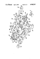
- FIG. 1 is a perspective view of the rear wheel suspension and steering system.
- FIG. 2 is an enlarged detailed view of the ball joint assembly and sleeve structure through which the wheels are mounted to the dead axle.
- FIG. 3 is a schematic plan view of the rear wheel suspension system and steering system therefor.
- FIG. 4 is a diagrammatic representation of a bus utilizing only a front steering arrangement.
- FIG. 5 is a diagrammatic representation of a bus utilizing a front and rear wheel steering system of the type permitted by the subject invention.
- FIGS. 4 and 5 are for the purpose of illustrating the improved cornering ability of a vehicle utilizing both and front and rear steerable wheels.
- a bus is indicated generally at 10 and includes steerable front wheels 12 and fixed rear driving wheels 14.
- bus 10 In driving around a corner intersection, bus 10 must first move well away from the curb of the street along which it is driving before making a right hand turn onto another street or, alternatively, the inside set of rear wheels 14 will ride over the curb.
- bus 16 utilizes steerable front wheels 18 and steerable rear wheels 20. With this latter steering arrangement, the rear end of bus 16 may be kept away from the curb by turning the rear wheels outwardly and thus enabling the bus to negotiate the right hand turn by utilizing a smaller overall turning radius.
- the basic dead axle system utilized in the present invention is of the type shown and described in U.S. Pat. No. 4,343,375 Vehicle Drive Wheel Suspension - Manning.
- the advantages of this basic type of dead axle arrangement are set forth in the aforementioned patent and are incorporated by reference herein.
- the Manning suspension has several related advantages. First, by connecting the differential drive mechanism directly to the vehicle body, the unsprung weight of the vehicle is reduced enabling the construction of a simplified and thus less costly dead axle assembly. Secondly, by not mounting the differential mechanism upon the dead axle, the overall height of the vehicle may be reduced.
- the Manning dead axle is of such construction as to permit the body supporting springs to be mounted outboard of the longitudinal centerline of the vehicle and in general alignment with the rear wheels enhance the stability of the vehicle. Both the outboard mounting of the body supporting springs and the lower vertical height permitted by the Manning suspension together contribute to a vehicle having much improved roll stability.
- a dead axle is indicated generally at 22.
- a differential drive mechanism is indicated generally at 24 and includes a power input shaft 26 and a pair of power output shafts 28 and 30.
- the power input shaft 26 is suitably connected through a universal joint, not shown, to a propeller shaft driven by an engine and transmission neither of the latter of which are shown.
- the differential output shafts 28 and 30 provide driving power to the rear wheels 20.
- the casing for differential 24 includes a pair of side bracket members and flanges 32 through which the differential is supported directly upon the vehicle body not shown.
- the differential mechanism is supported on and moves with the vehicle body and, as will be seen subsequently, such vertical or other movement may be relative to the movement or lack of movement of the dead axle 22.
- Dead axle 22 is generally of a rectilinear shape and includes a pair of longitudinal beam members 34 and 36 which extend generally parallel to the centerline of the vehicle and are disposed laterally or transversely outboard of the differential mechanism 24.
- a pair of cross beam members 38 and 40 are integrally secured to the longitudinal beams 34 and 36 and extend generally transversely of the vehicle centerline and are respectively disposed fore and aft of differential 24.
- the beams are of a light weight box construction formed by welding up relatively light weight plate members. While not similarly shown, cross beams 38,40 are of the same plate construction. It is obvious that this type of construction is substantially lighter and at least as strong as conventional dead axles utilizing a forged construction. The box construction of the individual dead axle beams greatly contributes to the reduced mass of the unsprung suspension.
- Cross beam members 38 and 40 extend transversely beyond the longitudinal beam members 34 and 36 so as to provide as wide a spring support base as possible. More specifically and in the modification shown, pads 42 are fixed to the outer most ends of the cross beams and are adapted to support suitable air bag springs not shown. As best seen in FIG. 3, the air bag support pads 42 are disposed transversely outboard of the longitudinal beams 34 and 36 and are in general alignment with the wheels 20. In this manner, maximum lateral or roll stability is provided.
- Differential input shaft 26 and dead axle cross beam member 38 are suitably vertically spaced to allow vertical movement of the differential 24 relative to the dead axle 22 without the shaft striking the cross beam.
- Radius rods 44 and 46 are suitably pivotally supported at one end through brackets 48 and 50 to longitudinal beams 34,36 and are similarly connected at their other end to the unshown vehicle body, thus, articulating the dead axle to the body in such a way that the body can move vertically relative to the dead axle.
- Longitudinal beams 34 and 36 each includes a transverse opening 52 and 54 disposed generally midway between the fore and aft ends of the beams and transversely aligned with the output shafts 28 and 30 of the differential 24.
- Rear wheel drive shafts or live axles 56 and 58 are connected at their inner ends to differential output shafts 28 and 30 through suitable universal joints 60 and 62.
- the other ends of drive shafts 56 and 58 are likewise connected through suitable universal joints 64 and 66 to wheel drive spindles 68 and 70.
- the diameters of drive shafts 56 and 58 are substantially smaller than that of the transversely aligned longitudinal beam openings 52 and 54. This arrangement allows the drive shafts 56 and 58 to move relative to the dead axle 22 without interference therewith.
- suitable slip spline connections may be provided between live axles 56 and 58 and either differential output shafts 28 and 30 or wheel spindles 68 and 70 to accommodate relative vertical movement between the differential and the dead axle.
- Sleeves 72 and 74 are respectively secured within longitudinal beam openings 52 and 54 so as to be flush with the inside of said beams and to project transversely outwardly from the outer faces of the beams.
- ball joint assemblies are indicated generally at 76 and 78. The details of the ball joint assembly will be described in relation to assembly 78 as shown in FIG. 2.
- the assembly includes a first inner support casting 80 fixed within the outer end of sleeve 74 and including outwardly projection arms 82 and 84.
- a coacting outer casting 86 rotatably supports wheel spindles 70 through a bearing member 88.
- Ball joints or other suitable bearing means 90 are disposed between outer casting 86 and inner casting arms 82 and 84 and are generally aligned through the universal joint 66 whereby the outer casing 86, spindle 70 and wheel 20 may be articulated relative to dead axle sleeve 74 to provide steerability for the rear wheels 20.
- ball joint assemblies 76 and 78 include steering arms 92 and 94 integrally formed with outer ball joint assembly casting 86.
- a power steering assembly is indicated generally at 96 and is supported upon cross beam 40 through a suitable bracket member 98.
- the power steering assembly 96 may be of any suitable type.
- power steering assembly 96 includes a pair of transversely extending rack members 100 and 102 adapted to be suitably driven by a pinion member, not shown, within the assembly.
- Rack members 100 and 102 are suitably articulated to steering rods 104 and 106.
- a second pair of aligned openings 108 and 110 are formed transversely through longitudinal beams 34 and 36.
- Steering rods 104 and 106 extend through openings 108 and 100 and are articulated at their outer ends to wheel steering arms 92 and 94.
- the power steering assembly 96 is suitable coordinated with the front wheel steering system as to permit the rear wheels to be turned either in the opposite direction from the front wheels or in the same direction as the front wheels dependent upon the type of coordinated steering movement of the vehicle desired. This steering coordinating mechanism is not a part of the subject invention.
- a disc brake assembly is indicated generally at 112.
- the assembly includes a disc 114 suitably fixed for rotation to wheel spindles 68 and 70 and a braking pad 116.
Landscapes
- Engineering & Computer Science (AREA)
- Mechanical Engineering (AREA)
- Chemical & Material Sciences (AREA)
- Combustion & Propulsion (AREA)
- Transportation (AREA)
- Vehicle Body Suspensions (AREA)
- Steering-Linkage Mechanisms And Four-Wheel Steering (AREA)
Priority Applications (4)
| Application Number | Priority Date | Filing Date | Title |
|---|---|---|---|
| US07/289,027 US4941543A (en) | 1988-12-23 | 1988-12-23 | Rear wheel suspension and steering system |
| CA002005960A CA2005960A1 (fr) | 1988-12-23 | 1989-12-19 | Systeme de suspension/direction des roues arriere |
| EP19890313393 EP0375409A3 (fr) | 1988-12-23 | 1989-12-20 | Système de suspension et de direction pour roues arrière |
| JP1336201A JPH02225114A (ja) | 1988-12-23 | 1989-12-25 | 後輪サスペンション/操縦装置 |
Applications Claiming Priority (1)
| Application Number | Priority Date | Filing Date | Title |
|---|---|---|---|
| US07/289,027 US4941543A (en) | 1988-12-23 | 1988-12-23 | Rear wheel suspension and steering system |
Publications (1)
| Publication Number | Publication Date |
|---|---|
| US4941543A true US4941543A (en) | 1990-07-17 |
Family
ID=23109704
Family Applications (1)
| Application Number | Title | Priority Date | Filing Date |
|---|---|---|---|
| US07/289,027 Expired - Fee Related US4941543A (en) | 1988-12-23 | 1988-12-23 | Rear wheel suspension and steering system |
Country Status (4)
| Country | Link |
|---|---|
| US (1) | US4941543A (fr) |
| EP (1) | EP0375409A3 (fr) |
| JP (1) | JPH02225114A (fr) |
| CA (1) | CA2005960A1 (fr) |
Cited By (5)
| Publication number | Priority date | Publication date | Assignee | Title |
|---|---|---|---|---|
| US6039143A (en) * | 1997-06-02 | 2000-03-21 | General Motors Corporation | Steerable drive axle with electrically-powered steering apparatus |
| US6202781B1 (en) * | 1997-11-28 | 2001-03-20 | Kanzaki Kokyukoki Mfg. Co., Ltd. | Power steering device for vehicles |
| US20040159995A1 (en) * | 2003-02-18 | 2004-08-19 | Pavuk Gregory D. | Sandwich design of four bag suspension for bus and coach rear drive axles |
| US20080135324A1 (en) * | 2005-01-21 | 2008-06-12 | Yanmar Co., Ltd. | Tractor |
| US20090045004A1 (en) * | 2007-08-14 | 2009-02-19 | Dana Italia S.P.A. | Steering group of the wheels of an axle of a vehicle |
Families Citing this family (2)
| Publication number | Priority date | Publication date | Assignee | Title |
|---|---|---|---|---|
| FR2891198B1 (fr) * | 2005-09-28 | 2011-02-11 | Mathieu Yno | Systeme de liaison a ressort pour vehicule etroit |
| DE602006010498D1 (de) * | 2005-09-28 | 2009-12-31 | Mathieu | Bürstenhaltevorrichtung und Reinigungsfahrzeug mit einer solchen Vorrichtung |
Citations (8)
| Publication number | Priority date | Publication date | Assignee | Title |
|---|---|---|---|---|
| US867282A (en) * | 1907-03-09 | 1907-10-01 | Wm H Donner | Steering-gear for automobiles. |
| US1850921A (en) * | 1930-02-24 | 1932-03-22 | Ghiselli Guido | Combination driving and steering axle for motor vehicles |
| US2189695A (en) * | 1938-06-18 | 1940-02-06 | Timken Axle Co Detroit | Steering-drive wheel assembly |
| US2356164A (en) * | 1940-08-03 | 1944-08-22 | Timken Axle Co Detroit | Steering wheel drive for vehicles |
| US3472331A (en) * | 1968-02-20 | 1969-10-14 | Dana Corp | Steering drive axle assembly |
| US3642084A (en) * | 1969-06-24 | 1972-02-15 | Fuji Heavy Ind Ltd | Independent front suspension system for a front wheel drive automobile |
| US3765698A (en) * | 1972-07-13 | 1973-10-16 | Gen Motors Corp | Vehicle steering system |
| US4343375A (en) * | 1979-10-22 | 1982-08-10 | Manning Donald L | Vehicle drive wheel suspension |
Family Cites Families (2)
| Publication number | Priority date | Publication date | Assignee | Title |
|---|---|---|---|---|
| GB490620A (en) * | 1937-06-02 | 1938-08-18 | Francis Dunlop Howie Ronald | Improvements relating to steering arrangements for road vehicles |
| US4355697A (en) * | 1980-09-02 | 1982-10-26 | Deere & Company | Vehicular steering and suspension system |
-
1988
- 1988-12-23 US US07/289,027 patent/US4941543A/en not_active Expired - Fee Related
-
1989
- 1989-12-19 CA CA002005960A patent/CA2005960A1/fr not_active Abandoned
- 1989-12-20 EP EP19890313393 patent/EP0375409A3/fr not_active Ceased
- 1989-12-25 JP JP1336201A patent/JPH02225114A/ja active Pending
Patent Citations (8)
| Publication number | Priority date | Publication date | Assignee | Title |
|---|---|---|---|---|
| US867282A (en) * | 1907-03-09 | 1907-10-01 | Wm H Donner | Steering-gear for automobiles. |
| US1850921A (en) * | 1930-02-24 | 1932-03-22 | Ghiselli Guido | Combination driving and steering axle for motor vehicles |
| US2189695A (en) * | 1938-06-18 | 1940-02-06 | Timken Axle Co Detroit | Steering-drive wheel assembly |
| US2356164A (en) * | 1940-08-03 | 1944-08-22 | Timken Axle Co Detroit | Steering wheel drive for vehicles |
| US3472331A (en) * | 1968-02-20 | 1969-10-14 | Dana Corp | Steering drive axle assembly |
| US3642084A (en) * | 1969-06-24 | 1972-02-15 | Fuji Heavy Ind Ltd | Independent front suspension system for a front wheel drive automobile |
| US3765698A (en) * | 1972-07-13 | 1973-10-16 | Gen Motors Corp | Vehicle steering system |
| US4343375A (en) * | 1979-10-22 | 1982-08-10 | Manning Donald L | Vehicle drive wheel suspension |
Cited By (8)
| Publication number | Priority date | Publication date | Assignee | Title |
|---|---|---|---|---|
| US6039143A (en) * | 1997-06-02 | 2000-03-21 | General Motors Corporation | Steerable drive axle with electrically-powered steering apparatus |
| US6637540B2 (en) * | 1997-06-02 | 2003-10-28 | Delphi Technologies, Inc. | Steerable drive axle with electrically-powered steering apparatus |
| US6202781B1 (en) * | 1997-11-28 | 2001-03-20 | Kanzaki Kokyukoki Mfg. Co., Ltd. | Power steering device for vehicles |
| US20040159995A1 (en) * | 2003-02-18 | 2004-08-19 | Pavuk Gregory D. | Sandwich design of four bag suspension for bus and coach rear drive axles |
| US7070177B2 (en) * | 2003-02-18 | 2006-07-04 | Arvinmeritor Technology, Llc | Sandwich design of four bag suspension for bus and coach rear drive axles |
| US20080135324A1 (en) * | 2005-01-21 | 2008-06-12 | Yanmar Co., Ltd. | Tractor |
| US7731209B2 (en) * | 2005-01-21 | 2010-06-08 | Yanmar Co., Ltd. | Tractor |
| US20090045004A1 (en) * | 2007-08-14 | 2009-02-19 | Dana Italia S.P.A. | Steering group of the wheels of an axle of a vehicle |
Also Published As
| Publication number | Publication date |
|---|---|
| JPH02225114A (ja) | 1990-09-07 |
| EP0375409A3 (fr) | 1990-09-05 |
| EP0375409A2 (fr) | 1990-06-27 |
| CA2005960A1 (fr) | 1990-06-23 |
Similar Documents
| Publication | Publication Date | Title |
|---|---|---|
| US4705128A (en) | Independent wheel suspension system having a differential pivotable about two axes | |
| US3630303A (en) | Front suspension for a front drive vehicle | |
| US5012885A (en) | Rear wheel suspension and steering system | |
| US4848789A (en) | Vehicle chassis tranverse structural member | |
| US4862987A (en) | All-wheel-drive off-highway vehicle | |
| JPS6325961B2 (fr) | ||
| SU1724007A3 (ru) | Осевой агрегат дл автомобильного прицепа | |
| US4946189A (en) | Rear suspension | |
| US3729210A (en) | Suspension system for vehicles | |
| US4817986A (en) | Vehicle body assembly used in common for two-wheel-and four-wheel-steering vehicles | |
| JPH0775928B2 (ja) | 前輪操舵装置を備えた自動車特に乗用車の後輪のための車輪懸架装置 | |
| US4941543A (en) | Rear wheel suspension and steering system | |
| US3948337A (en) | Independent front suspension for front wheel drive | |
| CA1301661C (fr) | Vehicule tout-terrain | |
| US4354567A (en) | Rear axle suspension system for motor vehicles | |
| US4585088A (en) | Articulated road vehicle with engine spaced rearwardly of driven wheels | |
| JP3750329B2 (ja) | トーションビーム式サスペンション | |
| US5054575A (en) | Dead axle suspension for a pair of driven wheels including a lateral guide | |
| JP2831347B2 (ja) | 荒地走行用車輛の前輪独立懸架装置 | |
| JPH0277310A (ja) | 前輪駆動型車両用サスペンション | |
| JPS63116912A (ja) | 駆動車輪ともなり得る操舵可能な車輪,並びにその水陸両用車両への応用 | |
| JPH0260523B2 (fr) | ||
| JPS6246575Y2 (fr) | ||
| GB2265874A (en) | Vehicle steering system. | |
| JPH0329271Y2 (fr) |
Legal Events
| Date | Code | Title | Description |
|---|---|---|---|
| AS | Assignment |
Owner name: DLMA TRANSPORTATION INC., 575 ROBBINS DRIVE, TROY, Free format text: ASSIGNMENT OF ASSIGNORS INTEREST.;ASSIGNOR:EWEN, JAMES G.;REEL/FRAME:004999/0414 Effective date: 19881028 Owner name: DLMA TRANSPORTATION INC., MICHIGAN Free format text: ASSIGNMENT OF ASSIGNORS INTEREST;ASSIGNOR:EWEN, JAMES G.;REEL/FRAME:004999/0414 Effective date: 19881028 |
|
| REMI | Maintenance fee reminder mailed | ||
| LAPS | Lapse for failure to pay maintenance fees | ||
| FP | Lapsed due to failure to pay maintenance fee |
Effective date: 19940720 |
|
| STCH | Information on status: patent discontinuation |
Free format text: PATENT EXPIRED DUE TO NONPAYMENT OF MAINTENANCE FEES UNDER 37 CFR 1.362 |