US4968123A - Helmet mounted display configured for simulator use - Google Patents
Helmet mounted display configured for simulator use Download PDFInfo
- Publication number
- US4968123A US4968123A US07/342,497 US34249789A US4968123A US 4968123 A US4968123 A US 4968123A US 34249789 A US34249789 A US 34249789A US 4968123 A US4968123 A US 4968123A
- Authority
- US
- United States
- Prior art keywords
- eyepiece
- image
- air
- observer
- optical
- Prior art date
- Legal status (The legal status is an assumption and is not a legal conclusion. Google has not performed a legal analysis and makes no representation as to the accuracy of the status listed.)
- Expired - Fee Related
Links
- 230000000007 visual effect Effects 0.000 claims abstract description 37
- 230000003287 optical effect Effects 0.000 claims description 89
- -1 ACRYL Chemical class 0.000 claims description 18
- 239000000463 material Substances 0.000 claims description 13
- 230000008878 coupling Effects 0.000 claims description 12
- 238000010168 coupling process Methods 0.000 claims description 12
- 238000005859 coupling reaction Methods 0.000 claims description 12
- 239000011521 glass Substances 0.000 claims description 8
- 238000000576 coating method Methods 0.000 claims description 5
- 239000004033 plastic Substances 0.000 claims description 5
- 229920003023 plastic Polymers 0.000 claims description 5
- 239000011248 coating agent Substances 0.000 claims description 4
- 239000000835 fiber Substances 0.000 claims description 4
- 238000011835 investigation Methods 0.000 claims description 3
- 238000002310 reflectometry Methods 0.000 claims description 3
- 239000006117 anti-reflective coating Substances 0.000 claims description 2
- 230000004044 response Effects 0.000 claims description 2
- 239000005350 fused silica glass Substances 0.000 claims 4
- 239000004417 polycarbonate Substances 0.000 claims 4
- 229920000515 polycarbonate Polymers 0.000 claims 4
- NIXOWILDQLNWCW-UHFFFAOYSA-N acrylic acid group Chemical group C(C=C)(=O)O NIXOWILDQLNWCW-UHFFFAOYSA-N 0.000 claims 3
- 230000002093 peripheral effect Effects 0.000 claims 2
- 230000003667 anti-reflective effect Effects 0.000 claims 1
- 238000009125 cardiac resynchronization therapy Methods 0.000 description 39
- VYPSYNLAJGMNEJ-UHFFFAOYSA-N Silicium dioxide Chemical compound O=[Si]=O VYPSYNLAJGMNEJ-UHFFFAOYSA-N 0.000 description 26
- 235000012239 silicon dioxide Nutrition 0.000 description 13
- 239000000377 silicon dioxide Substances 0.000 description 13
- 238000010894 electron beam technology Methods 0.000 description 8
- 230000005540 biological transmission Effects 0.000 description 6
- 238000010586 diagram Methods 0.000 description 4
- 210000001747 pupil Anatomy 0.000 description 4
- 230000004075 alteration Effects 0.000 description 3
- 238000003384 imaging method Methods 0.000 description 3
- 238000000034 method Methods 0.000 description 3
- 125000006850 spacer group Chemical group 0.000 description 3
- 238000007792 addition Methods 0.000 description 2
- XAGFODPZIPBFFR-UHFFFAOYSA-N aluminium Chemical compound [Al] XAGFODPZIPBFFR-UHFFFAOYSA-N 0.000 description 2
- 229910052782 aluminium Inorganic materials 0.000 description 2
- 208000003464 asthenopia Diseases 0.000 description 2
- 230000008901 benefit Effects 0.000 description 2
- 239000002131 composite material Substances 0.000 description 2
- 210000003128 head Anatomy 0.000 description 2
- 238000011160 research Methods 0.000 description 2
- 238000012546 transfer Methods 0.000 description 2
- 229920002972 Acrylic fiber Polymers 0.000 description 1
- 229920004943 Delrin® Polymers 0.000 description 1
- 208000003164 Diplopia Diseases 0.000 description 1
- 206010019233 Headaches Diseases 0.000 description 1
- 229920013632 Ryton Polymers 0.000 description 1
- 239000004736 Ryton® Substances 0.000 description 1
- 239000004963 Torlon Substances 0.000 description 1
- 229920003997 Torlon® Polymers 0.000 description 1
- 229920000122 acrylonitrile butadiene styrene Polymers 0.000 description 1
- 239000004676 acrylonitrile butadiene styrene Substances 0.000 description 1
- 238000013459 approach Methods 0.000 description 1
- 201000009310 astigmatism Diseases 0.000 description 1
- QVGXLLKOCUKJST-UHFFFAOYSA-N atomic oxygen Chemical compound [O] QVGXLLKOCUKJST-UHFFFAOYSA-N 0.000 description 1
- 230000008859 change Effects 0.000 description 1
- 238000013461 design Methods 0.000 description 1
- 238000011161 development Methods 0.000 description 1
- IWEDIXLBFLAXBO-UHFFFAOYSA-N dicamba Chemical compound COC1=C(Cl)C=CC(Cl)=C1C(O)=O IWEDIXLBFLAXBO-UHFFFAOYSA-N 0.000 description 1
- 208000029444 double vision Diseases 0.000 description 1
- 238000005516 engineering process Methods 0.000 description 1
- 230000001815 facial effect Effects 0.000 description 1
- 206010016256 fatigue Diseases 0.000 description 1
- 231100000869 headache Toxicity 0.000 description 1
- 229910052760 oxygen Inorganic materials 0.000 description 1
- 239000001301 oxygen Substances 0.000 description 1
- 230000005043 peripheral vision Effects 0.000 description 1
- 230000002207 retinal effect Effects 0.000 description 1
- 230000001629 suppression Effects 0.000 description 1
- 238000012360 testing method Methods 0.000 description 1
Images


Classifications
-
- G—PHYSICS
- G09—EDUCATION; CRYPTOGRAPHY; DISPLAY; ADVERTISING; SEALS
- G09B—EDUCATIONAL OR DEMONSTRATION APPLIANCES; APPLIANCES FOR TEACHING, OR COMMUNICATING WITH, THE BLIND, DEAF OR MUTE; MODELS; PLANETARIA; GLOBES; MAPS; DIAGRAMS
- G09B9/00—Simulators for teaching or training purposes
- G09B9/02—Simulators for teaching or training purposes for teaching control of vehicles or other craft
- G09B9/08—Simulators for teaching or training purposes for teaching control of vehicles or other craft for teaching control of aircraft, e.g. Link trainer
- G09B9/30—Simulation of view from aircraft
- G09B9/307—Simulation of view from aircraft by helmet-mounted projector or display
-
- A—HUMAN NECESSITIES
- A42—HEADWEAR
- A42B—HATS; HEAD COVERINGS
- A42B3/00—Helmets; Helmet covers ; Other protective head coverings
- A42B3/04—Parts, details or accessories of helmets
- A42B3/0406—Accessories for helmets
- A42B3/042—Optical devices
-
- G—PHYSICS
- G02—OPTICS
- G02B—OPTICAL ELEMENTS, SYSTEMS OR APPARATUS
- G02B13/00—Optical objectives specially designed for the purposes specified below
- G02B13/16—Optical objectives specially designed for the purposes specified below for use in conjunction with image converters or intensifiers, or for use with projectors, e.g. objectives for projection TV
-
- G—PHYSICS
- G02—OPTICS
- G02B—OPTICAL ELEMENTS, SYSTEMS OR APPARATUS
- G02B27/00—Optical systems or apparatus not provided for by any of the groups G02B1/00 - G02B26/00, G02B30/00
- G02B27/01—Head-up displays
-
- G—PHYSICS
- G02—OPTICS
- G02B—OPTICAL ELEMENTS, SYSTEMS OR APPARATUS
- G02B27/00—Optical systems or apparatus not provided for by any of the groups G02B1/00 - G02B26/00, G02B30/00
- G02B27/01—Head-up displays
- G02B27/0101—Head-up displays characterised by optical features
-
- G—PHYSICS
- G02—OPTICS
- G02B—OPTICAL ELEMENTS, SYSTEMS OR APPARATUS
- G02B27/00—Optical systems or apparatus not provided for by any of the groups G02B1/00 - G02B26/00, G02B30/00
- G02B27/01—Head-up displays
- G02B27/0149—Head-up displays characterised by mechanical features
-
- G—PHYSICS
- G02—OPTICS
- G02B—OPTICAL ELEMENTS, SYSTEMS OR APPARATUS
- G02B27/00—Optical systems or apparatus not provided for by any of the groups G02B1/00 - G02B26/00, G02B30/00
- G02B27/01—Head-up displays
- G02B27/017—Head mounted
-
- G—PHYSICS
- G02—OPTICS
- G02B—OPTICAL ELEMENTS, SYSTEMS OR APPARATUS
- G02B27/00—Optical systems or apparatus not provided for by any of the groups G02B1/00 - G02B26/00, G02B30/00
- G02B27/01—Head-up displays
- G02B27/017—Head mounted
- G02B27/0172—Head mounted characterised by optical features
-
- G—PHYSICS
- G02—OPTICS
- G02B—OPTICAL ELEMENTS, SYSTEMS OR APPARATUS
- G02B27/00—Optical systems or apparatus not provided for by any of the groups G02B1/00 - G02B26/00, G02B30/00
- G02B27/01—Head-up displays
- G02B27/017—Head mounted
- G02B27/0176—Head mounted characterised by mechanical features
-
- G—PHYSICS
- G02—OPTICS
- G02B—OPTICAL ELEMENTS, SYSTEMS OR APPARATUS
- G02B7/00—Mountings, adjusting means, or light-tight connections, for optical elements
- G02B7/02—Mountings, adjusting means, or light-tight connections, for optical elements for lenses
- G02B7/12—Adjusting pupillary distance of binocular pairs
-
- G—PHYSICS
- G02—OPTICS
- G02B—OPTICAL ELEMENTS, SYSTEMS OR APPARATUS
- G02B27/00—Optical systems or apparatus not provided for by any of the groups G02B1/00 - G02B26/00, G02B30/00
- G02B27/01—Head-up displays
- G02B27/0101—Head-up displays characterised by optical features
- G02B2027/0118—Head-up displays characterised by optical features comprising devices for improving the contrast of the display / brillance control visibility
-
- G—PHYSICS
- G02—OPTICS
- G02B—OPTICAL ELEMENTS, SYSTEMS OR APPARATUS
- G02B27/00—Optical systems or apparatus not provided for by any of the groups G02B1/00 - G02B26/00, G02B30/00
- G02B27/01—Head-up displays
- G02B27/0101—Head-up displays characterised by optical features
- G02B2027/0138—Head-up displays characterised by optical features comprising image capture systems, e.g. camera
-
- G—PHYSICS
- G02—OPTICS
- G02B—OPTICAL ELEMENTS, SYSTEMS OR APPARATUS
- G02B27/00—Optical systems or apparatus not provided for by any of the groups G02B1/00 - G02B26/00, G02B30/00
- G02B27/01—Head-up displays
- G02B27/0101—Head-up displays characterised by optical features
- G02B2027/0143—Head-up displays characterised by optical features the two eyes not being equipped with identical nor symmetrical optical devices
-
- G—PHYSICS
- G02—OPTICS
- G02B—OPTICAL ELEMENTS, SYSTEMS OR APPARATUS
- G02B27/00—Optical systems or apparatus not provided for by any of the groups G02B1/00 - G02B26/00, G02B30/00
- G02B27/01—Head-up displays
- G02B27/0149—Head-up displays characterised by mechanical features
- G02B2027/0154—Head-up displays characterised by mechanical features with movable elements
- G02B2027/0159—Head-up displays characterised by mechanical features with movable elements with mechanical means other than scaning means for positioning the whole image
-
- G—PHYSICS
- G02—OPTICS
- G02B—OPTICAL ELEMENTS, SYSTEMS OR APPARATUS
- G02B27/00—Optical systems or apparatus not provided for by any of the groups G02B1/00 - G02B26/00, G02B30/00
- G02B27/01—Head-up displays
- G02B27/0179—Display position adjusting means not related to the information to be displayed
- G02B2027/0187—Display position adjusting means not related to the information to be displayed slaved to motion of at least a part of the body of the user, e.g. head, eye
Definitions
- This invention relates to helmet mounted displays, and more particularly to a helmet mounted display configured for simulator use.
- Helmet mounted displays are used in aircraft and rotorcraft to aid a pilot in visually interpreting data
- computer generated flight data is fed to a CRT image source, whose image is projected optically into the pilot's forward visual field of view (FOV)
- FOV forward visual field of view
- the HMD thus allows the pilot to spend more time piloting the craft in a head-up mode, i e., looking out at the exterior scene and not looking down as often at the instrument panel.
- partial overlap imaging systems may pose problems such as retinal rivalry wherein left and right images are alternately perceived Also, since each eye views a different image, image suppression can occur wherein only one dominant image is perceived. Associated problems include eyestrain, headaches, and fatigue from the observer's effort to fuse misaligned images. Also, since the CRT image sources typically have limited resolution, the larger the desired FOV, the less the resolution. Some of these problems relate to image alignment in the overlap region; some relate to the amount of partial overlap. Thus, a need exists for a HMD which permits the investigation of various combinations of FOV, FOV overlap, and resolution in order to evaluate observer performance and determine optimum partial overlap configurations.
- Objects of the invention include providing a partial overlap HMD having binocular optic means and optical and mechanical means for varying the degree of partial overlap of the left and right visual fields. Further objects include providing an HMD with interchangeable catadioptric and refractive eyepieces, and providing the HMD with coupled external viewing optics.
- helmet mounted apparatus includes an image source and an independent optical arrangement for each eye, each arrangement having day/night relay optics disposed along the image source optical axis, and having a rotatable eyepiece, said eyepiece being releasably engageable from the relay optics to permit use of different eyepiece embodiments for daytime and nighttime light conditions, the relay optics presenting the source image along the optical path to the engaged eyepiece into the observer's forward visual field, whereby the rotation of the eyepiece varies the amount of overlap of the left and right eye images presented in the observer's forward visual field.
- a viewing objective lens and refractive means are releasably engaged to the day/night relay optics by means of a rotatable coupling, the objective lens disposed on the helmet to view the external scene forward of the observer, the refractive means disposed to couple the external scene image on the objective lens into the optical path of the relay optics, the relay optics presenting both the image source image and the external scene image to the engaged nighttime embodiment eyepiece into the observer's forward visual field.
- the present invention allows the observer to rotate the eyepiece about a vertical axis through the center of each eyepiece, thereby presenting different fields of view to each eye. This varies the total binocular FOV with respect to total horizontal FOV and binocular overlap. With no eyepiece rotation, both images are entirely overlapped; thus, the total binocular FOV is at its smallest value. With eyepiece rotation, the left eye is presented with a portion of the image from the left eye image source, the right eye is presented with a portion of the image from the right eye image source, and portions of each image overlap, the overlap portion being seen by both eyes. If the rotation is at its extreme value, then zero overlap exists.
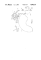
- FIG. 1 is a top view of HMD simulator apparatus in accordance with the present invention.
- FIG. 2 is a side view of the HMD simulator apparatus of FIG. 1;
- FIG. 3 is a front view of the HMD simulator apparatus of FIG. 1;
- FIG. 4 is a partial cross section of one optical arrangement used in the HMD apparatus of FIG. 1;
- FIG. 5 is an optical ray trace of an embodiment of optical components as may be used in the arrangement of FIG. 4;
- FIG. 6 is an optical ray trace of an alternate embodiment of one portion of the optical arrangement of FIG. 4;
- FIG. 7 is a second front view of the HMD simulator apparatus of FIG. 1, but with an eyepiece disengaged;
- FIG. 8 is a functional block diagram of the HMD simulator apparatus of FIG. 1 together with associated support components;
- FIG. 9 is a block diagram of video drive electronics as used in FIG. 8;
- FIG. 10 is an optical ray trace of an alternative embodiment to the arrangement of FIG. 4.
- FIG. 11 is a second side view of the HMD simulator apparatus of FIG. 1, but including the alternative embodiment of FIG. 10.
- FIGS. 1-3 illustrate top, side, and front views, respectively, of HMD simulator apparatus 10 in accordance with the present invention.
- the HMD 10 mounts to an outer surface of a known type aviator's helmet 12, e.g., Model HGU55 from Gentex Corp. of California.
- the helmet outer surface provides an opening in proximity to the facial area of an observer wearing the helmet 12.
- the HMD comprises two CRT image sources 14,15, each with an identical, independent, modular optics arrangement 17,18 for each eye.
- Each arrangement 17,18 comprises an aluminum or suitable plastic or composite material housing 21,22 enclosing relay optics (not visible) common to both day and night luminance conditions.
- Each arrangement also comprises an interchangeable, rotatable day eyepiece 24 and an interchangeable, rotatable night eyepiece 25.
- the eyepieces shown in FIGS. 1-3 are illustrative of either the day or night eyepiece.
- Each eyepiece 24,25 comprises an aluminum or suitable plastic (e.g., Delrin, ABS, Ryton, Torlon) or composite material housing 27,28 enclosing optical components (not visible), with different embodiments for day or night light conditions. Either the day or night eyepiece is engaged to the relay optics at one time. Further HMD features illustrated in FIGS. 1-3 are described hereinafter.
- FIG. 4 is a cross-section view of one of two identical arrangements 17,18 (e.g., the left eye arrangement 17).
- the image source 14 is typically a one inch diameter, miniature CRT, e.g., Model H-1380 from Hughes Aircraft Company, Industrial Products Division, Carlsbad, Calif.
- the CRT presents a visual image on a fiber optic faceplate 30, and attaches to the relay optics housing 21 by a flange 32 glued to the CRT and a threaded nut assembly 34. Proceeding along an optical axis 36, a pair of glass lenses 38,39 follow the faceplate 30.
- the first lens 38 is positioned with a machined seat 42 while the second lens 39 rests against the first lens 38.
- a first tubular spacer 44 follows the second lens 39, followed by a third lens 46, a second tubular spacer 48, and a second pair of lenses 50,51.
- a retaining nut 54 holds the lenses 38,39,46,50,51 and spacers 44,48 in place.
- the lens pair lenses 38,39,50,51 comprise different types of glass (e.g., F4 and silicon dioxide (SIO2)) so as to reduce chromatic abberrations.
- a first split line 56 designates a physical break in the relay optics housing 21; a first part 58 following the CRT 14 is either press-fitted or glued into a second part 59 disposed along the image source optical axis 36 following the first part 58.
- a fold mirror 62 is used to direct the optical image rays downward into the second part 59 of the relay optics housing 21.
- the fold mirror 62 attaches to the relay optics housing using well known, low stress optical component mounting techniques.
- the relay optics housing 21 ends at a second split line 64, below which is the eyepiece housing 27.
- the eyepiece 24 is catadioptric and employs a partially transmissive, partially reflective combiner 66 and beamsplitter 68 optical components. All eyepiece components (both for the day and night eyepieces) are held in place in machined seats 70,71 (the night eyepiece components are illustrated in FIG. 6).
- FIG. 5 illustrates an optical ray trace of one of the identical arrangements 17,18, including the relay optics 21 and day eyepiece 24.
- the CRT image faceplate 30 has a surface 84 of 40 mm radius.
- the image rays travel through air a distance of 62.6 mm to a first surface 85 of the first glass lens 38. All distances listed in Table I are measured from the component centers.
- the first surface 85 of the first lens 38 is convex with a radius of 28.285 mm, a 3.0 mm thickness, and comprises F4 glass. The remaining components are determined from FIG. 5 and Table I in a similar manner.
- a surface 95 of the fold mirror 62 comprises an aluminized reflective coating
- a surface 100 of the beamsplitter 68 is listed twice in Table I because it reflects the image rays to mirror surface 101 (a distance of 34.801353 mm), which reflects the rays back to and through the beamsplitter 68, whose thickness is 3 mm.
- Surface 103 is that of the image exit pupil, approximately 8 mm in diameter.
- the relay optics forms an intermediate focused image of the image of the CRT at a focal plane which is at a distance of approximately 215 mm along the optical axis 36 from the faceplate 30.
- the useful range of the intermediate image focal plane can range up to 400 mm; thus, the location of the intermediate image focal plane may be approximated by the location of the second split line 64.
- the focused image at the intermediate image focal plane is at a magnification of 2.0 times the image of the CRT.
- the useful range of the magnification can range from 0.5-4.0.
- the day eyepiece 24 presents a virtual image of the CRT in the observer's forward visual FOV.
- the virtual image is focused at a distance of from one meter to infinity from the observer's eye.
- the day eyepiece components are designed for approximately 36% see-through light transmission from the external scene disposed beyond the eyepiece.
- the virtual image is superposed on the observer's view of the external scene.
- the virtual image occupies a portion of the observer's visual field having a minimum subtense at the eye of 10 degrees.
- the active image area of the miniature CRT 14,15 is 19 mm in diameter.
- the diameters of the relay optics lenses 38,39,46,50,51 are chosen to contain the rays therein.
- the relay optics lenses are all glass; either F4 or SIO2, while the eyepiece components 66,68 are all acrylic plastic. Plastic was chosen for weight and safety reasons. However, it is to be understood that the eyepiece components can be glass without detracting from the scope of the present invention.
- All components other than the fold mirror 62 have a known antireflective coating.
- the coatings on the combiner surface 101 and beamsplitter surface 100 are adjusted for a partial reflectivity of 20%-60% of visible light in the wavelength range of 400-700 nanometers.
- the type and radius of curvatures of all components are chosen in part to control astigmatism and spherical aberrations.
- Each component in FIG. 5 can be built from the Table I data using known techniques.
- FIG. 6 illustrates an optical ray trace of the night eyepiece 25 for use with the relay optics 21 of FIG. 4; the ray trace of the relay optics is the same as in FIG. 5.
- Table II lists the corresponding prescription data for the relay optics and night eyepiece.
- the refractive night eyepiece includes lenses 105, 106,107 and a mirror 109.
- Mirror surface 114 is an opaque, aluminized surface which totally reflects the CRT image rays into the observer's forward visual field, and also blocks transmission of the external scene into the observer's visual field.
- the image presented to the observer's forward visual field occupies an angle with a minimum subtense at the eye of 20 degrees.
- the optical component arrangements 17,18 are each located in a vertical plane through an eye of the observer. This vertical orientation facilitates the presentation of the partial overlap image to the eyes, upon rotation of the eyepieces.
- an alternative arrangement may be used if mechanized to allow outward image rotation of the eyepiece optic axes relative to the downward line of sight.
- Each eyepiece housing 27,28 engages the corresponding relay optics housing 21,22 by releasable, rotatable coupling means 130,131.
- FIG. 7 there illustrated is a front view of the HMD simulator apparatus 10 with the right eyepiece housing 28 disengaged from the relay optics housing 22 (as illustrated by dashed lines 134).
- a grooved portion 136 of the eyepiece housing 28 slides into a grooved portion 138 of the relay optics housing 22 from the front of the helmet 12. This allows the observer to readily change the eyepieces 24,25.
- the grooved portions 136,138 of the eyepiece and relay optics housings 28,22 also allow eyepiece rotation when engaged.
- the HMD simulator of the present invention allows for manual rotation of each eyepiece independently, about an axis 142 through the second part 59 (ref. FIG. 4 also) of the relay optics housing 21,22 and through the center of the eyepiece housing 27,28 (as illustrated in FIG. 1 and by the rotational arrowheads 144 in FIG. 2).
- rotating an eyepiece through an angle about this vertical axis 142 causes the image to rotate through an equal angle.
- the observer must compensate by derotating the image source image by physical rotation of the CRTs, or by electronic rotation of the CRT image by the CRT drive electronics.
- Methods of electronic rotation of images are well-known, as illustrated by U.S. Pat. Nos. 3,959,582 and 3,641,260.
- the rotation allows the day eyepiece FOV to range from 31 degrees (100% overlap of the left and right images at 0 degrees rotation) to 31 vertical degrees ⁇ 62 horizontal degrees (0% overlap with each eyepiece rotated outward by 15.5 degrees).
- Rotation of the night eyepiece allows the FOV to increase from 40 degrees (100% overlap) to 40 ⁇ 80 degrees (0% overlap with each eyepiece rotated outward by 20 degrees).
- the relay optics housings 21,22 connect together by a first slidable rod 150 on the crown of the helmet 12, and by a second slidable rod 152 on the front of the helmet.
- the rods 150,152 slide within housings 154,155,156,157 attached to each relay optics housing, and also within housings 158,159 attached to a mounting bracket 162.
- the rods slide in response to a threaded thumbscrew adjustable rod 164.
- Female threaded housings 166,167 attach to each relay optics housing.
- the thumbscrew rod 164 mates with the threaded housings 166,167, and a thumbscrew 170 on the front of the helmet facilitates the adjustment.
- the thumbscrew rod adjusts the interpupillary distance (IPD) between the optical arrangements 17,18.
- the HMD 10 allows for an IPD adjustment range of 58.9-73.3 mm, which is suitable for a wide range of observer head sizes.
- the IPD adjustment is also necessary because, when an eyepiece is rotated, the eyepiece exit pupil no longer aligns with the observer's line of sight. Thus, the optical axis in the eyepiece must be translated to align the exit pupil with the observer's line of sight.
- a second thumbscrew 174 adjusts the vertical positioning of the optical component arrangements 17,18.
- the second thumbscrew 174 is part of a threaded rod 176 which threads into the front portion of the helmet 12.
- the threaded rod passes through a slot 178 in the front mounting bracket 162.
- FIG. 8 illustrates a block diagram of the HMD together with associated lab components.
- the components include video drive electronics 186 for control of the CRTs 14,15, and a computer 188 or other known, suitable device for generating both electronic image data and video drive electronics control signals.
- the video drive electronics 186 are of a known type and are not a part of the present invention. Any suitable circuitry for controlling a CRT may be used.
- a pair of video cameras (not shown) may be used for scanning a simulated scenic image.
- the computer For use with the catadioptric (day) eyepiece 24, the computer generates symbol image data, which includes typical flight data related to pilotage (e.g., weapon aiming or targetry data). For use with the refractive (night) eyepiece 25, and the computer either generates image data of a simulated scene superposed with symbol data, or the simulated scene data itself.
- the computer 188 feeds the signal information on signal lines 190 to the drive electronics 186 using, e.g., the RS-343 or RS-170 video data transmission protocols.
- the drive electronics connect to each CRT 14,15 by shielded cables 192,193.
- the video drive electronics 186 operate the CRT in either the stroke (symbol) mode or the raster (scenic image) mode.
- FIG. 9 is a functional block diagram of the drive electronics for a single CRT.
- the CRT electron beam writes information in a line by line scanning sequence.
- the computer generated signals on the lines 190 include both synchronization signals for the CRT deflection circuitry and CRT beam intensity signals.
- stroke mode the CRT electron beam writes the information on the CRT screen by proper positioning of the horizontal and vertical deflection signals, while keeping the electron beam intensity constant.
- the signals on the lines 192 to the CRT include beam deflection and blanking signals.
- the drive electronics operate the CRT simultaneously in stroke and raster modes. After the electron beam completes one field in raster mode, the electron beam enters the stroke mode and writes the symbol data on the screen. The beam then retraces vertically and begins raster scanning again.
- the computer signals are fed on a line 198 to a video amplifier 200.
- the amplified signal output on a line 202 is fed to a sync separator 204 and also on the lines 192 to the CRT.
- the sync separator 204 removes the horizontal and vertical timing signal content and feeds the resulting horizontal and vertical sync signals on signal lines 210,211, respectively, to horizontal and vertical sweep generators 213,214.
- the sweep signal outputs are fed on lines 216,217 to the CRT to control the scanning sequence.
- the video amplifier output signal on the line 202 controls the intensity of the electron beam.
- the computer generated signal information on the lines 190 includes horizontal and vertical deflection signals, and electron beam blanking signals
- the deflection signals on lines 220,221 are fed to horizontal and vertical deflection amplifiers 224,225, whose outputs on lines 227,228 are fed on the lines 192 to the CRT.
- the deflection signals position the symbols on the CRT screen.
- the blanking signal on a line 230 is fed to a cathode driver amplifier 232, whose output on a line 233 is fed to the CRT.
- the blanking signal turns the electron beam on and off.
- the day eyepiece 24 provides a 31 degree monocular FOV with approximately 36% see-through luminance transmission, and approximately 6% luminance transfer from the CRT (60% beamsplitter transmission, 60% combiner transmission).
- the night eyepiece provides for a 40 degree monocular FOV, and nearly 100% luminance transfer from the CRT with no see-through.
- the eyepieces are designed for very different viewing conditions: high luminance symbols superposed on the external scene, and low luminance, high resoultion imagery.
- Each optical component arrangement 17,18 accomodates a CRT image source 14,15 having an active image diameter in the useful range of 16-25 mm (actual diameter is 19 mm). Also, each arrangement 17,18, including the eyepiece 24,25, has an effective focal length in the range of 15-55 mm (actual is 36 mm with the day eyepiece; 37 mm with the night eyepiece). Each eyepiece has a minimum 8 mm exit pupil, and an eye relief of 24 mm (eye relief being the distance from the eye to the nearest optical component). This eye relief allows for excellent observer peripheral vision and the wearing of eyeglasses and/or an oxygen mask.
- FIG. 10 illustrates an alternative embodiment of the optical component arrangement illustrated in FIG. 5.
- Table III lists the corresponding prescription data.
- the alternative embodiment includes the relay optics of FIG. 5 and the night eyepiece of FIG. 6, with the addition of a known viewing objective lens 250 and refractive means 252 -260 for coupling an image of the external scene into the observer's forward visual field.
- the viewing objective lens 250 forms an image of an external scene on an input face 252 of a known fiber optic inverter 254.
- This inverter 254 provides an image at an output surface 256 which is rotated by 180 degrees.
- the curvature of the output image surface 256 of the fiber optic inverter is optically designed to present a flat field.
- a reflecting prism 258 and beamsplitter 260 are used to direct rays into the relay optics 21.
- the virtual image presented in the observer's forward visual field is a superposition of the CRT symbol data and the external scene.
- the viewing objective lens 250 is selected to have the same FOV as the monocular virtual image presented into the observer's visual field (e.g., 40 degrees for use with the night eyepiece).
- the viewing objectives lenses one for each optical component arrangement 17,18
- the eyepiece housings 27,28 are correspondingly rotated to present a partial overlap image.
- surfaces 300,301 are that of beamsplitter 260, while surfaces 302,303,304 are surfaces of prism 258.
- the viewing objective lens 250, inverter 254, and prism 258 are helmet mounted on a rotatable coupling 310 that allows for rotation of the devices 250,254,258 about a vertical axis 312.
- the viewing objective lens is disposed to view an external scene.
- the beamsplitter 260 mounted internal to the relay optics housing 21,22.
- the devices 250,254,258 can be mounted in a suitable housing (not shown) that attaches to the rotatable coupling 310, or they can be secured together in a suitable manner. In this case, the CRTs are generating symbol data images.
- Binocular imaging with partial overlap of the left and right visual fields places strict requirements on the viewing optics, since superposition of image elements in the overlap region is extremely critical if visual problems such as double vision or eyestrain are to be avoided. Thresholds for misalignment leading to visual problems as low as one milliradian in the visual field can exist. Also, optical disparities between the left and right channels due to magnification differences, curvature of field, and distortion must be controlled. For example, curvature of field is an optical aberration whereby the focus position varies over the FOV.
- FIGS. 5,6,10 and Tables I-III set forth an optical design with aberration control compatible with partial overlap imaging.
- the HMD of the present invention provides the researcher with an ability to test a wide variety of optical configurations, including continuously variable fields of view, see-through or no see through, full overlap, or no overlap, and binocular or monocular viewing, all over a wide range of interpupillary distances.
- it is an ideal tool for evaluating HMD technology in regard to human factors research and display format development.
Landscapes
- Physics & Mathematics (AREA)
- General Physics & Mathematics (AREA)
- Optics & Photonics (AREA)
- Engineering & Computer Science (AREA)
- Theoretical Computer Science (AREA)
- Aviation & Aerospace Engineering (AREA)
- Business, Economics & Management (AREA)
- Educational Administration (AREA)
- Educational Technology (AREA)
- Lenses (AREA)
Priority Applications (6)
| Application Number | Priority Date | Filing Date | Title |
|---|---|---|---|
| US07/342,497 US4968123A (en) | 1989-04-24 | 1989-04-24 | Helmet mounted display configured for simulator use |
| EP19900630091 EP0395570A3 (en) | 1989-04-24 | 1990-04-19 | Helmet mounted display configured for simulator use |
| DE199090630091T DE395570T1 (de) | 1989-04-24 | 1990-04-19 | Auf einem helm montiertes anzeigegeraet, angeordnet fuer simulatorgebrauch. |
| IL94161A IL94161A0 (en) | 1989-04-24 | 1990-04-22 | Helmet mounted display configured for simulator use |
| CA002015166A CA2015166A1 (en) | 1989-04-24 | 1990-04-23 | Helmet mounted display configured for simulator use |
| JP2108552A JPH03110593A (ja) | 1989-04-24 | 1990-04-24 | フライトシミュレータ用観測者頭部搭載のデイスプレイ装置 |
Applications Claiming Priority (1)
| Application Number | Priority Date | Filing Date | Title |
|---|---|---|---|
| US07/342,497 US4968123A (en) | 1989-04-24 | 1989-04-24 | Helmet mounted display configured for simulator use |
Publications (1)
| Publication Number | Publication Date |
|---|---|
| US4968123A true US4968123A (en) | 1990-11-06 |
Family
ID=23342089
Family Applications (1)
| Application Number | Title | Priority Date | Filing Date |
|---|---|---|---|
| US07/342,497 Expired - Fee Related US4968123A (en) | 1989-04-24 | 1989-04-24 | Helmet mounted display configured for simulator use |
Country Status (6)
| Country | Link |
|---|---|
| US (1) | US4968123A (ja) |
| EP (1) | EP0395570A3 (ja) |
| JP (1) | JPH03110593A (ja) |
| CA (1) | CA2015166A1 (ja) |
| DE (1) | DE395570T1 (ja) |
| IL (1) | IL94161A0 (ja) |
Cited By (30)
| Publication number | Priority date | Publication date | Assignee | Title |
|---|---|---|---|---|
| US5331459A (en) * | 1991-12-10 | 1994-07-19 | Litton Systems, Inc. | Night vision system and mounting assembly |
| US5347400A (en) * | 1993-05-06 | 1994-09-13 | Ken Hunter | Optical system for virtual reality helmet |
| US5357372A (en) * | 1992-04-07 | 1994-10-18 | Hughes Aircraft Company | Ultra-compact, wide field of view virtual image display optical system |
| US5384654A (en) * | 1993-05-10 | 1995-01-24 | Olympus Optical Co., Ltd. | Image observation device |
| US5406415A (en) * | 1992-09-22 | 1995-04-11 | Kelly; Shawn L. | Imaging system for a head-mounted display |
| US5479224A (en) * | 1992-12-25 | 1995-12-26 | Olympus Optical Co., Ltd. | Image display apparatus |
| US5488508A (en) * | 1994-06-28 | 1996-01-30 | The Walt Disney Company | Vignetting technique for improving appearance of partially overlapped binocular displays |
| US5526022A (en) | 1993-01-06 | 1996-06-11 | Virtual I/O, Inc. | Sourceless orientation sensor |
| US5579165A (en) * | 1991-10-31 | 1996-11-26 | Thomson-Csf | Computerized binoculars |
| US5581271A (en) * | 1994-12-05 | 1996-12-03 | Hughes Aircraft Company | Head mounted visual display |
| US5587836A (en) * | 1993-05-13 | 1996-12-24 | Olympus Optical Co., Ltd. | Visual display apparatus |
| US5619377A (en) * | 1992-02-07 | 1997-04-08 | Virtual I/O, Inc. | Optically corrected helmet mounted display |
| US5734359A (en) * | 1994-07-01 | 1998-03-31 | B.V. Optische Industrie "De Oude Delft" | Display system intended to be attached to the head or to a helmet, and a helmet provided with such a display system |
| US5757546A (en) * | 1993-12-03 | 1998-05-26 | Stereographics Corporation | Electronic stereoscopic viewer |
| US5786932A (en) * | 1993-12-19 | 1998-07-28 | International Technologies (Lasers), Ltd. | Vision assisting apparatus |
| US5864326A (en) * | 1992-02-07 | 1999-01-26 | I-O Display Systems Llc | Depixelated visual display |
| US5903395A (en) * | 1994-08-31 | 1999-05-11 | I-O Display Systems Llc | Personal visual display system |
| US5903396A (en) * | 1997-10-17 | 1999-05-11 | I/O Display Systems, Llc | Intensified visual display |
| US5923477A (en) * | 1994-02-07 | 1999-07-13 | Olympus Optical Co., Ltd. | Image display apparatus having a reflecting surface that bends light rays |
| US5991087A (en) * | 1993-11-12 | 1999-11-23 | I-O Display System Llc | Non-orthogonal plate in a virtual reality or heads up display |
| US5991085A (en) | 1995-04-21 | 1999-11-23 | I-O Display Systems Llc | Head-mounted personal visual display apparatus with image generator and holder |
| US6094182A (en) * | 1993-03-03 | 2000-07-25 | Maguire, Jr.; Francis J. | Apparatus and method for providing images for viewing at various distances |
| US6097543A (en) * | 1992-02-07 | 2000-08-01 | I-O Display Systems Llc | Personal visual display |
| US6160666A (en) * | 1994-02-07 | 2000-12-12 | I-O Display Systems Llc | Personal visual display system |
| US6330121B1 (en) * | 1997-11-17 | 2001-12-11 | Olympus Optical Co., Ltd. | Optical prism, display element support and optical assembly using the same |
| US7190392B1 (en) * | 1997-10-23 | 2007-03-13 | Maguire Jr Francis J | Telepresence system and active/passive mode display for use therein |
| US8284506B2 (en) | 2008-10-21 | 2012-10-09 | Gentex Corporation | Apparatus and method for making and assembling a multi-lens optical device |
| US8355208B1 (en) | 2010-06-15 | 2013-01-15 | Rockwell Collins, Inc. | Quick adjustment mechanism for head or helmet mounted displays |
| US20140085607A1 (en) * | 2012-09-24 | 2014-03-27 | Altek Corporation | Image detecting apparatus and image detecting method |
| US10409068B1 (en) * | 2018-03-27 | 2019-09-10 | Tectus Corporation | Binocular femtoprojector layouts |
Families Citing this family (17)
| Publication number | Priority date | Publication date | Assignee | Title |
|---|---|---|---|---|
| FR2708428B1 (fr) * | 1992-12-22 | 1995-09-01 | Sextant Avionique | Casque de protection équipé de systèmes optroniques et procédé de réglage. |
| DE69433821T2 (de) * | 1993-08-20 | 2005-06-16 | Seiko Epson Corp. | Am Kopf montierte Bildanzeigevorrichtung |
| US6538624B1 (en) | 1993-08-20 | 2003-03-25 | Seiko Epson Corporation | Head-mounted image display apparatus |
| EP0716329B1 (en) * | 1994-06-23 | 2003-08-27 | Seiko Epson Corporation | Head-mounted display device |
| GB2295026A (en) * | 1994-11-09 | 1996-05-15 | Michael Harold Freeman | Off axis projection optics for head mounted display |
| FR2742636B1 (fr) * | 1995-12-26 | 1998-02-06 | Sextant Avionique | Casque a dispositif de vision nocturne a securite et ergonomie optimisees |
| US6011653A (en) * | 1996-03-11 | 2000-01-04 | Seiko Epson Corporation | Head-mounted display |
| GB9726413D0 (en) * | 1997-12-15 | 1998-02-11 | Retinal Display Cayman Limited | Display apparatus |
| KR100612585B1 (ko) * | 1998-07-04 | 2007-04-25 | 엘지전자 주식회사 | 집중각조정장치를가지는헤드마운트디스플레이 |
| US6522474B2 (en) * | 2001-06-11 | 2003-02-18 | Eastman Kodak Company | Head-mounted optical apparatus for stereoscopic display |
| FR2834799B1 (fr) * | 2002-01-11 | 2004-04-16 | Essilor Int | Lentille ophtalmique presentant un insert de projection |
| US8120857B2 (en) | 2008-10-15 | 2012-02-21 | Gentex Corporation | Apparatus and method for mounting and calibrating a helmet-mounted display |
| EP2583131B1 (en) * | 2010-06-15 | 2019-11-06 | Razer (Asia Pacific) Pte. Ltd. | Personal viewing devices |
| WO2017127494A1 (en) | 2016-01-22 | 2017-07-27 | Corning Incorporated | Wide field personal display |
| US10976551B2 (en) | 2017-08-30 | 2021-04-13 | Corning Incorporated | Wide field personal display device |
| CN111044258B (zh) * | 2019-11-28 | 2021-09-28 | 扬州莱达光电技术有限公司 | 一种头盔显示器盔内仿真测试装置 |
| CN113038114B (zh) * | 2021-02-01 | 2022-08-16 | 中国船舶重工集团公司第七0九研究所 | 基于人眼视觉特性的ar仿真系统及方法 |
Citations (16)
| Publication number | Priority date | Publication date | Assignee | Title |
|---|---|---|---|---|
| US3059519A (en) * | 1956-09-05 | 1962-10-23 | Austin N Stanton | Headgear mounted cathode ray tube and binocular viewing device |
| US3614314A (en) * | 1967-03-21 | 1971-10-19 | Bendix Corp | Optical display means for an all-weather landing system of an aircraft |
| USRE27356E (en) * | 1970-08-17 | 1972-05-09 | Infinite optical image-forming apparatus | |
| US3870405A (en) * | 1973-06-12 | 1975-03-11 | Honeywell Inc | Helmet sight visors |
| US3923370A (en) * | 1974-10-15 | 1975-12-02 | Honeywell Inc | Head mounted displays |
| US4028725A (en) * | 1976-04-21 | 1977-06-07 | Grumman Aerospace Corporation | High-resolution vision system |
| US4153913A (en) * | 1976-06-18 | 1979-05-08 | Pilkington P.E. Limited | Head-up displays |
| US4218111A (en) * | 1978-07-10 | 1980-08-19 | Hughes Aircraft Company | Holographic head-up displays |
| US4225215A (en) * | 1977-05-03 | 1980-09-30 | Thomson-Csf | Display instrument using optical collimation |
| US4508424A (en) * | 1981-05-08 | 1985-04-02 | Ruder Nils I A | Binocular display of information with two combiner means |
| US4660943A (en) * | 1984-12-17 | 1987-04-28 | Gec Avionics Limited | Night vision systems |
| US4669810A (en) * | 1984-02-03 | 1987-06-02 | Flight Dynamics, Inc. | Head up display system |
| US4755664A (en) * | 1985-07-31 | 1988-07-05 | Gec Avionics Limited | Night vision systems |
| US4761056A (en) * | 1987-03-27 | 1988-08-02 | Kaiser Aerospace And Electronics Corporation | Compact helmet mounted display |
| US4763990A (en) * | 1984-02-03 | 1988-08-16 | Flight Dynamics, Inc. | Head up display system |
| US4775217A (en) * | 1981-10-14 | 1988-10-04 | Gec Avionics Limited | Night vision viewing system |
Family Cites Families (5)
| Publication number | Priority date | Publication date | Assignee | Title |
|---|---|---|---|---|
| DE2212306C3 (de) * | 1972-03-14 | 1974-09-19 | Anschuetz & Co Gmbh, 2300 Kiel | Rundblickperiskop für Fahrzeuge |
| US4323298A (en) * | 1978-12-07 | 1982-04-06 | Baird Corporation | Wide field of view goggle system |
| EP0252200A1 (en) * | 1986-07-08 | 1988-01-13 | OIP OPTICS Naamloze Vennootschap | Night vision goggles |
| US4915487A (en) * | 1989-02-01 | 1990-04-10 | Systems Research Laboratories | Heads up display for night vision goggle |
| US4961626A (en) * | 1989-02-21 | 1990-10-09 | United Techologies Corporation | Direct incorporation of night vision in a helmet mounted display |
-
1989
- 1989-04-24 US US07/342,497 patent/US4968123A/en not_active Expired - Fee Related
-
1990
- 1990-04-19 EP EP19900630091 patent/EP0395570A3/en not_active Withdrawn
- 1990-04-19 DE DE199090630091T patent/DE395570T1/de active Pending
- 1990-04-22 IL IL94161A patent/IL94161A0/xx unknown
- 1990-04-23 CA CA002015166A patent/CA2015166A1/en not_active Abandoned
- 1990-04-24 JP JP2108552A patent/JPH03110593A/ja active Pending
Patent Citations (16)
| Publication number | Priority date | Publication date | Assignee | Title |
|---|---|---|---|---|
| US3059519A (en) * | 1956-09-05 | 1962-10-23 | Austin N Stanton | Headgear mounted cathode ray tube and binocular viewing device |
| US3614314A (en) * | 1967-03-21 | 1971-10-19 | Bendix Corp | Optical display means for an all-weather landing system of an aircraft |
| USRE27356E (en) * | 1970-08-17 | 1972-05-09 | Infinite optical image-forming apparatus | |
| US3870405A (en) * | 1973-06-12 | 1975-03-11 | Honeywell Inc | Helmet sight visors |
| US3923370A (en) * | 1974-10-15 | 1975-12-02 | Honeywell Inc | Head mounted displays |
| US4028725A (en) * | 1976-04-21 | 1977-06-07 | Grumman Aerospace Corporation | High-resolution vision system |
| US4153913A (en) * | 1976-06-18 | 1979-05-08 | Pilkington P.E. Limited | Head-up displays |
| US4225215A (en) * | 1977-05-03 | 1980-09-30 | Thomson-Csf | Display instrument using optical collimation |
| US4218111A (en) * | 1978-07-10 | 1980-08-19 | Hughes Aircraft Company | Holographic head-up displays |
| US4508424A (en) * | 1981-05-08 | 1985-04-02 | Ruder Nils I A | Binocular display of information with two combiner means |
| US4775217A (en) * | 1981-10-14 | 1988-10-04 | Gec Avionics Limited | Night vision viewing system |
| US4669810A (en) * | 1984-02-03 | 1987-06-02 | Flight Dynamics, Inc. | Head up display system |
| US4763990A (en) * | 1984-02-03 | 1988-08-16 | Flight Dynamics, Inc. | Head up display system |
| US4660943A (en) * | 1984-12-17 | 1987-04-28 | Gec Avionics Limited | Night vision systems |
| US4755664A (en) * | 1985-07-31 | 1988-07-05 | Gec Avionics Limited | Night vision systems |
| US4761056A (en) * | 1987-03-27 | 1988-08-02 | Kaiser Aerospace And Electronics Corporation | Compact helmet mounted display |
Non-Patent Citations (6)
| Title |
|---|
| E. Lewis and B. Amos, A High Resolution Vision System for Aircraft and Trainers, NAECON 76 Record, pp. 894 902. * |
| E. Lewis and B. Amos, A High Resolution Vision System for Aircraft and Trainers, NAECON'76 Record, pp. 894-902. |
| Martin Shenker, Optical Design Criteria for Binocular Helmet Mounted Displays SPIE vol. 778 Display System Optics (1987), pp. 70 77. * |
| Martin Shenker, Optical Design Criteria for Binocular Helmut-Mounted Displays SPIE vol. 778 Display System Optics (1987), pp. 70-77. |
| Richard A. Buchroeder, Helmet Mounted Displays, SPIE s 1987 Technical Symposium Southeast on Optics, Electro Optics, and Senor, May 21, 1987. * |
| Richard A. Buchroeder, Helmut-Mounted Displays, SPIE's 1987 Technical Symposium Southeast on Optics, Electro-Optics, and Senor, May 21, 1987. |
Cited By (36)
| Publication number | Priority date | Publication date | Assignee | Title |
|---|---|---|---|---|
| US5579165A (en) * | 1991-10-31 | 1996-11-26 | Thomson-Csf | Computerized binoculars |
| US5331459A (en) * | 1991-12-10 | 1994-07-19 | Litton Systems, Inc. | Night vision system and mounting assembly |
| US5642227A (en) * | 1992-02-07 | 1997-06-24 | Virtual I/O, Inc. | Optical correction for virtual reality and heads up displays |
| US5864326A (en) * | 1992-02-07 | 1999-01-26 | I-O Display Systems Llc | Depixelated visual display |
| US6097543A (en) * | 1992-02-07 | 2000-08-01 | I-O Display Systems Llc | Personal visual display |
| US5949583A (en) * | 1992-02-07 | 1999-09-07 | I-O Display Systems Llc | Head-mounted display with image generator, fold mirror and mirror for transmission to the eye position of the user |
| US5619377A (en) * | 1992-02-07 | 1997-04-08 | Virtual I/O, Inc. | Optically corrected helmet mounted display |
| US5357372A (en) * | 1992-04-07 | 1994-10-18 | Hughes Aircraft Company | Ultra-compact, wide field of view virtual image display optical system |
| US5406415A (en) * | 1992-09-22 | 1995-04-11 | Kelly; Shawn L. | Imaging system for a head-mounted display |
| US5479224A (en) * | 1992-12-25 | 1995-12-26 | Olympus Optical Co., Ltd. | Image display apparatus |
| US5526022A (en) | 1993-01-06 | 1996-06-11 | Virtual I/O, Inc. | Sourceless orientation sensor |
| US6094182A (en) * | 1993-03-03 | 2000-07-25 | Maguire, Jr.; Francis J. | Apparatus and method for providing images for viewing at various distances |
| US5347400A (en) * | 1993-05-06 | 1994-09-13 | Ken Hunter | Optical system for virtual reality helmet |
| US5384654A (en) * | 1993-05-10 | 1995-01-24 | Olympus Optical Co., Ltd. | Image observation device |
| US5587836A (en) * | 1993-05-13 | 1996-12-24 | Olympus Optical Co., Ltd. | Visual display apparatus |
| US5991087A (en) * | 1993-11-12 | 1999-11-23 | I-O Display System Llc | Non-orthogonal plate in a virtual reality or heads up display |
| US5757546A (en) * | 1993-12-03 | 1998-05-26 | Stereographics Corporation | Electronic stereoscopic viewer |
| US5786932A (en) * | 1993-12-19 | 1998-07-28 | International Technologies (Lasers), Ltd. | Vision assisting apparatus |
| US6160666A (en) * | 1994-02-07 | 2000-12-12 | I-O Display Systems Llc | Personal visual display system |
| US5923477A (en) * | 1994-02-07 | 1999-07-13 | Olympus Optical Co., Ltd. | Image display apparatus having a reflecting surface that bends light rays |
| US5488508A (en) * | 1994-06-28 | 1996-01-30 | The Walt Disney Company | Vignetting technique for improving appearance of partially overlapped binocular displays |
| US5734359A (en) * | 1994-07-01 | 1998-03-31 | B.V. Optische Industrie "De Oude Delft" | Display system intended to be attached to the head or to a helmet, and a helmet provided with such a display system |
| US5903395A (en) * | 1994-08-31 | 1999-05-11 | I-O Display Systems Llc | Personal visual display system |
| US5581271A (en) * | 1994-12-05 | 1996-12-03 | Hughes Aircraft Company | Head mounted visual display |
| US5991085A (en) | 1995-04-21 | 1999-11-23 | I-O Display Systems Llc | Head-mounted personal visual display apparatus with image generator and holder |
| US5903396A (en) * | 1997-10-17 | 1999-05-11 | I/O Display Systems, Llc | Intensified visual display |
| US7190392B1 (en) * | 1997-10-23 | 2007-03-13 | Maguire Jr Francis J | Telepresence system and active/passive mode display for use therein |
| US7587747B2 (en) | 1997-10-23 | 2009-09-08 | Maguire Jr Francis J | Telepresence method and apparatus for simultaneous use by multiple active/passive users |
| US6330121B1 (en) * | 1997-11-17 | 2001-12-11 | Olympus Optical Co., Ltd. | Optical prism, display element support and optical assembly using the same |
| US6829112B2 (en) | 1997-11-17 | 2004-12-07 | Olympus Corporation | Optical prism, display element support and optical assembly using the same |
| US20050083591A1 (en) * | 1997-11-17 | 2005-04-21 | Olympus Corporation | Optical prism, display element support and optical assembly using the same |
| US7119971B2 (en) | 1997-11-17 | 2006-10-10 | Olympus Corporation | Optical prism, display element support and optical assembly using the same |
| US8284506B2 (en) | 2008-10-21 | 2012-10-09 | Gentex Corporation | Apparatus and method for making and assembling a multi-lens optical device |
| US8355208B1 (en) | 2010-06-15 | 2013-01-15 | Rockwell Collins, Inc. | Quick adjustment mechanism for head or helmet mounted displays |
| US20140085607A1 (en) * | 2012-09-24 | 2014-03-27 | Altek Corporation | Image detecting apparatus and image detecting method |
| US10409068B1 (en) * | 2018-03-27 | 2019-09-10 | Tectus Corporation | Binocular femtoprojector layouts |
Also Published As
| Publication number | Publication date |
|---|---|
| CA2015166A1 (en) | 1990-10-24 |
| JPH03110593A (ja) | 1991-05-10 |
| EP0395570A2 (en) | 1990-10-31 |
| DE395570T1 (de) | 1991-02-07 |
| EP0395570A3 (en) | 1992-02-19 |
| IL94161A0 (en) | 1991-01-31 |
Similar Documents
| Publication | Publication Date | Title |
|---|---|---|
| US4968123A (en) | Helmet mounted display configured for simulator use | |
| US4961626A (en) | Direct incorporation of night vision in a helmet mounted display | |
| US4969714A (en) | Helmet mounted display having dual interchangeable optical eyepieces | |
| US6147807A (en) | High brightness see-through head-mounted display | |
| US4714320A (en) | Display systems | |
| US6075644A (en) | Panoramic night vision goggles | |
| US20120139817A1 (en) | Head up display system | |
| US5035474A (en) | Biocular holographic helmet mounted display | |
| US9274339B1 (en) | Worn display system and method without requiring real time tracking for boresight precision | |
| WO1998028641A9 (en) | Panoramic night vision goggles | |
| US20080143639A1 (en) | Helmet-mounted display system with interchangeable optical modules | |
| EP0179124B1 (en) | Binocular holographic helmet mounted display | |
| US10732407B1 (en) | Near eye head up display system and method with fixed combiner | |
| US5838490A (en) | Head mounted display system using mangin mirror combiner | |
| US4993788A (en) | Head-up display systems | |
| EP0579506A1 (en) | Helmet-mounted biocular display system | |
| GB2182456A (en) | Display systems | |
| EP0065837B1 (en) | Display of information | |
| EP1490720B1 (en) | Device for bi-monocular image display | |
| GB1250461A (ja) | ||
| Kelly et al. | Helmet-mounted area of interest | |
| Task | BASIC HMD DESIGN DECISIONS | |
| CA2010439A1 (en) | Helmet mounted display having dual interchangeable optical eyepieces | |
| Kelly et al. | Helmet-mounted area-of-interest display | |
| Raynal et al. | Advanced rotorcraft helmet display sighting system optics |
Legal Events
| Date | Code | Title | Description |
|---|---|---|---|
| AS | Assignment |
Owner name: UNITED TECHNOLOGIES CORPORATION, CONNECTICUT Free format text: ASSIGNMENT OF ASSIGNORS INTEREST.;ASSIGNORS:FOURNIER, JOSEPH T. JR.;SMITH, STEPHEN J.;MC KINLEY, HARRY R.;REEL/FRAME:005250/0536;SIGNING DATES FROM 19890526 TO 19890531 |
|
| CC | Certificate of correction | ||
| REMI | Maintenance fee reminder mailed | ||
| LAPS | Lapse for failure to pay maintenance fees | ||
| FP | Lapsed due to failure to pay maintenance fee |
Effective date: 19941104 |
|
| STCH | Information on status: patent discontinuation |
Free format text: PATENT EXPIRED DUE TO NONPAYMENT OF MAINTENANCE FEES UNDER 37 CFR 1.362 |