US4968272A - Protective conductor connector - Google Patents
Protective conductor connector Download PDFInfo
- Publication number
- US4968272A US4968272A US07/475,876 US47587690A US4968272A US 4968272 A US4968272 A US 4968272A US 47587690 A US47587690 A US 47587690A US 4968272 A US4968272 A US 4968272A
- Authority
- US
- United States
- Prior art keywords
- slider
- rail
- conductor
- leg portion
- terminal
- Prior art date
- Legal status (The legal status is an assumption and is not a legal conclusion. Google has not performed a legal analysis and makes no representation as to the accuracy of the status listed.)
- Expired - Lifetime
Links
- 239000004020 conductor Substances 0.000 title claims abstract description 41
- 230000001681 protective effect Effects 0.000 title claims abstract description 12
- 230000007797 corrosion Effects 0.000 abstract description 6
- 238000005260 corrosion Methods 0.000 abstract description 6
- 239000011253 protective coating Substances 0.000 abstract description 2
- 239000010410 layer Substances 0.000 description 2
- 239000000463 material Substances 0.000 description 2
- 239000002184 metal Substances 0.000 description 2
- 230000015572 biosynthetic process Effects 0.000 description 1
- 239000011248 coating agent Substances 0.000 description 1
- 238000000576 coating method Methods 0.000 description 1
- 230000001419 dependent effect Effects 0.000 description 1
- 238000012986 modification Methods 0.000 description 1
- 230000004048 modification Effects 0.000 description 1
- 230000035515 penetration Effects 0.000 description 1
- 239000011241 protective layer Substances 0.000 description 1
Images
Classifications
-
- H—ELECTRICITY
- H01—ELECTRIC ELEMENTS
- H01R—ELECTRICALLY-CONDUCTIVE CONNECTIONS; STRUCTURAL ASSOCIATIONS OF A PLURALITY OF MUTUALLY-INSULATED ELECTRICAL CONNECTING ELEMENTS; COUPLING DEVICES; CURRENT COLLECTORS
- H01R9/00—Structural associations of a plurality of mutually-insulated electrical connecting elements, e.g. terminal strips or terminal blocks; Terminals or binding posts mounted upon a base or in a case; Bases therefor
- H01R9/22—Bases, e.g. strip, block, panel
- H01R9/24—Terminal blocks
- H01R9/26—Clip-on terminal blocks for side-by-side rail- or strip-mounting
- H01R9/2691—Clip-on terminal blocks for side-by-side rail- or strip-mounting with ground wire connection to the rail
-
- H—ELECTRICITY
- H02—GENERATION; CONVERSION OR DISTRIBUTION OF ELECTRIC POWER
- H02B—BOARDS, SUBSTATIONS OR SWITCHING ARRANGEMENTS FOR THE SUPPLY OR DISTRIBUTION OF ELECTRIC POWER
- H02B1/00—Frameworks, boards, panels, desks, casings; Details of substations or switching arrangements
- H02B1/015—Boards, panels, desks; Parts thereof or accessories therefor
- H02B1/04—Mounting thereon of switches or of other devices in general, the switch or device having, or being without, casing
- H02B1/052—Mounting on rails
-
- H—ELECTRICITY
- H01—ELECTRIC ELEMENTS
- H01R—ELECTRICALLY-CONDUCTIVE CONNECTIONS; STRUCTURAL ASSOCIATIONS OF A PLURALITY OF MUTUALLY-INSULATED ELECTRICAL CONNECTING ELEMENTS; COUPLING DEVICES; CURRENT COLLECTORS
- H01R9/00—Structural associations of a plurality of mutually-insulated electrical connecting elements, e.g. terminal strips or terminal blocks; Terminals or binding posts mounted upon a base or in a case; Bases therefor
- H01R9/22—Bases, e.g. strip, block, panel
- H01R9/24—Terminal blocks
- H01R9/26—Clip-on terminal blocks for side-by-side rail- or strip-mounting
-
- H—ELECTRICITY
- H02—GENERATION; CONVERSION OR DISTRIBUTION OF ELECTRIC POWER
- H02B—BOARDS, SUBSTATIONS OR SWITCHING ARRANGEMENTS FOR THE SUPPLY OR DISTRIBUTION OF ELECTRIC POWER
- H02B1/00—Frameworks, boards, panels, desks, casings; Details of substations or switching arrangements
- H02B1/015—Boards, panels, desks; Parts thereof or accessories therefor
- H02B1/04—Mounting thereon of switches or of other devices in general, the switch or device having, or being without, casing
- H02B1/052—Mounting on rails
- H02B1/0523—Mounting on rails locked into position by a sliding member
Definitions
- the present invention relates to a protective conductor connector for connecting a conductor with a support rail. More particularly, the connector is part of a multi-tiered electrical terminal which is mounted on a leg portion of the support rail.
- the present invention was developed in order to overcome these and other drawbacks of the prior connectors by providing a protective conductor connector for an electrical terminal--where the clamping screw is spaced from the support rail leg portion--which provides a reliable electrical connection via a contact force which is independent of the diameter of the conductor being connected with the rail leg portion.
- the connector includes a clamping screw connected with the housing and a hollow terminal carrier arranged within the housing.
- the terminal carrier includes clip portions which extend under and beyond the rail leg portion for mounting the carrier on the leg portion and a pair of projections which extend from diagonally opposite surfaces thereof.
- a slider is arranged within the terminal carrier for bridging the conductor with the rail leg portion.
- the slider has a clamping surface arranged between the clamping screw and a toothed clamping zone arranged above the rail leg portion.
- the slider also has guide surfaces extending at an angle from opposite ends thereof for engaging the terminal projections and guiding the slider downwardly and laterally when the clamping screw is tightened.
- the contact force applied by the toothed clamping zone of the slider onto the rail leg portion is independent of the diameter of the conductor being connected. Rather, the contact force is defined exclusively by the starting torque of the clamping screw which causes the clamping motion of the slider.
- the slider is directed downwardly and outwardly by the projections on the terminal carrier and the inclined guide surfaces of the slider.
- the guide surfaces are contained in parallel planes to provide even clamping movement of the slider.
- the clamping movement has both vertical and horizontal components.
- the vertical component causes the slider to be clamped with the rail leg portion.
- the horizontal component causes the teeth of the slider clamping zone to scratch through the corrosion protection coating, thereby providing a reliable electrical connection.
- the protective conductor connector of the invention has a much simpler design than the connectors of the prior art.
- Small guide projections on the terminal carrier can be easily formed on the stamped terminal carrier during its formation.
- the slider itself is also a stamped metal part, whereby the guide surfaces can also be integrally formed therewith.
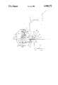
- the protective conductor connector of the present invention as shown in the drawing is adapted for use in connection with the housing 1 of an electrical terminal which is adapted for mounting on a rail leg portion 2 of a support rail 3.
- a clamping screw 4 is arranged within a protective conductor clip 5 of the terminal housing. As shown in the drawing, the clamping screw is spaced from the end of the rail leg portion 2 so that the screw is accessible. This arrangement is necessary in the case of multi-tiered terminals. Otherwise, the clamping screw of an upper tier would be superimposed on the screws and connectors of the lower tiers.
- the connector includes a hollow terminal carrier 7 which contains a vertical tapped hole 6 which receives the clamping screw.
- the terminal carrier 7 extends laterally from the screw 4 to the support rail 3.
- the carrier is designed to lock the terminal on the rail.
- the carrier includes a first hook or clip portion 8 which extends beneath the support rail leg portion 2 and a second clip portion 9 which extends above and beyond the leg portion 2 for engaging the rail 3.
- the first and second clip portions 8, 9 define a jaw, the opening of which has a width designed for mounting the assigned electrical terminal on the rail.
- the configuration of the jaw opening conforms with the configuration of the rail and leg portion on which the terminal is to be mounted.
- the other side of the support rail 3 also includes a leg portion on which the assigned electric terminal is fixed.
- the invention is characterized by a slider 10 arranged within the terminal carrier 7.
- the slider extends laterally from beneath the clamping screw 4 to over the support rail leg portion 2.
- the slider includes a clamping surface 11 arranged opposite the bottom of the clamping screw.
- the surface 11 is spaced from the screw 4 to receive the conductor 12 to be connected.
- the clamping surface engages the conductor.
- the slider has a toothed clamping zone 13 that engages the upper surface of the rail leg portion 2.
- the slider 10 also includes an inner upwardly directed extension 14 and an outer downwardly directed extension 15 which define guide surfaces 16, 17, respectively.
- the guide surfaces are arranged in parallel planes.
- the terminal carrier 7 includes projections such as a rounded strap 18 and a rounded end piece 19 extending from diagonally opposite surfaces thereof.
- the guide surfaces 16, 17 of the slider are guided by the projections 18, 19 of the terminal carrier 7 during movement of the slider to its connecting position.
- the clamping screw 4 With the conductor 12 arranged between the clamping screw 4 and the clamping surface 11 of the slider 10, the clamping screw 4 is tightened to force the conductor 12 and the slider 10 downwardly, whereby the conductor 12 is clamped between the screw and the slider clamping surface. Because of the inclined guide surfaces on the slider, the slider is also displaced laterally as it is forced downwardly by the screw since the guide surfaces 16, 17 slide down the projections on the terminal carrier. The lateral movement of the slider causes the teeth of the slider clamping zone 13 to scratch the layer of corrosion preventing material from the support rail leg portion. This insures that a reliable connection is provided between the conductor and the rail via the slider, regardless of the diameter of the conductor.
Landscapes
- Engineering & Computer Science (AREA)
- Power Engineering (AREA)
- Connections Arranged To Contact A Plurality Of Conductors (AREA)
- Connections By Means Of Piercing Elements, Nuts, Or Screws (AREA)
- Electric Cable Installation (AREA)
- Linear Motors (AREA)
Applications Claiming Priority (2)
| Application Number | Priority Date | Filing Date | Title |
|---|---|---|---|
| EP89105408A EP0389651B1 (de) | 1989-03-28 | 1989-03-28 | Schutzleiteranschluss zum Anschliessen an eine Tragschiene |
| EP89105408.2 | 1989-03-28 |
Publications (1)
| Publication Number | Publication Date |
|---|---|
| US4968272A true US4968272A (en) | 1990-11-06 |
Family
ID=8201140
Family Applications (1)
| Application Number | Title | Priority Date | Filing Date |
|---|---|---|---|
| US07/475,876 Expired - Lifetime US4968272A (en) | 1989-03-28 | 1990-02-06 | Protective conductor connector |
Country Status (7)
| Country | Link |
|---|---|
| US (1) | US4968272A (de) |
| EP (1) | EP0389651B1 (de) |
| JP (1) | JPH0626158B2 (de) |
| AT (1) | ATE109930T1 (de) |
| CA (1) | CA2013118A1 (de) |
| DE (1) | DE58908191D1 (de) |
| ES (1) | ES2056991T3 (de) |
Cited By (2)
| Publication number | Priority date | Publication date | Assignee | Title |
|---|---|---|---|---|
| US5704805A (en) * | 1995-03-31 | 1998-01-06 | The Whitaker Corporation | Connector for connection to a rail |
| US20080264663A1 (en) * | 2007-04-27 | 2008-10-30 | Meyer Gregory S | Apparatus and method for enhancing conductivity |
Families Citing this family (2)
| Publication number | Priority date | Publication date | Assignee | Title |
|---|---|---|---|---|
| DE102015218764A1 (de) * | 2014-12-30 | 2016-06-30 | Bender Gmbh & Co. Kg | Verfahren und Vorrichtung zur Überwachung einer Schutzleiterverbindung |
| CN112563771B (zh) * | 2020-12-04 | 2022-10-04 | 苏州市博发电气设备有限公司 | 一种高稳定性镀铜接地组合结构 |
Citations (6)
| Publication number | Priority date | Publication date | Assignee | Title |
|---|---|---|---|---|
| DE2461331A1 (de) * | 1974-12-24 | 1976-07-08 | Wieland Elektrische Industrie | Schutzleiter-reihen-anschlussklemme |
| DE2845532A1 (de) * | 1978-10-19 | 1980-04-24 | Weidmueller Kg C | Reihenklemme mit schutzleiteranschluss |
| DE2941932A1 (de) * | 1979-10-17 | 1981-05-07 | Georg Schlegel, 7941 Dürmentingen | Reihenklemme mit schutzleiteranschluss |
| DE3126535A1 (de) * | 1981-07-04 | 1983-02-10 | Phönix Elektrizitätsgesellschaft H. Knümann GmbH & Co KG, 4933 Blomberg | Elektrische reihenklemme |
| DE3339365A1 (de) * | 1983-10-29 | 1985-05-09 | F. Wieland, Elektrische Industrie GmbH, 8600 Bamberg | Schutzleiter-verbindungsklemme fuer hutfoermige tragschienen |
| DE3526494A1 (de) * | 1985-07-24 | 1987-01-29 | Siemens Ag | Schutzleiteranschlussklemme |
-
1989
- 1989-03-28 AT AT89105408T patent/ATE109930T1/de not_active IP Right Cessation
- 1989-03-28 DE DE58908191T patent/DE58908191D1/de not_active Expired - Lifetime
- 1989-03-28 ES ES89105408T patent/ES2056991T3/es not_active Expired - Lifetime
- 1989-03-28 EP EP89105408A patent/EP0389651B1/de not_active Expired - Lifetime
-
1990
- 1990-02-06 US US07/475,876 patent/US4968272A/en not_active Expired - Lifetime
- 1990-03-26 JP JP2073596A patent/JPH0626158B2/ja not_active Expired - Lifetime
- 1990-03-27 CA CA002013118A patent/CA2013118A1/en not_active Abandoned
Patent Citations (6)
| Publication number | Priority date | Publication date | Assignee | Title |
|---|---|---|---|---|
| DE2461331A1 (de) * | 1974-12-24 | 1976-07-08 | Wieland Elektrische Industrie | Schutzleiter-reihen-anschlussklemme |
| DE2845532A1 (de) * | 1978-10-19 | 1980-04-24 | Weidmueller Kg C | Reihenklemme mit schutzleiteranschluss |
| DE2941932A1 (de) * | 1979-10-17 | 1981-05-07 | Georg Schlegel, 7941 Dürmentingen | Reihenklemme mit schutzleiteranschluss |
| DE3126535A1 (de) * | 1981-07-04 | 1983-02-10 | Phönix Elektrizitätsgesellschaft H. Knümann GmbH & Co KG, 4933 Blomberg | Elektrische reihenklemme |
| DE3339365A1 (de) * | 1983-10-29 | 1985-05-09 | F. Wieland, Elektrische Industrie GmbH, 8600 Bamberg | Schutzleiter-verbindungsklemme fuer hutfoermige tragschienen |
| DE3526494A1 (de) * | 1985-07-24 | 1987-01-29 | Siemens Ag | Schutzleiteranschlussklemme |
Cited By (3)
| Publication number | Priority date | Publication date | Assignee | Title |
|---|---|---|---|---|
| US5704805A (en) * | 1995-03-31 | 1998-01-06 | The Whitaker Corporation | Connector for connection to a rail |
| US20080264663A1 (en) * | 2007-04-27 | 2008-10-30 | Meyer Gregory S | Apparatus and method for enhancing conductivity |
| US7697305B2 (en) * | 2007-04-27 | 2010-04-13 | Hewlett-Packard Development Company, L.P. | Apparatus and method for enhancing conductivity |
Also Published As
| Publication number | Publication date |
|---|---|
| JPH0626158B2 (ja) | 1994-04-06 |
| EP0389651B1 (de) | 1994-08-10 |
| DE58908191D1 (de) | 1994-09-15 |
| EP0389651A1 (de) | 1990-10-03 |
| JPH02288078A (ja) | 1990-11-28 |
| CA2013118A1 (en) | 1990-09-28 |
| ES2056991T3 (es) | 1994-10-16 |
| ATE109930T1 (de) | 1994-08-15 |
Similar Documents
| Publication | Publication Date | Title |
|---|---|---|
| CA1082785A (en) | Electrical termninal plug connector | |
| US6270383B1 (en) | Resilient terminal including conductor centering means | |
| US20020016098A1 (en) | Electrical wiring device with multiple types of wire terminations | |
| US4929198A (en) | Conductor connection assembly | |
| US6350162B1 (en) | Resilient electrical contact for large conductors | |
| US5236377A (en) | Electrical wire connector | |
| US4270835A (en) | Rail-mounted electrical terminals | |
| US5439384A (en) | Socket having an auxiliary electrical component mounted thereon | |
| US4968272A (en) | Protective conductor connector | |
| US5174767A (en) | Conductor connector assembly | |
| US3657683A (en) | Combination lead wire terminal | |
| US4077696A (en) | Electrical terminal | |
| US4365861A (en) | Wire terminal | |
| JPH0426186B2 (de) | ||
| CA2349284C (en) | Electrical connector contact bridge with wire clamps | |
| US5429532A (en) | Cable shield ground clamp | |
| US5679032A (en) | Strain relief device for clamp assembly | |
| EP0263325A3 (en) | Electrical connection or terminal clamps | |
| US6183303B1 (en) | Shielded cable end-processing construction | |
| US2231916A (en) | Solderless connector | |
| CA1109132A (en) | Terminals for receiving both quick connect terminals and stripped wires | |
| US2997688A (en) | Connector | |
| US2231868A (en) | Solderless connector | |
| GB2185159A (en) | Cable connectors | |
| WO2005008843A2 (en) | Electric equipment module structure |
Legal Events
| Date | Code | Title | Description |
|---|---|---|---|
| AS | Assignment |
Owner name: C.A. WEIDMULLER GMBH & CO., A CORP. OF F.R. GERMAN Free format text: ASSIGNMENT OF ASSIGNORS INTEREST.;ASSIGNORS:HANNING, WALTER;PAMPEL, JURGEN;STEINKUHLE, FERDINAND;AND OTHERS;REEL/FRAME:005229/0125 Effective date: 19900130 |
|
| STCF | Information on status: patent grant |
Free format text: PATENTED CASE |
|
| FPAY | Fee payment |
Year of fee payment: 4 |
|
| FEPP | Fee payment procedure |
Free format text: PAYOR NUMBER ASSIGNED (ORIGINAL EVENT CODE: ASPN); ENTITY STATUS OF PATENT OWNER: LARGE ENTITY |
|
| FPAY | Fee payment |
Year of fee payment: 8 |
|
| FPAY | Fee payment |
Year of fee payment: 12 |